
Specifications


10 DE5458
H. With the cabinet free of the hangers you can pull the
bottom of the cabinet away and free it from the dual
prong catch at the bottom of the bracket.
Figure 32. Releasing the Catch
5.2 Replacing the Backup Battery
CAUTION! If you replace rechargeable cells
with alkaline (dry) cells, be sure to install the
battery-type jumper in the “DRY” position.
Failure to do so will result in rapid cell
destruction and leakage (acid leakage may
cause further damage).
Figure 33. Jumper in Dry Battery Position
Replacement and first-time insertion of cells are similar
(see Para. 3.2). The only difference is the necessity to
remove the old cells and to inspect the battery holder
contacts and springs for signs of corrosion.
If corrosion is found in the battery holder, clean it first with
a piece of cloth dampened with hot water and then file the
contacts clean until they shine. In extreme cases, the
entire battery holder should be replaced.
With fresh battery cells, correct insertion and tightened
battery compartment lid, the TROUBLE indicator should
extinguish. However, the “MEMORY” message will now
blink in the display (caused by the “tamper” alarm you
triggered when opening the battery compartment lid).
Clear it by arming the system and immediately disarming.
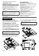
5.3 Fuse Replacement
The PowerArt™ has two fuses which can burn out:
" Battery Fuse - 1A, time delay type, UL recognized
(exists in U.S. variants only).
" Siren Fuse - 0.5 A, time delay type, UL recognized (in
the U.S.A.) or 0.5 A, time delay type, per IEC127-3 (in
Europe).
If any one of the fuses burns out (in U.S.A. variants) or the
siren fuse burns out (in other variants), the trouble
indicator lights and TRBL is displayed (together with
READY or NOT READY - as the case may be). Clicking
the <SHOW /OK> button will display a FUSE TROUBLE
message.
The fuse(s) is (are) accessible through the rectangular
opening at the rear of the cabinet (see figure 34). To
replace a fuse, the cabinet should be temporarily
dismounted (as described in Para. 5.1 above).
Extract the suspected fuse and check it visually. In most
cases, a defective fuse can be identified by the broken
conductor within the glass cylinder. If in doubt, test the
continuity of the fuse with an ohmmeter.
Replace a defective fuse with a new one of the same
ratings. The relevant trouble indications will immediately
disappear.
Figure 34. Fuse Locations