d me tion d me tion d me tion d sed User Guide PowerLink2 Advanced Internet-based Home Control Solution
Table of Contents Table of Contents Chapter 1 Getting Started ................................................................................................... 4 Introduction ................................................................................................................ 4 Specifications ............................................................................................................. 5 Software .................................................................................
Table of Contents Viewing Device Information ................................................................................... 28 Filter by Device Status......................................................................................... 29 Filter by Device Type .......................................................................................... 30 Filter by Location ................................................................................................ 31 Editing Device Setup ........
Table of Contents Filtering / Searching Home Devices list .............................................................. 54 Controlling Your Cameras ................................................................................... 55 Reading the Event Log (XHTML only) .............................................................. 58 Glossary ................................................................................................................... 59 Alarm .........................................
Getting Started Chapter 1 Getting Started Introduction The Visonic PowerLink2 enables you to view and control the Visonic PowerMax Security System over the Internet. The PowerLink2 is compatible with the PowerMaxPro control panel version 5.2.6C and above, PowerMaxComplete control panel version 2.0.6C and above, and with all control panels that support Partition 2. It provides the following advanced features: • Event notifications to Email and mobile phones.
Getting Started Specifications Software Security System • Commands o Arm Away o Arm Home o Disarm • Status o PowerMax LCD Status o Arming Mode o Zone Information: Zone Number, Zone Type, Zone Status, Location. o Accessories Status: Keypads, Keyfobs, Sirens, Commanders. o Alarm Indication: Burglar, Fire, Flood, Gas, Emergency, Panic, Tamper. o Trouble Indication: Inactivity, Low Battery, Tamper Open, Line Failure, AC Failure, RF Jamming.
Getting Started • The Visonic PowerLink2 supports a variety of cameras. For an updated list of cameras go to the www.visonic.com web site and from the PowerLink2 page, click on the "Supported Camera Range" link.
Getting Started OS • Embedded Linux Memory • 32MB RAM • 256MB Flash PowerMax Connection • RS-232 Power Supply • Powered From PowerMax via RS-232 connection Size • Internal PowerLink2: 73X61.5X16mm (2-7/8 x 2-7/16 x 5/8 in.) Weight • Internal PowerLink2: 50g (1.8 oz.
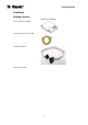
Getting Started Installation Package Contents Internal PowerLink2 1 x Visonic PowerLink2 1 x 2m (6.
Getting Started System Requirements • PowerMax Security System. • High-Speed Internet connection (Cable or DSL) enabled via a Home Router (Ethernet Based). • One free Ethernet port on the home router for the PowerLink2 connection. • One free Ethernet port on the home router for IP based camera enrollment (will be freed if camera is WiFi). • One free Ethernet port on the home router for every added Ethernet camera. • One of the supported browsers: o Internet Explorer version 6.
Installing the Visonic PowerLink2 Chapter 2 Installing the Visonic PowerLink2 Perform the following instructions for the Visonic PowerLink2 hardware installation: Note PowerLink2 operation is not backed up by the control panel's battery and it is shut down during AC failure. Hardware Installation Step 1. Open the control panel: PowerMaxPro PowerMaxComplete 2 1 Release screws 1 Release screws Step 2.
Installing the Visonic PowerLink2 Step 3 PowerMaxPro: 1. Connect the flat cable from the front panel to the PowerLink2. 2. Connect the Cat-5 cable from the PowerLink2 to the home router: Flat cable Cat-5 cable to home router PowerMaxComplete: 1. Connect the flat cable from the front panel to the PowerLink2. 2.
Installing the Visonic PowerLink2 Step 4. Close the panel and secure with 2 screws: Software Installation The Visonic PowerLink2 software installation procedure involves the following stages: · Control Panel Configuration · Router Configuration · Visonic PowerLink2 Configuration Control Panel Configuration The PowerLink2 is integrated with the PowerMax control panel. This facilitates in the setup of the required menus that are familiar to the installer.
Installing the Visonic PowerLink2 Programming for Configuring Events Reporting to Central Stations Follow the instructions below to select the type of events to be reported and to determine the method used for reporting events. 1. From the PowerMax control panel, enter "INSTALLER MODE" menu using the Installer Code. 2. Enter the "5.DEFINE COMM." menu. 3. Enter the "3:C.S.REPORTING" sub-menu. 4.
Installing the Visonic PowerLink2 IP Address Default Gateway 5. Copy the Default Gateway IP Address as the Home Router IP Address Value in the Visonic PowerLink2 Installation Form (See Appendix B). 6. Copy the first three blocks of the IP Address to the Visonic PowerLink2 IP Address Value in the Visonic PowerLink2 Installation Form (the last block of the IP Address is 200 if DHCP is used, see Appendix B). Example: The Default Gateway value is 192.168.0.1: The Home Router IP Address is 192.168.0.1.
Installing the Visonic PowerLink2 5. If requested, set the Port Forwarding rule name to PowerLink2. 6. Save the information. 7. If requested, restart the router and wait for the router to restart Step 4: Wi-Fi (Wireless Network) Configuration Perform this step if you intend to connect wireless cameras to the Visonic PowerLink2. 1. In your Router Configuration window, locate the Wireless Network configuration screen. 2. Set a value for the SSID.
Installing the Visonic PowerLink2 4. Choose your wireless encryption method 5. In the Encryption Key field type the Key String according to the Visonic PowerLink2 Installation Form (Appendix B). 6. Click button to apply the changes you've made. Connection Setup Parameters 7. Click Apply.
Logging Into The Visonic PowerLink2 Chapter 3 Logging Into The Visonic PowerLink2 You log in to the Visonic PowerLink2 through the Internet Browser. After you log in the Quick View window is displayed with an overall view of the security system. Loading time of the Quick View screen may vary due to the heavy amount of data presented. First time loading is expected to take longer than future loading times. To login to your Visonic PowerLink2 1. Open your Internet Browser. 2.
Logging Into The Visonic PowerLink2 4. Wait for the Login page to load. 5. In Visonic PowerLink2's Login screen type the Username and Password. Default Username and Password values (if not changed by owner or installer): Username: Admin Password: Admin123 Note that Username and Password are case-sensitive. 6. Click Login >>. If you are unable to login, call your Visonic PowerLink2 service provider or Installer for assistance. Once you have logged in, the Quick View screen appears.
Visonic PowerLink2 Window Chapter 4 Visonic PowerLink2 Window The Visonic PowerLink2 window displays the different views that enable managing the PowerMax Security System, Home automation devices and Cameras via the Internet: Quick View: Displays an overall view of the system status including video camera images. Security View: Gives a detailed overview of the security system including the current mode and status of the security system, detectors and accessories.
Visonic PowerLink2 Window Quick View When you log into the Visonic PowerLink2, the application opens in Quick View. The Quick View screen displays an overall view of the current status of the house subsystems controlled by the PowerMax Security System in three Information panes: 1 2 3 1 – Home Devices Pane 2 – Cameras Pane 3 – Security Pane In the following sections each Information pane of the Quick View screen is described in detail.
Visonic PowerLink2 Window Device Location Device Name The Connected Devices list includes information for all the home automation devices currently enrolled to the PowerMax: • • • Device name or Type – can be defined in the Home Devices screen accessed from the SETUP page. Device location, as defined in the PowerMax Security Control Panel. Available actions for a home automation device. These vary according to the device type. For example: a lamp can be dimmed and brightened.
Visonic PowerLink2 Window Camera currently being viewed Cameras available for viewing To view a camera: Click the camera name from the list of available cameras. The view will change to the selected camera and the name of the camera will be displayed at the top. To jump to the Cameras page: Click the icon at the top right of the pane. Security System Pane This pane displays the system status as seen on the LCD screen of the PowerMax Security System and enables changing the arming mode.
Managing Alerts and Alarms Chapter 5 Managing Alerts and Alarms The PowerMax Security System distinguishes between two major event types: Alarms and Alerts. Alarms are events that indicate that the security system is alarmed due to a burglar intrusion, a panic situation, an emergency situation or any other situation that is declared as an alarm situation. All trouble events or events that do not put the security system into Alarm mode are considered Alerts and should be treated as soon as possible.
Managing Alerts and Alarms Clicking on the alert indicator will open the alert popup. The alert popup displays the alerts details. Some alert messages such as Camera Enrollment messages can be dismissed and removed from the list. This can be done by clicking the dismiss link in the specific message. The Visonic PowerLink2 alert popup displays Alert indications as long as alerts exist in the security system.
Managing Alerts and Alarms QUICKACCESS ACTIONS ALARM DETAILS The Quick-access buttons enable you to do the following: • Mute the security system siren. • Turn all lights off or on. • View video cameras. • Disarm the Security system. Viewing Cameras during an Alarm During an alarm you can view video recorded by the cameras from the pre-alarm time (if pre-alarm time is configured) onward. You can also choose to view live video from the cameras. To view video cameras: 1.
Managing Alerts and Alarms 2. You can now do any of the following: • Click to display currently viewed video. Note You can then click to return to recorded video. • Click to open the Save As window and save the image as a graphic file on your computer. • Use the controls frame to Play, Pause and move the recording frame by Note For a detailed description of Cameras view see Managing Video Cameras on page 34. Closing the Alarm Mode Screen You can close the Alarm mode screen.
Managing Alerts and Alarms ALARM INDICATOR Note Click the Alarm Indicator to re-display the Alarm mode screen.
Managing Home Devices Chapter 6 Managing Home Devices The Visonic PowerLink2 enables PowerMax users that have an X10 transmitter module connected to the PowerMax control panel and X10 enabled appliances around the house to control these home devices over the Internet.
Managing Home Devices 2. You can now do one of the following: • To deactivate an active device: Click the icon of the required device. • To activate an inactive device: Click the icon of the required device. Filter by Device Status The By Device Status tab displays two lists: • Active Devices List: Includes all home automation devices currently turned ON. This list appears on the left side of the Work Area. • Inactive Devices List: Includes all home automation devices currently turned OFF.
Managing Home Devices Filter by Device Type The By Device Type tab lists all home automation devices of a selected type. Device Type Icons To display devices according to device type: 1. Switch to Home Devices view and click the By Device Type tab. 2. Click the Device Type icon of the type you require. All devices of this type are listed with the following information: • Device location • Device name or description. • Functionality actions according to device type.
Managing Home Devices Filter by Location The By Location tab lists all home automation devices by their location as defined in the PowerMax security control Panel. Device Location Icons To filter devices according to location: 1. Switch to Home Devices view and click the By Location tab. 2. Click the device location icon of the location you require. Note To scroll through the location list use the icons.
Managing Home Devices 2. Click the Home Devices tab. 3. In the Home Devices screen you can: • Type a new name in the DEVICE NAME field. • Click the arrow next to the TYPE field and in the window that appears click a new device type. 4. Click Apply. Searching for a Specific Device by Name A search engine enables a direct search of a specific home device by the device name. To search for a specific device in the Devices View screen: 1. Switch to Home Devices view and click the Search tab. 2.
Managing Home Devices Skip this step if you do not have any Home Automation devices enrolled into the system. 1. In the left frame of the Visonic PowerLink2 window click SETUP. 2. Click the HOME DEVICES tab. 3. In the Set Device Name And Type screen you can: Type a new name in the DEVICE NAME field. - or Click the arrow type. 4. next to the TYPE field and in the window click a device Click Apply to save your changes.
Managing Video Cameras Chapter 7 Managing Video Cameras The Visonic PowerLink2 supports up to 12 cameras. Cameras can be Wired (RJ-45 connector, Ethernet) or Wireless (Wi-Fi). Users who purchase the Visonic PowerLink2 along with cameras can view the camera images on-line over the Internet. For each connected camera, the Visonic PowerLink2 stores 5 frames of pre-alarm and 10 frames of post-alarm images.
Managing Video Cameras 5. Locate the ADD CAMERA area. 6. In the Location list click 7. You can disable web viewing of the camera by choosing at which arming mode the camera will be turned off. Clicking an arming mode icon will apply a small X to it, meaning that at this arming mode the camera will be off. 8. Click and select a location from the list.
Managing Video Cameras Click to open the alerts popup Clicking on dismiss will dismiss the message and it will disappear from the popup. When enrollment finishes successfully the camera will be added to the EDIT CAMERAS area of the Camera Configuration page. If the enrolled camera is a Wi-Fi camera, you may disconnect the Ethernet cable at this stage. To remove a camera: 1. In the Edit Cameras area locate the camera you want to remove and click the Remove icon. The camera is removed from the list.
Managing Video Cameras Current View Available Cameras Camera Controls The current view from each of the cameras enrolled in the system is displayed with the current image time and date. To view a camera click the desired camera from the Available Cameras pane and it will open at the Current view pane. Important A camera displaying No Data means that the PowerLink2 cannot retrieve the images from the camera. This might be a short network hiccup or a communication problem.
Managing Video Cameras Camera Configuration You can enroll new cameras to the PowerLink2, remove enrolled cameras and change the configuration of the cameras enrolled in the system. You can change the location, the orientation (flip & mirror) and on which arming modes the camera would not be accessible from the web interface. Add Camera Edit Cameras To edit the video camera configuration of the system: 1. In the side menu of the Visonic PowerLink2 window click . 2. Click the Cameras tab.
Managing Video Cameras • Click the icon to block viewing this camera from the web interface when the alarm system is in AWAY arming mode (Alarm images will still be recorded). The icon will change to indicating that this camera is blocked when alarm system is in AWAY arming mode. • Click the icon to block viewing this camera from the web interface when the alarm system is in HOME arming mode (Alarm images will still be recorded).
Managing the Security System Chapter 8 Managing the Security System The Security view Work Area displays a detailed overview of the security system including the current arming mode of the security system, the status of the security system, the list of detectors and their statuses and a list of other security system accessories. It enables you to remotely arm and disarm the security system in different arming modes.
Managing the Security System To change the arming mode: 1. Click the required arming mode in the list to set the Security System to the new mode. The new mode is marked Orange. Security Information Detectors The Security view displays a list of all the detectors enrolled in the system and their status. For each detector the list displays its Zone Name, Zone Number and Zone Type. Accessories The Security view displays information for system accessories.
Managing Users Chapter 9 Managing Users The Visonic PowerLink2 is pre-configured with a Master user called Admin. Only the Master user can access the Users and Setup views of the Visonic PowerLink2. Additional Users The Master user can add additional users to the Visonic PowerLink2. Users that are added appear in the ADDITIONAL USERS list. A Master user can also edit or add information to the Master user or to other users of the Visonic PowerLink2.
Managing Users To display the Users View: 1. In the side menu of the Visonic PowerLink2 window click 2. Click the Users tab. . The Users view is displayed. To change the Master user's name and password: 1. In Users view click the EDIT button under the PROFILE title. The following window appears. 2. Change the username from Admin to your own user name. 3. Change the password to your own password. 4. Repeat this step in the Confirm Password area. 5. Click APPLY.
Managing Users To change the Master user's name and password: 1. Click the EDIT button under the PROFILE title. 2. Change the username from Admin to your own user name. 3. Change the password to your own password. 4. Repeat this step in the Confirm Password area. 5. Click APPLY. Adding / Removing Users You can add up to seven additional users to the Visonic PowerLink2 (excluding the Master user). You can then remove any or all of these users. The Master user cannot be removed.
Managing Users The following window appears. 2. Edit the user profile according to your needs. 3. Click APPLY. The user profile is updated in Users view. Editing User Notifications User Notifications enables you to assign alarm/alert notifications to specific users. To assign User Notifications: 1. Click the USERS tab. The following window appears.
Managing Users 2. Edit the user notifications according to your needs. 3. Click APPLY.
Managing System Configuration Chapter 10 Managing System Configuration System Configuration Managing system configuration is done in Setup view. Setup view includes the following tabs: • Management: Connection and session related parameters. Factory reset and PowerLink2 ID. • Network: Network and Wi-Fi related parameters. • Users: Master user and Additional users management.
Managing System Configuration The Management tab includes the following: • PowerLink2 ID – Allows you to connect to the PowerLink2 with the ID instead of serial number. • Ports - Allows changing the network ports in which PowerLink2 operates. HTTP is the port used for accessing your PowerLink2 from the internal network. HTTPS is used for access from the internet. If PowerLink2 is connected to a router that supports UPNP, checking the Open using UPNP will open the ports on the router automatically.
Managing System Configuration • WiFi Parameters – The parameters of the WiFi network: • SSID – Network name. Note that some cameras will not accept an SSID that consists of nonalphanumeric characters. • WEP / WPA-TKIP/ None – The encryption methods available • Encryption Key – The key used for encryption.
Managing System Configuration Resetting to Factory Settings It is possible to reset the Visonic PowerLink2 to its Factory Settings. Resetting the Visonic PowerLink2 to its factory settings will remove all the enrolled cameras, defined users and defined names and types of Home Devices. Upon reset, the Master user is reset to the default username and password of the Visonic PowerLink2. To reset the Visonic PowerLink2 to it's factory settings: 1. In the Management TAB, click . 2.
Cellular Web Interface Chapter 11 Cellular Web Interface The PowerLink2 has two types of cellular web interfaces: WAP and XHTML. The XHTML interface is a graphic interface, similar to a regular web interface, and is intended for new generation cellular phones. The WAP interface is a textual interface that allows older types of cellular phones to control the PowerLink2. The system will automatically redirect your phone to the appropriate interface and will display the functions associated with the phone.
Cellular Web Interface Viewing the security status This allows you to view the status of your alarm system as it appears on the LCD screen. To view the status of your alarm system: 1. You can view the status of your alarm system from the main menu (XHTML). On the WAP cellular interface, select Security. The Security screen appears. Setting the security mode This allows you to arm or disarm the system using your cellular phone. To arm or disarm the system: 1.
Cellular Web Interface 4. To return to the main menu, click the button on your Visonic PowerLink2 or click the button on your cellular phone (WAP only). Controlling Home Devices Controlling Home Devices allows you to turn on and off the home appliances connected to the alarm system and to apply to them specific actions. To control a home device: 1. From the main menu, select Home Devices. The Home Devices screen appears.
Cellular Web Interface 2. Click on the desired action you want to apply to the device. The updated action will appear on the Home Devices screen. Device Action Updated 3. button on your Visonic To return to the main menu, click the PowerLink2 or click the button on your cellular phone. Filtering / Searching Home Devices list This provides a quick way to search for the appliance you want to control. Note The instructions below are intended for WAP cellular phones.
Cellular Web Interface 3. Click on the type of Search you want to apply. Select between Status, Location or Type. 4. Make your selection from the drop down menu and then click on Filter. Make your selection from the list. 5. The list is now filtered according to your selection. 6. To return to the main menu, click the button on your Visonic button on your cellular phone.
Cellular Web Interface Click on the camera name you want to Click on the zone name where the camera you want to view is view. located. Refresh Image Size Alarm Images Here you can set the view refresh rate. Mini View Additional Cameras The image size link allows you to change the size of the viewed image. Click on the Quick View to open the larger camera feed (additional controls are located here).
Cellular Web Interface Pan/Tilt Controls Alarm images Click on the image to return to the previous page. Use the arrows in the image to pan and tilt a camera Use the up / down / left / right links to pan and tilt (applicable only to cameras that support this feature). a camera that supports Use the orange icon to view alarm images of the last this feature (Visonic recorded alarm. CAM3200).
Cellular Web Interface Reading the Event Log (XHTML only) Events are stored in the event log. You can access this log and review the events, one by one. The date and time of occurrence are memorized for each event. When reading the event log, events are shown in chronological order as defined by the PowerMax – usually from the newest to the oldest. To review the event log: 1. Select PowerMax logs from the main menu. 2. Review the events in the event log.
Glossary Glossary Alarm An alarm situation is initiated when an alarm trigger is being sent from one of the detectors attached to the alarm system. Different detectors types can be: • PIR – Detect motion in the zone (room) where they are installed. • Door contact – Detects the opening of a door or a window. • Glass Break – Detects a glass breaking event. • Fire – Detects a fire situation. • Flood – Detects a flood situation • Gas – Detects a leak of gas.
Glossary these detectors are installed during the night. In this mode, the security system threats all the detectors that are assigned to perimeter zones as immediate alarm initiators and to all detectors assigned to interior zones as non-alarm initiators. • Disarm – The DISARM mode is usually used when the house is occupied during day hours.
Glossary Not all Home Router manufacturers use the term "Port Forwarding". Alternative terms you may find in your Home Router can be: "Port Redirection", "Virtual Servers" and "Applications and Gaming". Home Router A router is a device that connects two networks. The network within the house is considered a LAN (Local Area Network). To enable Internet access from a LAN, a connection to the WAN (Wide Area Network) has to be established using a router.
WARNING: Changes or modifications to this unit not expressly approved by the party responsible for compliance could void the user's authority to operate the equipment. NOTE: This equipment has been tested and found to comply with the limits for a Class B digital device, pursuant to part 15 of the FCC Rules. These limits are designed to provide reasonable protection against harmful interference in a residential installation.
Appendix A Troubleshooting Problem During Adding Cameras procedure, Camera view is lost after disconnecting RJ-45 connector. Diagnosis 1. WiFi parameters are incorrect. 2. WiFi coverage does not include the camera. The user cannot access the web interface of the PowerLink2 from within the home premises. 1. The PowerMax control panel is not connected to the electrical power socket. 2.
Appendix B PowerLink2 Installation Form Parameter Value Home Router IP Address ____ . ____ . ____ . ____ PowerLink2 IP Address ____ . ____ . ____ . 200 SSID Encryption method WEP / WPA-TKIP / None WEP Key String PowerLink2 Remote URL W.E.E.E. Product Recycling Declaration For information regarding the recycling of this product you must contact the company from which you orignially purchased it.
©Visonic LTD.