USER GUIDE PowerMaster-10 G2 Fully supervised wireless alarm control system www.visonic.
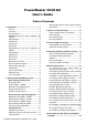
PowerMaster-10/30 G2 User's Guide Table of Contents 1. Introduction .................................................... 3 Preface ......................................................... 3 Overview ....................................................... 3 System Features ........................................... 3 PowerMaster-10 G2 Panel Indicator and Controls ........................................................ 4 LED Indicators .............................................. 4 Control Keys .........
Event notifications by Telephone ................ 39 Event notifications by SMS ......................... 40 Remote Control by Telephone .................... 40 Remote Control by SMS ............................. 41 8. Special Applications and Functions ........... 43 Looking after People Left at Home .............. 43 Acknowledging “low battery” condition in Keyfobs ....................................................... 43 9. Testing the System ...................................... 44 Periodic Test .....
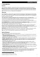
INTRODUCTION 1. Introduction Preface The PowerMaster-10/30 G2 is a highly advanced wireless alarm control system produced by Visonic Ltd. Note: Make sure that you have the name and telephone number of the monitoring station your system will report to. When calling the monitoring station to ask questions, you should have access to your "ACCOUNT NUMBER" used to identify your alarm system to the monitoring station. Obtain this information from your installer and write it.
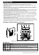
INTRODUCTION Numerical keys serve as function keys: When the system is disarmed, the numerical keys are used also to control various system functions. A simple icon on each key identifies the task of that key. Data retrieval: You can obtain status information, trouble information and review memorized alarm events visually (see Chapter 5). Event log: System events are memorized in an event log that stores the most recent events, each tagged with the time and date of the event.
INTRODUCTION Control Keys No. Indication Function 7 NEXT: Advance from item to item within a given menu. 8 BACK: Move one step back within a given menu. 9 OK: Review status messages one by one and also select a displayed option. Arming Keys No. Indication Function 12 AWAY: Arming when nobody is at home 10 HOME: Arming when people remain at home.
INTRODUCTION No. Indication Function 3 Arm (Red): Lights when the system is in the armed state. 4 Chime (Green): Chime zones will chime when disturbed (see Chapter 2). 5 Trouble (Orange): Lights when the system is in a state of trouble (see Chapter 5). Control Keys No. Indication Function 7 NEXT: Advance from item to item within a given menu. 8 BACK: Move one step back within a given menu. 9 OK: Review status messages one by one and also select a displayed option. Arming Keys No.
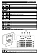
INTRODUCTION Built-in Alarm Sounder The PowerMaster panel has a high power siren built-in that sounds in case of alarm to deter intruders and to summon help. The maximum operating time of the siren is configured by the installer according to local regulations. Continuously ON when initiated by a burglar zone or a 24-hour zone, and when a user initiates a “panic alarm”. When initiated by a fire zone (smoke is detected) ON - ON - ON - pause - ON - ON - ON - pause - ........ and so on.
INTRODUCTION Screen Saver Mode For security reasons, it is sometimes required to hide the status indication (LCD and LED display) from a potential intruder. If the Screen Saver option is enabled by the installer, then if no key is pressed for more than 30 seconds, the display will read “POWERMASTER-10 / POWERMASTER-30” and the LEDs will stop indicating any status. Pressing any key will resume the normal status display. Pressing the Fire or Emergency keys will also initiate the Fire or Emergency alarm.
OPERATING THE POWERMASTER SYSTEM 2. Operating the PowerMaster System For more information regarding terms used in this chapter, refer to APPENDIX C. GLOSSARY. Note: This manual displays PowerMaster-10 G2 panel buttons only, even when instructions refer to both panels. When an instruction refers to PowerMaster-30 G2 only, the PowerMaster-30 G2 panel buttons are displayed. Basic Arming and Disarming Following are a set of procedures for performing basic arming and disarming of the alarm system.
OPERATING THE POWERMASTER SYSTEM Disarming under Duress If you are forcibly compelled to disarm the system, enter the duress code (2580 by default) or another code set by the installer. Disarming will take place normally but a silent alarm will be transmitted to the monitoring station. Partition Selection Process Access to any desired partition is achieved through the use of an individual code or proximity tag.
OPERATING THE POWERMASTER SYSTEM Note: When forced arming is carried out, the buzzer “protests” by emitting a continuous tone during the exit delay until the last 10 seconds of the delay. You can silence this signal by pressing the arming button again.
OPERATING THE POWERMASTER SYSTEM PRESS RESULTING DISPLAY PANIC ALARM simultaneously READY HH:MM To stop the alarm, press the button and then key in your valid user code.
SPEECH AND SOUND CONTROL 3. Speech and Sound Control1 Speech & Sound Cont. Push-buttons The sound and speech-related functions offered by the control panel are controlled with the keypad, as detailed in the following list. When partitioning is enabled: Sound and speech-related features only apply to the partition(s) where the control panel is present. An activity performed via the control panel from another partition will be displayed and the LED will light.
SPEECH AND SOUND CONTROL Once the last of the boxes disappears, RECORDING ENDED will be displayed. When you release the button, the display will revert to the normal status-displaying mode, but will also indicate that a message is waiting. For example: READY HH:MM (alternating) READY MSG To check your own message, listen to it within one minute from the end of recording (see the next section Message Playback). This way the MSG indication will not be erased.
ELECTRICAL APPLIANCE CONTROL 4. Electrical Appliance Control Control Options and Pushbuttons The system allows manual or automatic remote control of a device connected to the PGM output. The user defines the ON and OFF times via the Scheduler (see Chapter 6 - B.13 Programming the Scheduler). The installer determines which zone sensors will switch the remote controlled appliances on and off.
REVIEWING TROUBLES AND ALARM MEMORY 5. Reviewing Troubles and Alarm memory Alarm & Tamper Memory Indication The PowerMaster retains in its memory alarm and “tamper” events that occurred during the last arming period. Note: Alarm events are memorized only after the “abort period” (see Appendix C). This means that if you disarm the system immediately - before the abort period expires - there will be no memory indication A.
REVIEWING TROUBLES AND ALARM MEMORY PRESS RESULTING DISPLAY POWERMASTER-10 1 Z09 LOW BATTERY (alternating) Z09 CONTACT (alternating) KITCHEN PRESS RESULTING DISPLAY Z15 MISSING (alternating) Z15 MOTION SENS (alternating) LIVING ROOM COMM. FAILURE READY HH:MM IMPORTANT! If the trouble beeps bother you, disarm the system again (even though it is already disarmed). This will cancel the trouble beeps for 4 hours. C.
MENUS AND FUNCTIONS 6. Menus and Functions This chapter explains the user programming features of your PowerMaster system and allows you to tailor the PowerMaster system according to your specific needs. The chapter is divided into three sections, as follows: Part A – Guides you how to enter/exit the User Settings menu and how to select the desired setting options. Part B – Guides you to execute the selected settings. A.
MENUS AND FUNCTIONS C. User Settings Options Menu Click until the display reads the desired setting option and then press SET ZONE BYPASS REVIEW BYPASS . Use to set the Zone Bypass Scheme i.e. to bypass (exclude) faulty or unsecured ("disturbed") zones, or to clear a bypassed zone (unbypass). For further details and programming procedure see section B.1. 3 Use to quickly review the Bypass Scheme i.e. which zones are bypassed. For further details and reviewing procedure see section B.2.
MENUS AND FUNCTIONS (see above) until the display reads [ TO EXIT], or preferably, press once which brings you immediately to the exit screen [ TO EXIT]. or TO EXIT When the display reads [ TO EXIT], press READY 12:00 The system exits the [USER SETTINGS] menu and returns to the normal disarm state while showing the READY display. A.3 Buttons used for Navigation & Setting The keypad's buttons are used for various functions when programming.
MENUS AND FUNCTIONS Z01: P1 P2 P3 4 Living Room 2. or Z04: NOT READY Z04: P1 P2 P3 3. Kitchen 4. TO BYPASS 5. Z04: BYPASSED Click the or button until the display reads the zone you wish to bypass (or clear bypass), for example, "Z04" for Zone 04. After several seconds the LED on the respective device starts flashing indicating "it's me". 4 When the display reads the zone you wish to bypass press . The display now reads [ TO BYPASS].
MENUS AND FUNCTIONS B.3 Recalling the Zone Bypass Scheme Use this option to repeat (recall) the most recent Bypassed Scheme for use during the next arming session. 1. RECALL BYPASS Enter the [USER SETTINGS] menu, select the [RECALL BYPASS] 1 option and press . 2, 6 2. TO RECALL The display now reads [ TO RECALL]. 7 To recall the last used bypass scheme press 3. Bypass RECALLED ☺ Return to step 1 . A "Happy Tune" ☺ sounds.
MENUS AND FUNCTIONS erased and must be replaced with a secret code as soon as possible. User Codes 2-4 (PowerMaster-10 G2) / User Codes 2-22 and 33-48 (PowerMaster-30 G2) are assigned to family members, co-workers etc. They enable arming and disarming of the system or of selected partitions as defined by the Master User. They can access the "User Settings" menu only for "zone bypassing" provided this option is enabled in the Installer menu.
MENUS AND FUNCTIONS ☺ Return to step 3 with Partition 1 and 3 only, press to confirm. A "Happy Tune" ☺ sounds. The display confirms the Partition setting. 9 Additional Information (section B.4) 1 2 3 4 5 6 7 8 9 For detailed instructions on how to select the setting options – refer to section B.1 and section B.2. The display shows the 1st User Code (Master User) in the list of 8 User Codes (in PowerMaster-10 G2 system) / 48 User Codes (in PowerMaster-30 G2).
MENUS AND FUNCTIONS or T05:Tag (Prox) ☺ Return to step 2 To assign the tag to another user, for example, "User No. 5", key in [05] or alternatively click the or button until the display reads [T05:Tag (Prox)] and then press to confirm. The display reads [DEVICE ENROLLED] a "Happy Tune" ☺ sounds and the display will then change to [T01:Tag (Prox)]. 5 6 B. To Set Partitions Authorization The display will read [T05:PARTITIONS]. 9 6. T05:PARTITIONS 7.
MENUS AND FUNCTIONS 5 6 7 8 9 10 11 12 If Partition is enabled, continue to step 6 (applicable to PowerMaster-30 G2 only). You can now enroll another proximity tag. You can also select another option in the User Settings menu (see section B.1 and section B.2), or quit programming (see section B.3). If no proximity tag is enrolled in the system, the display reads [NO EXISTING DEV.]. To abort the procedure, press the button. This setting can be performed only after completing steps 1 - 5 of section B.5A.
MENUS AND FUNCTIONS ID No. 300-5786 or F05:keyfob ☺ Return to step 2 the first free number, and the keyfob's ID number; for example: [F01:Keyfob] alternating with [ID No. 300-5786]. To assign the keyfob to another user, for example, "User No. 5", key in [05] or alternatively click the or button until the display reads [F05:Keyfob] and then press to confirm.
MENUS AND FUNCTIONS Additional Information (section B.6) 1 2 3 4 5 6 7 8 9 For detailed instructions on how to select User Settings – refer to section B.1 and section B.2. The LED will extinguish after several seconds. In case of difficulties in communication with the control panel, the LED may blink for several seconds more while trying to establish communication. During this period of time the keyfob keys are disabled. The display shows the first enrolled Keyfob (Keyfob No.
MENUS AND FUNCTIONS TIME 08:55A ☺ Return to step 2 A "Happy Tune" ☺ sounds, the display reads the set time, returns to step 2 and then reads the selected time format. 6, 7 Additional Information (section B.7) 1 For detailed instructions on how to select User Settings – refer to section B.1 and section B.2. 2 a. The display shows the currently selected format (indicated by a symbol), for example, "24 Hrs". 3 4 5 6 7 b.
MENUS AND FUNCTIONS on the first digit. 4 5 6 7 You can move the cursor to the next or previous digit using the or button. For the year, enter the two last digits only. You can now select another option in the User Settings menu (see section B.1 and section B.2), or quit programming (see section B.3). This setting can be performed only after completing steps 1 – 3 of section B.8A. B.
MENUS AND FUNCTIONS 4 The display shows the current setting of the Auto-Arm Time, for example, "12:00 PM", with the cursor blinking on the first hour digit "1". For detailed explanation of how to set the time - refer to Section B.7 B. 5 The saved auto arm time is displayed without the cursor, for example, " 08:30 A". 6 You can now select another option in the User Settings menu (see section B.1 and section B.2), or quit programming (see section B.3). B.
MENUS AND FUNCTIONS B. To Program a Private Phone 6. REPORTED EVENTS or Click the or button until the display reads the desired Telephone No. you wish to program or edit, for example, "2nd private tel#", and press . 7. 2nd private tel# 8. 032759333 To program or edit the phone number, at the blinking cursor position enter the phone number, for example, “8032759333”, using the numerical keypad. 6, 7 When done, press to confirm.
MENUS AND FUNCTIONS E. To Program the Acknowledge Method 18. Voice<- ->private or Click the and press or button until the display reads [Tel. acknowledge] to confirm. 12 Tel. acknowledge 19. by single ack 20. or The display shows the currently selected option. Click the or button until the display reads the desired acknowledge method, for example, "by all ack". 11 by all ack 21. all ack ☺ Return to step 19 A "Happy Tune" ☺ sounds.
MENUS AND FUNCTIONS Additional Information (section B.11) 1 For detailed instructions on how to select User Settings – refer to section B.1 and section B.2. 2 This option allows you to program the events to be reported. To program telephone numbers, click the or button until the display reads the desired option. 3 The display shows the currently selected option (indicated by a symbol), for example, "disable report".
MENUS AND FUNCTIONS 12 If the control panel is PowerMaster-10 G2 or PowerMaster-30 G2 without Voice option, the display reads "Redial attempts". 13 You can now, select other options, end this session – (see section B.1 and section B.2), or quit programming (see section B.3). B.
MENUS AND FUNCTIONS B. To Set the Day 2 The 1st day of the scheduler is displayed. Sunday 3. Click the or button until the display reads the day you wish to schedule or "Daily", for example, "Tuesday". 2 or Tuesday 4. When the "day" to schedule appears on the display, press C. To Select the Activation No. 5. . 3 The 1st operation (PGM output activation) of the scheduler is displayed.
MENUS AND FUNCTIONS 5 6 7 The screen also displays the selected time format. The display shows the current start or stop time setting of the selected activation with the cursor blinking on the first hour digit. If no time is programmed, the time display will be blank (- -:- - - ). For detailed explanation of how to set the time - refer to Section B.7 B. To end this session and return to the previous "operation" menu, press the button.
MENUS AND FUNCTIONS Additional Information (section B.14) 1 For detailed instructions on how to select the Setting Options – refer to section B.1 and section B.2. 2 a. The display shows the currently selected setting (indicated by ), for example, "enable prompts". b. You can now enable (voice prompts) or disable (no voice prompts) the voice option using the or 3 4 5 button. The symbol now appears next to the newly selected option.
EVENT REPORTING & CONTROL BY TELEPHONE AND SMS 7. Event Reporting and Control by Telephone and SMS Event notifications by Telephone The PowerMaster can be programmed for selective notification of event messages to private telephone subscribers – See Chapter – 6, B.11 Programming Private Phone and SMS Reporting.
EVENT REPORTING & CONTROL BY TELEPHONE AND SMS Event notifications by SMS Note: This feature is not to be not to be enabled in UL Listed product. The PowerMaster system when equipped with a GSM unit can be programmed to send SMS event notification messages to 4 pre-selected telephone numbers - see Chapter – 6, B.11. The messages can be tagged with a "House ID" name, for example, "JOHN'S HOUSE", see Remote Control by SMS section, command no. 10.
EVENT REPORTING & CONTROL BY TELEPHONE AND SMS Command 8 9 10 11 12 13 14 15 16 17 Single Partition Keying Sequence/PowerMaster-10 G2 Review status of specific partition (Voice version only) 1, 2 Activating PGM output 1 Deactivating PGM output 1 Two-way voice communication 1 (see sub-par.
EVENT REPORTING & CONTROL BY TELEPHONE AND SMS PowerMaster system with GSM unit can respond to SMS commands from any cellular telephone (a detailed SMS message sending process is described in the cellular telephone user’s guide). The various SMS commands are detailed in the following table. In this table, “” means a 4-digit user code and simply means blank space (see Note).
SPECIAL APPLICATIONS AND FUNCTIONS 8. Special Applications and Functions Looking after People Left at Home In addition to acting as an alarm system, the PowerMaster can also be used to monitor the movement of people at home when the system is in the disarmed state (or even when armed “HOME” with perimeter protection only), and report lack of motion in interior zones if there is no detection of motion within predetermined time limits.
TESTING THE SYSTEM 9. Testing the System Periodic Test The components of your security system are designed to be maintenance-free as much as possible. Nevertheless, it is mandatory to test the system at least once a week and after an alarm event to verify that all system sirens, detectors, keyfobs, keypads and other peripherals function properly. Proceed as described in this section and if there is any problem, notify your installer at once.
TESTING THE SYSTEM Z01 24.5C Z01:Temp. Sensor The control panel reads the temperature of each zone. The display alternates between the temperature, the sensor number and the sensor location. 8 Repeatedly click the button to review the temperature of each zone (by Temperature Sensor). Guest room DEVICE TESTS END 9. or When the temperature of all zones has been reviewed, the display reads [DEVICE TESTS END].
MAINTENANCE 10. Maintenance Replacing the Backup Battery There is generally no need to replace the battery since the battery is rechargeable. If a CPU LOW BATTERY trouble message is received when the control panel is connected to AC power and this trouble state continues for more than a few hours, the battery may need to be replaced. An original Visonic battery must be used of which there are a number of types. For assistance in battery replacement, contact Technical Support.
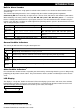
MAINTENANCE Reading the Event Log To read the event log, proceed as follows: READY 00:00 1. ENTER CODE: _ 2. When the PowerMaster display reads [ENTER CODE: _], enter the current master user code. CODE LIST OF EVENTS 3. Z13 alarm 09/02/10 3:37 P The "Happy Tune" will sound and the PowerMaster display will read [LIST OF EVENTS]. (see Important Note!) Click the button. The latest event will be shown. The event is displayed in two parts, for example, "Z13 alarm" then "09/02/10 3:37 P".
APPENDICES APPENDIX A. FUNCTIONS OF CONTROLLING DEVICES A1. KP-160 PG2 Arming and Disarming the System Optional Optional Step Operation 1 Select a PARTITION (if Partition is enabled) 2 Arm AWAY 3 4 User Actions Keyboard & Panel Response The selected key blinks.
APPENDICES A2. KP-140/141 PG2 Arming and Disarming the System Step 1 Basic Arming User Actions Select a PARTITION (Partition enabled) Keypad & Panel Response The selected button lights. or or The selected button starts blinking and prompts you to enter your "User Code" or present your Tag. See step 3. Arm AWAY Arm HOME 2 Disarm (OFF) The keypad's LED blinks red once to indicate transmission of the arming command to the control ( 2 sec.) panel.
APPENDICES A3. KF-234 PG2 Keyfob Functionality Step Functions User Actions Arm AWAY 1 When executing a command, the keyfob's LED blinks red once to indicate transmission of the command to the control panel. If the operation is successfully completed, the green LED lights momentarily and a "happy tune" is heard.
APPENDICES Arming/Disarming a Single Partition To arm/disarm a single partition, press the number: 1; 2; or 3. Then, press the button on the control panel and then press the Partition / or button. B3. The Show Function The show function is enabled during single/all partition(s) status and displays information that is relevant to the selected or all partitions. Show All Partitions In Ready mode press , the display will show information on all partitions. Press repeatedly to view memory / status content.
APPENDICES APPENDIX C. GLOSSARY This list of terms is arranged in alphabetical order. Abort Period: When an alarm is initiated, the internal built-in sounder is activated first for a limited period of time which is the abort period set by the installer. If you cause an alarm accidentally, you can disarm the system within the abort period before the real sirens start and before the alarm is reported to the remote responders.
APPENDICES still disturbed upon termination of the exit delay. Bypassed zones will not be protected throughout the arming period. Even if restored to normal (closed), bypassed zones will remain unprotected until the system is disarmed. Permission to “force arm” is given or denied by the installer while programming the system. HOME: This type of arming is used when people are present within the protected site. A classic example is night-time at home, when the family is about to retire to bed.
APPENDICES User Codes: The PowerMaster is designed to obey your commands, provided that they are preceded by a valid security access code. Unauthorized people do not know this code, so any attempt on their part to disarm or defeat the system is bound to fail. Some operations, however, can be carried out without a user code as they do not degrade the security level of the alarm system. Zone: A zone is an area within the protected site under supervision of a specific detector.
APPENDICES APPENDIX E. SPECIFICATIONS E1. Functional Zones Number Hard-wired Zone Requirements Maximum Loop Current Maximum Loop Voltage Loop Shorted Loop Normal Loop Tampered Loop Alarm Loop Open Installer and User Codes Control Facilities Display Arming Modes Alarm Types Siren Signals Siren (bell) Timeout Internal Sounder Output Supervision Special Functions Data Retrieval PowerMaster-10 G2 30 wireless zones (including 1 hard-wired input). 2.2 kE.O.L. resistance (max.
APPENDICES Real Time Clock (RTC) Battery Test PowerMaster-10 G2 The control panel keeps and displays time and date. This feature is also used for the log file by providing the date and time of each event Once every 10 seconds PowerMaster-30 G2 The control panel keeps and displays time and date.
APPENDICES PowerMaster-10 G2 Time to Charge Optional Backup Battery Pack Time to Charge (optional backup battery pack) Wired Detectors Total (Sum) Current Site External Siren Current (EXT) Site Internal Siren Current (INT) 80 % ( 13 Hrs) See "Backup Battery Options" above PowerMaster-30 G2 by GP or equivalent. 4. 9.6V 2200 mAh, rechargeable NiMH battery pack (special order) or equivalent. 5. 7.2V 1800 mAh, rechargeable NiMH battery pack, p/n GP180AAH6BMX, manufactured by GP only.
APPENDICES Storage Temp. Range Humidity Size Weight Color -4°F to 140°F (-20°C to 60°C) -4°F to 140°F (-20°C to 60°C) 93% relative humidity, @ 30°C (86°F) 196 x 180 x 55 mm (7-5/8 x 7 x 2 in.) 658g (23 Oz) (with battery) White 93% relative humidity, @ 30°C (86°F) 266 x 201 x 63 mm (10-7/16 x 7-7/8 x 2-1/2 in.) 1.44Kg (3.2 pounds) (with battery) White E6.
APPENDICES According to EN 50131-1:2006 and A1:2009, this equipment can be applied in installed systems up to and including Security Grade 2. EN 50131-1 Environmental Class Class II This device complies with FCC Rules Part 15 and with Industry Canada licence-exempt RSS standard(s). Operation is subject to two conditions: (1) This device may not cause harmful interference, and (2) this device must accept any interference that may be received or that may cause undesired operation.
W.E.E.E. Product Recycling Declaration For information regarding the recycling of this product you must contact the company from which you orignially purchased it. If you are discarding this product and not returning it for repair then you must ensure that it is returned as identified by your supplier. This product is not to be thrown away with everyday waste. Directive 2002/96/EC Waste Electrical and Electronic Equipment. EMAIL: INTERNET: VISONIC LTD. 2013 info@visonic.com www.visonic.
USER GUIDE PowerMaster-30 G2 Fully supervised wireless alarm control system www.visonic.com © 2013 Visonic Ltd. All rights reserved.