©Visonic LTD.
PowerMaxComplete User Guide Table of Contents Compatibility of this Manual ..............................2 Quick Guide To Primary Alarm Control Operations ...........................................................2 Contact list form..................................................2 Luminous Indicator Signals ...............................2 Siren Signals .......................................................3 Useful Hints For PowerMaxComplete Users .3 1. Introduction .....................................
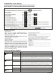
Compatibility of this Manual This manual should be used with PowerMaxComplete v2.0.00 and above. Quick Guide To Primary Alarm Control Operations QUICK REFERENCE TO PRIMARY ALARM CONTROL OPERATIONS Active Partition Selection (when partition is enabled) Arming AWAY-INSTANT......................... Arming HOME ......................................... Arming HOME-INSTANT ........................ Arming AWAY-LATCHKEY ....................
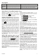
Siren Signals Alarm Type Graphic Representation of Signal Burglar / 24 ––––––––––––––––––––––––––––––– hour/ Panic – – – – – – – – – – – – ................. Fire –– (both external and internal sirens) Test* * Supplementary use only. Verbal Description of Signal ON continuously ON - ON - ON - pause - ON - ON - ON - pause .....
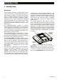
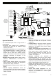
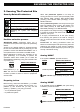
INTRODUCTION 1. Introduction Overview The PowerMaxComplete is a wireless alarm control system that provides protection against burglary, fire and tampering. In addition, it can be used to control a light or an electrical appliance within your household and/or to monitor the activity of disabled or elderly people left at home.
INTRODUCTION TEL SMS EMERGENCY PENDANT TRANSMITTERS DOOR OR WINDOW OPEN/CLOSE DETECTOR GSM TELEPHONE GPRS INTERNET EXCHANGE LOCAL COMPUTER (OPTION) WIRELESS SIRENS INTERNET ROUTER USER COMPUTER SITE INTERNAL SIREN OR STROBE UNIVERSAL PERIMETER PROTECTION DETECTOR WIRELESS DETECTORS (UP TO 28 UNITS) INSTALLED IN THE PROTECTED PREMISES CENTRAL MONITORING STATION SITE EXTERNAL SIRENS SMOKE DETECTOR TEL.
INTRODUCTION • • • • • • Note: Remote operation is performed per partition, or per user code defined for a particular partition, when partition is enabled. Numerical keys serve as function keys: In the disarmed state, numerical keys are used to control various system functions. A simple icon on each key identifies the task of that key. PGM remote control: Gate control mechanisms, courtesy lights and various other devices can be switched on and off via a special PGM (programmable) output.
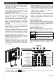
INTRODUCTION Multi-Function Transmitter Your system responds to signals sent by a 4-button (MCT- 234) or a 6-button two-way (MCT- 237) ‘keyfob’ transmitter, or by a two-way wireless keypad (MKP-150/151) - see figure 4. The MCT-234 keyfob transmitter is used to control single or multiple predefined partition(s) only. The MCT-237 keyfob transmitter and the two-way wireless keypad can control a single or any combination up to 3 partitions.
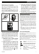
INTRODUCTION Proximity Tags When Partition is Disabled Your system responds to valid proximity tags enrolled to the system. The proximity tag enables you to perform a variety of functions without entering user code, for example, arming, disarming, reading the event log, etc. Whenever the user code is required, you can simply present a valid proximity tag and perform the desired operation without the need to key-in your user code.
SECURING THE PROTECTED SITE 2. Securing The Protected Site Security-Related Pushbuttons Key Function Arming when nobody is at home Arming when people remain at home Canceling the entry delay upon arming (‘AWAY-INSTANT’ or ‘HOME-INSTANT’) Disarming the system and stopping alarms Partition selection Partition selection process IMPORTANT NOTE: Partitioning refers only to purchased control panels that support the partitioning feature.
SECURING THE PROTECTED SITE Switching from ‘HOME’ to ‘AWAY’ Do not disarm the system - just press . The response will be the same as in ARMING AWAY above. Vacate the premises before the exit delay expires. ARM indicator lights during the armed state. If you wish to arm HOME-INSTANT, proceed as follows: PRESS ARMING HOME ARMING INSTANT (alternating) Switching from ‘AWAY’ to ‘HOME’ Do not disarm the system - just press .
SECURING THE PROTECTED SITE Arming in the Latchkey Mode This mode is useful for a parent at work who wants to be sure that his children have returned from school and have disarmed the system. Arming in the “latchkey” mode means that a special “latchkey” message will be sent out when the system is disarmed by a “latchkey user”. Latchkey users are holders of user codes 5 through 8 or users of Keyfob transmitters 5 through 8.
SECURING THE PROTECTED SITE To read the alarm memory, refer to Chapter 5. The "MEMORY" message will disappear only upon re-arming the system. C.
SPEECH AND SOUND CONTROL 3. Speech And Sound Control (In PowerMaxComplete that does not have VOICE option, the SPEECH and VOICE features are not applicable, only the CHIME feature is applicable). PRESS RESULTANT DISPLAY VOLUME– (max) VOLUME– Speech & Sound Cont. Push-buttons The sound and speech-related functions offered by the PowerMaxComplete are controlled with the keypad, as detailed in the following list.
SPEECH AND SOUND CONTROL When you release the button, the display will revert to the normal status-displaying mode, but will also indicate that a message is waiting. For example: READY HH:MM (alternating) READY MSG To check your own message, listen to it within one minute from the end of recording (see Chapter 3 Message Playback). This way the MSG indication will not be erased.
ELECTRICAL APPLIANCE CONTROL 4. Electrical Appliance Control Control Options and Pushbuttons Automatic ON/OFF Control The system allows manual or automatic remote control of a device connected to the PGM output. The user defines the ON and OFF times via the Scheduler (see Chapter 7 - Scheduler Function). The installer determines which zone sensors will switch the remote controlled appliances on and off.
READING ALARM MEMORY AND TROUBLE DATA 5. Reading Alarm Memory And Trouble Data Reviewing Alarm/Tamper Memory The PowerMaxComplete retains in its memory alarm and “tamper” events that occurred during the last arming period. For PowerMaxComplete that includes partition option: In order to review alarm and tamper events of a specific partition, you need to select the desired partition(s), (please refer to Partition Selection Process in Chapter 2).
READING ALARM MEMORY AND TROUBLE DATA • AC Supply Failure - There is no power and the system is working on backup battery power (this trouble is reported 5 minutes after its occurrence). • System Jammed - A radio-frequency signal is blocking communication channel of sensors and control panel. • Communication failure - A message could not be sent to the central monitoring station or to a private telephone (or a message was sent but was not acknowledged).
SPECIAL FUNCTIONS 6. Special Functions Looking after People Left at Home An important characteristic of the PowerMaxComplete is its ability to function in a mode contrary to the usual behavior of an alarm system. When the system is in the disarmed state (or even when armed “HOME” with perimeter protection only), it can keep track of in-house activity and will report lack of motion in interior zones if there is no detection of motion within predetermined time limits.
SPECIAL FUNCTIONS B.
SPECIAL FUNCTIONS Important! If you wish to exit the two-way communication mode and execute another command, just press [ ] and then key your user code followed by the command (see “keying sequences” in Executable Commands table above). Reporting to Private Telephone control panel The PowerMaxComplete can be programmed by the installer for selective transmission of messages to private telephone subscribers.
SPECIAL FUNCTIONS Command Individual Partition SMS Format 1 Arm AWAY “AWAY ” or “AW ” 2 Arm AWAY instant “P# AWAY INST ” or “P# AWI ” 3 Arm AWAY Latchkey “AWAY INST ” or “AWI ” “LATCHKEY ” or “LK ” 4 Arm AWAY Latchkey instant “LATCHKEY INST ” or “LKI ” “P# LATCHKEY INST ” or “P# LKI ” 5 Arm HOME “HOME ” or “HM ” “P# HOME ” or “P# HM ” 6 Arm HOME instant “HOME INST ” or “HMI ” “P#
SPECIAL FUNCTIONS Note: During the test period, 24-hour zones will not cause an alarm if violated, but a fire zone will function normally. A typical test will take place as follows: A. Click . The display will read: WALK TEST B. Click the button, the display will prompt you for your user code: ENTER CODE ____ C. Enter your master user code. The siren will sound for 2 seconds and the display will change to: TESTING D.
USER SETTINGS 7. User Settings What are the Settings You Need? The installer provides you a ready-to-use alarm system, but a few settings and adjustments will still be needed. Note: Although the user settings are your responsibility, you may request your installer to perform them for you (except for the user codes, which you would like to keep secret).
USER SETTINGS READY 00:00 WALK TEST USER SETTINGS ENTER CODE _ _ _ _ [master/ user code] Instruction: Enter 4-digit master user code (default “1111”), or user code (see note below). These menu items are displayed only if “bypass” was enabled by the installer. RECALL BYPASS is applicable when Partition is disabled. * Menu items that are marked with an asterisk can be accessed only if master user code has been entered.
USER SETTINGS RESULTANT DISPLAY PRESS ACTION RESULTANT DISPLAY TO RECALL Z22: BYPASSED (alternating) LIVING ROOM TO CLEAR Z22: FUNCTIONAL RECALL BYPASS You may now select any other item on the USER SETTINGS menu or quit programming by clicking . When TO EXIT is displayed - click . (alternating) LIVING ROOM You may now click and then select any other item on the USER SETTINGS menu, or click to quit programming. When TO EXIT appears - click .
USER SETTINGS Setting the User Codes A maximum of eight 4-digit codes can be defined out of a total of (10)4 = 10000 user code possibilities. Having entered your Master User Code successfully (see above - Entering the User Settings Menu), click until the display reads: SET USER CODES User Code 1 replaces the factory default master user code, and should be assigned to the master user of the system. This code can not be erased.
USER SETTINGS READY 00:00 WALK TEST ENTER CODE _ _ _ _ [4-digit master/user code] (for checking state of next zone) (example) SET BYPASS (5) (5) SHOW BYPASS (5) RECALL BYPASS INSTALLER MODE USER SETTINGS (First display) Z01: OPEN TO BYPASS Z01: BYPASSED Alternating Alternating KITCHEN KITCHEN BYPASS LIST TO RECALL REPORT TO PRVT (3) PRIVATE REPORT (1) VOICE REPORT SMS REPORT TEL# disable report all all (-op/cl) all (-alerts) alarms alert
USER SETTINGS From drawing in previous page (1) SQUAWK OPTION (1) SET TIME&FORMAT US FORMAT - 12H if not satisfied EU FORMAT - 24H TIME _ _:_ _A TIME _ _:_ _ [time] e.g. 07:55P(4) TIME 07:55 P SET DATE&FORMAT DATE DD/MM/YYYY Moving forward Show / confirm data Moving backward if not satisfied DATE MM/DD/YYYY DATE:_ _/_ _/_ _ _ _ (date)(2) (e.g. 30/12/2007) Moving one level up in the menu Return to “ TO EXIT” (date)(2) (e.g.
USER SETTINGS Enrolling Keyfob Transmitters - Clicking Keyfob transmitters are multi-button wireless units of the CodeSecure™ type with up to 16 million ID codes combinations. Eight system users carry keyfob transmitters to exercise better, quicker and safer system functions control. Your control panel must recognize the unique identification code (ID) of each such keyfob to respond to commands transmitted by them.
USER SETTINGS D. Present the tag to the control panel left bottom side. In response, the “Happy Tune” (- - - –––) will sound and the display will change to: Tag No: 1 A dark box will appear at the far right, indicating that the chosen tag has been enrolled. and enroll the next proximity E. Click tag (2, 3,...8), as described in step D. F. From this point on, you may continue in several different directions: • If you wish to enroll another tag, select the desired number by: - Clicking to go up (6 7 8.....
USER SETTINGS You may now select any other item on USERS SETTINGS menu or quit programming process by clicking . When " TO EXIT" is displayed, click . Setting Arming Time Having entered your Master User Code successfully (see above - Entering the User Settings Menu), click button (repeatedly, if necessary) until the display will read: AUTO ARM TIME From here, proceed as follows: PRESS RESULTANT DISPLAY arm time_ _ : _ _ A [time digits] (e.g.
USER SETTINGS Setting the Date and Date Format Scheduler Function Having entered your Master User Code successfully (see above - Entering the User Settings Menu), click button (repeatedly, if necessary) until the display will read SET DATE&FORMAT. From here, proceed as follows: PRESS RESULTANT DISPLAY The Scheduler enables to start and stop activity of the desired devices.
READING THE EVENT LOG 8. Reading The Event Log Event Log Description Because of the limited display space, the event description is shown first, then the date and time. The two displays are shown alternately several to move on to an times, until you click older event, or until the “no action” 4-minute timeout restores the system to the normal operating mode. Access to the event log is provided by clicking the asterisk ( ) key and then keying your master user code.
MAINTENANCE 9. Maintenance Replacing the Backup Battery The PowerMaxComplete uses regular electrical supply, but incorporates backup 9.6V battery pack (see sticker on battery cover). It is important to replace it immediately upon receiving the following trouble message when reviewing system troubles (see Chapter 5 - Reviewing Trouble Information): CPU LOW BATTERY Replacing Wireless Devices Batteries Front unit Battery cable Figure 10. Battery Replacement Open battery compartment cover.
MAINTENANCE Periodic Testing Cleaning the Control Panel The components of your security system are designed to be maintenance-free as much as possible. Nevertheless, it is mandatory to perform a “walk test” at least once a week and after an alarm event to verify that all system detectors function properly. Proceed as described in Chapter 6 Conducting a Walk-Test, and If there is any problem, notify your installer at once.
PERFORMANCE LIMIT 10. Performance Limits Although the alarm control system you purchased is highly reliable, it does not guarantee protection from burglary and fire hazards. Even the most advanced systems can be defeated or might occasionally fail to warn. Some of the reasons for this are: Sloppy maintenance: If the system is used over a long period of time without testing, a key element such as a detector or a siren might go wrong without any visible or audible signs of failure.
APPENDICES APPENDIX A. PARTITIONING PowerMaxComplete includes an optional partition feature. Partitioning is available only if your installer has enabled the feature. Once partitioning is enabled Partitioning menus are added to the system which can be viewed on the control panel's LCD display. Partitioning allows you to divide the system into three independently controllable areas with different users assigned to each partition whereby each user can arm the partition to which they are assigned.
APPENDICES Siren A partition is alarmed when receiving an event from an alarmed device assigned to that partition. Alarmed devices do not affect partitions to which they are not assigned. A siren is common to all partitions; therefore, an alarm from one or more partitions will activate the siren. • Siren Activity • The siren will be activated when receiving an event from an alarmed device. Overlapping siren activations from different partitions will not cause the duration of the siren to be extended.
APPENDICES MCM-140+ MCM-140+ The wireless remote commander is used to control single or all partitions. Arming/Disarming All Partitions To arm all partitions, press the HOME / AWAY / DISARM button followed by the user code. Arming/Disarming a Single Partition To arm/disarm a single partition, press the "LIGHT" button followed by the desired partition number (1, 2 or 3). When the red LED turns OFF, press the HOME/AWAY/DISARM button within 5 seconds followed by the user code.
APPENDICES APPENDIX B. GLOSSARY This list of terms is arranged in alphabetical order. Any term indicated by cursive (italic) letters within the explanatory text can be looked up separately. Abort Period: When an alarm is initiated, the internal sounder is activated first for a limited period of time which is the abort period set by the installer.
APPENDICES Latchkey: The Latchkey mode is a special arming mode in which designated "latchkey users" will trigger a "latchkey message" to be sent to a telephone when they disarm the system. Note: This applies to latchkey users 5 to 8 only For example, if a parent wants to be sure that their child has returned from school and disarmed the system. Latchkey arming is only possible when the system is armed in the AWAY mode.
APPENDICES APPENDIX C. HOME FIRE ESCAPE PLANNING Fire can spread rapidly through your home, leaving you a short time to escape safely. Your ability to get out depends on advance warning from smoke detectors and advance planning - a home fire escape plan that everyone in your family is familiar with and has practiced. • Pull together everyone in your household and make an evacuation plan. • Draw a floor plan of your home, showing two ways out of each room, including windows.
FCC STATEMENT Industry Canada Customer Information The 315 MHz model of this device complies with Part 15 of the FCC Rules. Operation is subject to the following two conditions: (1) This device may not cause harmful interference, and (2) this device must accept any interference that may be received, including interference that may cause undesired operation.
W.E.E.E. Product Recycling Declaration For information regarding the recycling of this product you must contact the company from which you orignially purchased it. If you are discarding this product and not returning it for repair then you must ensure that it is returned as identified by your supplier. This product is not to be thrown away with everyday waste. Directive 2002/96/EC Waste Electrical and Electronic Equipment. VISONIC LTD. (ISRAEL): VISONIC INC. (U.S.A.): VISONIC LTD.
©Visonic LTD.