
Installation Instructions Part 2

16 DE5468IP
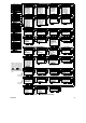
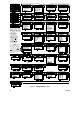
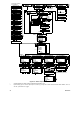
4.4.21 “Not Active” (fig. 4.4, location 21)
Here you determine the time limit for reception of signals
from sensors used to monitor the activity of sick, elderly or
disabled people. If no device detects and reports
movement at least once within the defined time limit, a
“not-active” alert is initiated.
Options: 3, 6, 12, 24, 48, 72 hours and no act disable.
4.4.22 Back Light (fig. 4.4, location 22)
Here you determine whether the keypad back lighting will
remain on at all times or will come on when a key is
pressed and go off within 10 seconds if no further
keystrokes are sensed.
The two options are: always on and off after 10 s.
4.4.23 Duress (fig. 4.4, loc. 23)
A duress alarm (ambush) message can be sent to the
central station if the user is forced to disarm the system
under violence or menace. To initiate a duress message,
the user must disarm the system with the duress code
(2580 by default). Here you can change the code digits or
enter "0000" to disable the duress feature. The system
does not allow the user to program the duress code
saved in this memory location as an existing user code.
4.4.24 Piezo Siren (fig. 4.4, location 24)
Here you determine whether the internal siren will sound or
remain silent upon alarm (according to the user
preference). Options: piezo siren on, piezo siren off.
4.4.25 Reset Option (fig. 4.4, location 25)
(Not applicable in the USA)
Here you determine whether the system can be rearmed
(after an event) by the user or only by the installer.
Options: user reset or engineer reset.
If Engineer Reset is selected, the system can be rearmed
only by the installer
; by entering and exiting the installer
menu, by entering and exiting the event log (see section 7),
or by remote telephone. To perform Engineer Reset via the
telephone, establish communication with the PowerMax Pro
(see user guide, par. 6.3A, steps 1-5) and continue as
follows:
a. [*], [installer code], [#]
b. Wait for 2 beeps
c. [*], [1], [#]
d. [*], [99], [#]
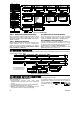
4.4.26 Tamper Option (fig. 4.4, location 26)
Here you determine whether zone tamper will be reported
or ignored. Available options are: zone tamper ON and
zone tamper OFF.
4.4.27 Siren On Line (fig. 4.4, location 27)
Here you determine whether the siren will be activated or not
when the telephone line fails during system armed state.
Available options are: enable on fail, disable on fail.
4.4.28 Memory Prompt (fig. 4.4, location 28)
Here you determine whether the user will receive
indication that an alarm has been activated.
Available options are: enable and disable.
4.4.29 Disarm Option (fig. 4.4, location 29)
Here you determine when it is possible to disarm the system:
A. Any time.
B. In AWAY mode, during entry delay, by using the
PowerMax Pro keypad or wireless device (keyfob).
C. In AWAY mode, during entry delay, by using a wireless
device (keyfob) only (this is set as a default in UK to
comply with DD423).
D. During entry delay, or by using the PowerMax Pro
keypad in AWAY mode.
Options: any time, on entry all, on entry wireless, or
entry + away kp.
4.4.30 Bell/Rep. Option (fig. 4.4, location 30)
Here you determine whether an alarm will be initiated
(siren / report) when there is a supervision / jamming
failure during AWAY arming state.
Available options are: EN standard and other. When "EN
standard" is selected, if there is supervision / jamming
failure during AWAY arming, the siren is activated and the
events are reported as tamper events. When "Other" is
selected, there is no such activity during AWAY arming.
4.4.31 Low-Bat Ack (fig. 4.4, location 31)
Here you determine whether the user will hear or will not
hear low battery sound when he tries to disarm the system
with a keyfob whose battery voltage is low.
Available options are: keyfob L-B on (the user has to
acknowledge the keyfob low battery message) or keyfob
L-B off (the user does not have to acknowledge the keyfob
low battery message).
4.4.32 Screen Saver (fig. 4.4, location 32)
Here you can determine that if no key is pressed during
more than 30 seconds, the display will be “PowerMax” (to
prevent possible intruder of knowing the system status).
You can determine that normal display will return after
pressing the
button followed by entering user code
(Refresh by Code) or after pressing any key (Refresh by
Key).
If Refresh by Key is selected, the first pressing of any key
(except Fire and Emergency) will cause normal display
return and the second press will perform the key function.
Regarding the Fire and Emergency keys, the first key
press will cause normal display return and also will perform
the Fire/Emergency function.
Options: scrn saver OFF, refresh by code, refresh by key.
4.4.33 Confirm Alarm (fig. 4.4, location 33)
Here you determine that if 2 successive alarms will occur
during a specific period, the second alarm will be
considered as a confirmed alarm (for confirmed alarm
reporting, see par. 4.5.12 REPORT CNF ALARM).
Options: disable 30 min., 45 min., 60 min., or 90 min.
4.4.34 AC FAIL REP (fig. 4.4, location 34)
Here you determine the time interval between AC power
failure occurrence and the failure reporting. Options: 5
minutes, 30 minutes, 60 minutes or 180 minutes.
4.4.36 User Permission
(fig. 4.4, location 36)
Here you determine whether the access to the INSTALLER
MODE requires user permission. If you select ENABLE, the
installer mode will be accessible only through the user
menu after entering the user code.
Options: Enable, Disable.