
User Manual

D-303089 SR-720 PG2 Installation Instructions 1
SR-720 PG2
Wireless PowerG Indoor Siren
Installation Instructions
1. INTRODUCTION
The SR-720 PG2 is a full 2-way wireless PowerG indoor siren, designed for installation in areas in which wiring action is difficult or impossible.
Features
Siren and strobe light activation: When an identified event message is received from the compatible PowerG alarm system, the siren
activates its sounder & strobe light.
Notes:
The sounder is activated for a predefined "Bell Time" (refer to the control panel Installer Guide), according to local authorities requirements, or
until the system is disarmed, whichever occurs first.
The strobe light operates as described in the control panel Installer Guide.
Tamper indication: In case of tamper while the system is armed, the siren transmits the message to the alarm system and then the alarm
system determines whether the siren should be activated or not. If the siren does not receive an acknowledge message from the alarm system,
the siren will function independently.
Low battery voltage alert: When the battery voltage is low, a low battery message is sent to the alarm system. After the low voltage message
delivery, at least 2 siren alarms are possible before the siren is totally inactive.
Power Supply: Non-rechargeable battery.
Sound Types: Burglar, fire, gas/Co and flood.
Entry/Exit: Exit delay beeps sound once the user has armed the system. Entry delay beeps sound once the user has entered the protected
area. (Entry/exit beeps can be enabled / disabled from the control panel Installer menu.)
Squawk indications: Squawk (beep) sounds can be used to indicate alarm system arming (1 squawk) and disarming (2 squawks) by a keyfob
(squawk can be enabled from the control panel User menu).
Double Tamper protection: When the siren front panel is removed or when the siren is removed from the wall, tamper alarm is sent to the
alarm system.
2-way full supervision
The siren is a fully supervised, 2-way communication device. It includes a receiver, to receive event messages
from the alarm system, and a transmitter, to periodically transmit its status signal to the alarm system.
Self-test feature
Upon pressing the self test switch, siren functional check is performed - low level sounds and flash light indicate
that the siren is serviceable.
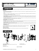
Fig. 1 - External View
2. INSTALLATION
2.1 Installation
1
2
3
(*)
4
5
A
B
A
A
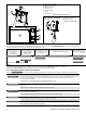
1. Open plastic cover screw.
2. Using Philips screwdriver, remove screw and remove cover.
3. Mark for drilling.
4. Drill 4 holes.
5 Fasten with 4 screws.
A. Mounting surface.
B. For back tamper screw.
Figure 2: Installation