
Specifications

D-304046 TOWER-20 PG2 Installation Instructions 1
TOWER-20 PG2
PowerG,WirelessHigh‐securityPIRMotionOutdoor
MirrorDetectorwithAnti‐masking
Installation Instructions
1. INTRODUCTION
The TOWER-20 PG2 is a 2-way, wireless outdoor digital mirror PIR detector which includes the following features:
Patented 8 independent quad PIR detectors (Octa-QUAD) operating in true Quad configuration (patented) with true
motion recognition (TMR) processing for each of the 8 PIR detectors, as well as central motion processing that
distinguishes between moving intruders and trees and bushes in motion.
Advanced Obsidian Black Mirror
TM
optics (patent pending).
Optimum performance even in poor weather conditions such as snow, rain, dust, wind and direct sunlight
Tamper protection prevents opening and removal from wall
PowerG two-way Frequency Hopping Spread Spectrum FHSS-TDMA technology - provides robustness and reliability that
is closer than ever to wired systems
Built-in link quality indicators enable installer to check signal quality without physically approaching the control panel, thus
making installation faster and easier.
Robust housing with recessed window.
Smart anti masking distinguishes between masking spray and rain.
Alarm LED is visible in sunlight.
Automatic termination of walk-test after 15 minutes.
Microprocessor-controlled temperature compensation.
Immunity to pets weighing up to 18 Kg (40ib), not pet alley
Built-in swivel bracket
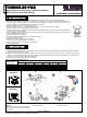
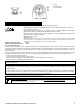
Figure 1.
General View
2. INSTALLATION
2.1 Installation
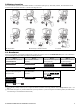
A. Bracket installation (see Figure 2). Fix the bracket firmly on a stable wall or pillar. The orientation of the fixed bracket must be as parallel as
possible to the surveyed ground surface.
B. Adjust the detector's horizontal and vertical angles (see Figure 3), according to the surveyed ground surface. The vertical angle indicator
position for various installation height and coverage distance combinations is detailed in Table 1 (the information refers to a relatively flat
surveyed area. Verify the vertical adjustment by walk-test).
C. Fasten the detector to the bracket (see Figure 2 step 4).
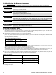
Table 1 - Vertical Adjustment Reference
Mounting Height
Coverage Distance
2m / 6.7ft 4m / 13ft 6m / 20ft 8m / 26ft 10m / 33 ft 12m / 39 ft
3.0m / 10 ft - 1 2 2 3 3
2.5m / 8 ft 1 1 2 3 4 4
2.0m / 7 ft 1 2 3 4 5 5
1.5m / 5 ft 2 3 4 5 - -
Correct
Installation
Incorrect
Installation
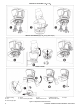
A. Mark drilling point B. For wall tamper C. Drill
D. Fasten
Note: The 2 screw holes enable adjustment
of the bracket on the wall, if needed, following
the walk test.
E. Three long screws F. Two short screws
Figure 2 - Installation