
Specifications

D-301524 1
TOWER 20 AM
Outdoor Octa-Quad™ Mirror Detector with Anti-Mask
[Grade 3]
Installation Instructions
1. INTRODUCTION
Detector's Features
• Patented 8 independent quad PIR detectors (Octa-QUAD™) operating in
true Quad configuration with true motion recognition (TMR) processing
for each of the 8 PIR detectors and central motion processing - can
distinguish between a moving intruder and moving trees and bushes.
• Advance Obsidian Black Mirror
TM
optics (patent pending).
• High protection against snow, rain, dust, wind and direct sunlight.
• Tamper protection against opening and removal from wall.
• Alarm LED is visible in sunlight.
• Low voltage detection
• Self test
• Day & night or night only setting.
•
Robust housing with recessed window.
•
Smart anti masking can distinguish
between masking spray and rain.
•
Immunity to pets weighing up to 18 Kg
(40lb), not pet alley.
• Built in swivel bracket.
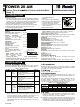
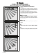
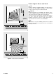
LEDS
Figure 1 -
TOWER 20 AM
2. SPECIFICATIONS
OPTICAL
Black Mirror Max. Coverage: At
least 12 meters (40 ft)/90º.
Detector Technology: 8
independent quad PIR detectors
operating in true Quad
configuration.
Pet- immune: Up to 18Kg (40lb.)
ELECTRICAL
Input Power: 8-16VDC
Standby Current:
15mA@12VDC.
Supply Current: 70 mA max.
(red and yellow LEDs light
steadily)
Low Voltage Detection: If
input voltage is below 7.5 VDC
Outputs:
Alarm output: Solid State
Relay. NC, 100 mA / 30 V, 35
ohm maximum internal
resistance. (see Table 4).
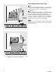
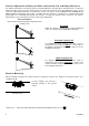
SIDE VIEW OF
EACH DETECTOR
36912 m0
2.4 m
(8 ft)
10 20 30 40 ft
TOP VIEW
90°
0
3m (10ft)
6m (20ft)
9m (30ft)
36912 m0
10 20 30 40 ft
3m (10ft)
6m (20ft)
9m (30ft)
Fig. 2 - Coverage pattern
Trouble output: Solid State Relay. NC, 100 mA / 30 VDC, 35 ohm
maximum internal resistance.
(see Table 4).
Tamper output: NC switch, 50mA / 30 VDC. "Open" by opening
detector’s cover or removing it from mounting surface.
Masking detection delay: 120 sec.
Remote LED enable input (TST): High impedance input. Affects
LEDs operation only if internal LEDs selector is set to OFF.
MOUNTING
Mounting type: Wall mounting
Mounting height: 1.5 - 3.0 meters (5 – 10 ft)
Vertical adjustment: 0º to -10º, in 2.5º steps.
Horizontal adjustment: -45º to +45º, in 5º steps.
ENVIRONMENTAL
Operating Temperature: -35°C to 60°C (-31°F to 140°F)
Storage Temperature: -35°C to 60°C (-31°F to 140°F)
Humidity: 95% max.
White light immunity: Above 25000 lux
PHYSICAL
Dimensions (height x length x width: 157x147x124mm (6-3/16 x 5-13/16
x 4-7/8").
Weight: 600g (21 oz)
Color: White or gray
STANDARDS COMPLIANCE
(FCC) CFR 47 Part 15, EN 50130-4, EN 60950, EN 50130-5
Environmental class IV. IP 55.
US Patents: 7250605, 6818881, 5693943. Other patents pending.
3. INSTALLATION
3.1 DIP Switches Setup
Remove the 2 detector's bottom covers (see Figure 3, steps 4-8) to gain
access to the DIP switches. Set the DIP switches, according to Table 1:
Table 1 – DIP Switch Setup
DIP SW # Function Description Default
1
LEDs
OFF/ON
OFF: Motion and masking alarm LEDs
is disabled (OFF). Can be enabled by
TST input (Active "low")
ON: Motion and masking alarm LEDs
is enabled (ON).
ON
2
24H / night
only
OFF: Motion alarms are always
enabled (24 hours).
ON: Motion alarms are enabled only
at dark (night).
OFF
3
AM ON /
OFF
ON: AM on
OFF: AM off
*
ON
OFF: masking event reported to panel
as TROUBLE (Trouble relay opens).
4
Masking
event opens
Alarm relay
(EN
standard)
ON: masking event reported to panel
as TROUBLE and ALARM (EN
standard). Trouble and Alarm relay
opens at the same time.
**
OFF
* Switching from OFF to ON resets the detector for a stabilization
period of 60 sec. and causes the detector to re-adapt to its
current surroundings. Remain at a distance of at least 0.5 m (1.5
ft.) from the detector to prevent disruption of this process.
** Use ON for EN approved control panels / installations. However,
many installers prefer not to have the ALARM relay opened on a
masking event.
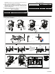
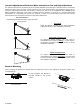
3.2 Installation
Bracket installation (see figure 3) – firmly fix the bracket on a stable
wall or pillar. The orientation of the fixed bracket should be as parallel
as possible to the surveyed ground surface.
3.3 Wiring
Perform wiring (see figure 3, step 8 - 10)
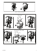
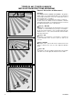
3.4 Adjustments
Adjust detector's horizontal and vertical angles (see Fig. 4, steps 1 - 6),
according to the surveyed ground surface and close the detector, as
shown in Fig. 3, steps 7 - 12.
The vertical angle indicator position for various installation height and
coverage distance combinations is detailed in Table 2 (the
information refers to a relatively flat surveyed area. however, in any
case the vertical adjustment should be verified by walk-test).
Table 2 - Vertical Adjustment Reference
Coverage Distance
Mounting
Height
2m / 6.7ft 4m / 13ft 6m / 20ft 8m / 26ft 10m / 33 ft 12m / 39 ft
3.0m / 9,8 ft - 1 2 2 3 3
2.5m / 8,2 ft 1 1 2 3 4 4
2.0m / 6.7 ft 1 2 3 4 5 5
1.5m / 4.9 ft 2 3 4 5 - -
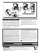
3.5 Test
A. Set the detector in Walk-Test mode, by setting DIP switch 1 (LEDs
ON/OFF) to ON position (see Fig. 3, steps 10 and 11), or activate
the remote TST input by connecting it to GND.
B. Walk into the detector's field of view at the expected far edge of the
coverage area. Verify that each time your motion is detected the red
LED lights for 2 seconds and the control panel receives the alarm. If
required, perform detector's horizontal / vertical readjustments.