SHERWOOD INDUSTRIES IS AN ENVIRONMENTALLY RESPONSIBLE COMPANY. THIS MANUAL IS PRINTED ON RECYCLED PAPER. PLEASE KEEP THESE INSTRUCTIONS FOR FUTURE REFERENCE PELLET STOVE VF 100A Freestanding & Fireplace Insert OWNER’S MANUAL Contact your building or fire officials about restrictions and installation inspection requirements in your area. PLEASE READ THIS ENTIRE MANUAL BEFORE INSTALLATION AND USE OF THIS PELLET BURNING ROOM HEATER.
Table of Contents Introduction..............................................................................................................................3 Rating Label Location......................................................................................................3 Pellet Quality..................................................................................................................3 Important Safety Data..............................................................................
Introduction RATING LABEL LOCATION: Freestanding: The rating label is located on the inside of the hopper lid. Insert: The rating label is located on the hopper cover. PELLET QUALITY: Pellet quality is important, please read the following: Your Vista Flame pellet stove has been designed to burn wood pellets only. Do not use any other type of fuel, as this will void any warranties stated in this manual.
Introduction IMPORTANT SAFETY DATA: Please read this entire Owner’s Manual before installing or operating your Vista Flame Pellet Stove. Failure to follow these instructions may result in property damage, bodily injury or even death. Contact your local building or fire official to obtain a permit and any information on installation restrictions and inspection requirements for your area.
Introduction ELECTRICAL: The use of a surge protected power bar is recommended. The unit must be grounded. The grounded electrical cord should be connected to a standard 115 volts (4.5 Amps), 60 hertz electrical outlet. Ensure the polarity to the outlet, the unit will be plugged into, is correct as incorrect polarity can affect the unit’s operation. Be careful that the electrical cord is not trapped under the appliance and that it is clear of any hot surfaces or sharp edges and also must be accessible.
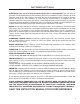
Specifications DIMENSIONS - FREESTANDING: 23 3/4" (603mm) 22" (559mm) 34 1/8" (867mm) 24 7/16" (621mm) 24 3/8" (620mm) Figure 1: Dimensions of VF100 Freestanding. DIMENSIONS - INSERT: Regular Panel 40" (1016mm) Oversized Panel 46" (1158mm) 22" (559mm) 23 5/8" (601mm) 12 5/8" (322mm) Regular Panel 30 1/8" (766mm) Oversized Panel 32 7/8" (835mm) 22 3/4" (579mm) 22 3/4" (579mm) 1 3/8" (34mm) Figure 2: Dimensions of VF100 Insert.
Operating Instructions CONTROL BOARD FUNCTIONS: 1. AUGER LIGHT: This green light will flash in conjunction with the auger pulse. 2. MODE LIGHT: Responsible for signaling the state of the control board. When the light is flashing the stove is in an automatic start mode or the thermostat has control of the unit. When the light is solid, the Heat Level Setting can be altered. 3. THERMOSTAT SWITCH: Used to set the unit’s controls to one of three mode settings; manual, high/low, or auto/off. 4.
Operating Instructions If this is the first time the unit has been started or the unit has run out of fuel, the auger will need to be primed. This can be done by restarting the unit five (5) minutes into its start-up or by putting a small hand full of pellets into the burnpot. To OPERATE: When a fire has been established, the System Light will turn solid (after approximately 10 - 15 minutes) and the Auger Light will continue to flash to the corresponding Heat Level setting.
Operating Instructions The easiest way to make sure that an efficient flame is achieved is to understand the characteristics of the fire. • A tall, lazy flame with dark orange tips requires more air – Open slider (pull out) slightly. • A short, brisk flame, like a blowtorch, has too much air – Close slider (push in) slightly. • If the flame is in the middle of these two characteristics with a bright yellow/orange, active flame with no black tips then the air is set for proper operation, refer to Figure 7.
Routine Cleaning and Maintenance NOTE: Do not use abrasive cleaners to clean the surface or any part of the stove.
Routine Cleaning and Maintenance ASH PAN (2-3 days) Monitor the ash level every week. Remember that different pellet fuels will have different ash contents. Ash content is a good indication of fuel efficiency and quality. Refer to “Warnings and Recommendations” for disposal of ashes. DO NOT PLACE UNBURNED OR RAW PELLET FUEL IN ASH PAN. Dump the ashes into a metal container stored away from combustibles. Monitor the ash level every week. Remember that different pellet fuels will have different ash contents.
Routine Cleaning and Maintenance Installation of firebox backing: • Install the side panels in place. Insert center panel, hold the panels in place • Install the top rod by sliding it into one side panel then across into the other panel. Screw rod in place. • Re-install steel brick liner and screw in place. • Replace top baffle EXHAUST VENT (season) The products of combustion will contain small particles of flyash.
Installation DECIDING WHERE TO LOCATE YOUR PELLET APPLIANCE: 1. Do not install the stove in a bedroom or room where people sleep in. 2. Locate the stove in a large and open room that is centrally located in the house. This will optimize heat circulation. 3. Check clearances to combustibles and for the least amount of interference to house framing, plumbing, wiring, etc. 4. You can vent the stove with approved pipe through an exterior wall behind the unit or pass it through the ceiling and roof.
Installation Remove the two (2) screws from the backside of the pedestal. Remove the two (2) screws from inside the pedestal. Figure 11: Screws to take out to remove insert unit from pallet. Figure 10: Screws to take out to remove freestanding unit from pallet. INSTALLATION OF PEDESTAL - INSERT: The Fireplace Insert model come with a pedestal that has to be attached prior to installation: 1. Remove the unit from the box. 2. Remove the pedestal from the hopper. 3.
Installation CLEARANCES TO COMBUSTIBLES - FREESTANDING: Back Wall Side Wall 1" (25mm) Ad ja ce 1" (25mm) nt When installing this unit on a combustible floor (for example linoleum, hardwood flooring) a non-combustible hearth pad must be under the unit. The pad must extend at least the width of the appliance [22” (558 mm)] and at least the depth of the appliance plus 6” (153 mm) in front of the appliance [301⁄2” (775 mm)].
Installation OUTSIDE FRESH-AIR CONNECTION: Outside fresh air is mandatory when installing this unit in airtight homes and mobile homes. When connecting to an outside fresh air source, do not use plastic or combustible pipe. A 15⁄8” minimum (42 mm) ID (inside diameter) steel, aluminum or copper pipe should be used. It is recommended, when you are installing a fresh air system, to keep the number of bends in the pipe to a minimum.
Installation VENT TERMINATION REQUIREMENTS: IT IS RECOMMENDED THAT YOUR PELLET STOVE BE INSTALLED BY AN AUTHORIZED DEALER/INSTALLER. Table 1: Use in conjunction with Figure 19 for allowable exterior vent termination locations. Letter Minimum Clearance A 24 in (61 cm) B 48 in (122 cm) Beside/below any door or window that may be opened. (18” (46 cm) if outside fresh air installed.) C 12 in (30 cm) Above any door or window that may be opened. (9” (23 cm) if outside fresh air installed.
Installation MOBILE HOME INSTALLATION - FREESTANDING: ● Secure the heater to the floor using the two holes in the pedestal. ● Ensure the unit is electrically grounded to the chassis of your home (permanently). ● Do not install in a room people sleep in. ● Outside fresh air is mandatory. Secure outside air connections directly to fresh air intake pipe and secure with three (3) screws evenly spaced.
Installation HORIZONTAL EXHAUST THROUGH WALL INSTALLATION - FREESTANDING: Vent installation: install vent at clearances specified by the vent manufacturer. A chimney connector shall not pass through an attic or roof space, closet or similar concealed spaces, or a floor, or ceiling. Where passage through a wall or partition of combustible construction is desired, the installation shall conform to CAN/CSA-B365 Installation Code for Solid-Fuel-Burning Appliances and Equipment.
Installation 10. The pipe must extend at least 12” (30 cm) away from the building. If necessary, bring another length of pipe (PL type) to the outside of the home to connect to the first section. Do not forget to place high temperature silicone around the pipe that passes through the thimble. 11. Install a vertical pipe, or if all requirements for direct venting are met, install vent termination. The stainless steel cap termination manufactured by the vent manufacturer is recommended.
Installation INSIDE VERTICAL INSTALLATIONS - FREESTANDING: 1. Choose a stove location that is ideal. See the section “DECIDING WHERE 2. Place a non-combustible hearth pad where necessary. 3. Place the unit on the hearth pad (if installed on a carpeted surface) and space the unit in a manner so when the pellet vent is installed vertically, it will be 3” (7.6 cm) away from a combustible wall. 4. Locate the center of the fresh air intake pipe on the unit.
Installation Rain cap Flashing 24" (61 cm) 3" (7.5 cm) Clearance 2" (5 cm) Support bracket Tee with cleanout ���� ��� 6" (15 cm) Type "L" vent ��������� ������ ����� ����� �� �������� Fresh air intake �������� �� ����� �� ��������� ����� ����� Non-combustible floor protection. Existing floor (combustible) Figure 27: Outside Vertical Installation.
Installation Rain cap Storm collar Seal plate (cover plate) Existing masonry flue Vent pipe (single wall stainless flex pipe or solid PL vent) Flexible vent connector (use this 5 foot [152cm] section of pipe to vent past fireplace damper or small shelf) Fireplace damper location Clean out tee Existing fireplace Figure 29: Freestanding hearth mount installation overview. MASONRY FIREPLACE INSTALLATION - FIREPLACE INSERT: The fireplace insert model requires a surround panel and a pedestal.
Installation Rain Cap Fresh-air intake Steel Plate or Flashing Flexible or Rigid 6" Stainless Steel Liner Damper Removed or Fastened Open Flexible stainless steel pipe connection Mantel Minimum 8" (20 cm) from top of stove Surround Panel 4. Connect a tee or 90° degree elbow to the exhaust pipe. 5. This fireplace insert must be installed with a continuous chimney liner of 3” or 4” diameter extending from the fireplace insert to the top of the chimney.
Installation INSTALLATION INTO FACTORY BUILT FIREPLACES: When installing the fireplace insert into a zero clearance fireplace, DO NOT cut or modify any factory firebox parts. If the fireplace insert does not fit into a zero clearance fireplace, we recommend you use a freestanding model and install as a hearth mounted unit. Install a 3” (76 mm) flex pipe from the stove to the top of the chimney (see “HEARTH MOUNT INSTALLATION - FREESTANDING:”). 1.
Installation INSTALLATION AND REMOVAL OF THE SURROUND PANELS - INSERT: 1. Attach one side trim to the top trim, using a corner bracket (see Figure 33) to secure pieces together. There are two (2) main pieces to each corner bracket (see Figure 34). When installing the corner pieces into the trim, the “B FACE” sides must face each other and the screw heads are to face out.
Installation THERMOSTAT INSTALLATION: 1. Install the wall thermostat (12 or 24 Volt rated) in a location that is not to close too the unit but will effectively heat the desired area. 2. Connect the Thermostat or Timer using a 2 x 18 gauge wire from the unit to the thermostat. Remove jumper wire and install thermostat wires here. If the heat in the room becomes to great, the high limit switch may turn the stove off and the switch will have to be manually reset.
Troubleshooting DO NOT: ● Hold the ON / OFF BUTTON down for circuit board model or hold the start-up switch down for timer control. This is a momentary contact switch and can be damaged if held down too long. ● Service the stove with wet hands. The stove is an electrical appliance, which may pose a shock hazard if handled improperly. Only qualified technicians should deal with possible internal electrical failures. ● Remove any screws in the firebox without first lubricating them with penetrating oil.
Troubleshooting « Exhaust Temperature Sensor failure – Bypass sensor located on Exhaust Blower. If stove now operates properly, the unit may require cleaning or a new sensor. Contact your local dealer for service. « Check the Heat Level Indicator if a fire is not detected, or if the fire has gone out the #3 light will flash because the Exhaust Temperature Sensor’s contacts have opened. « Check the Exhaust Blower voltage across the blower wires (>=114V on #5 setting and >= 52V on #1 setting).
Troubleshooting 9. The stove will not shut off. ü If the unit will not shut off, ensure that the thermostat (if equipped) is turned down below the room temperature (thermostat mode in the ON / OFF position). ü If the unit is in the HI/LOW mode the unit will not shut off but will go to an idle setting (LOW). Press the ON/OFF button to turn the unit off. ü Disconnect one of the brown wires from the exhaust temperature sensor. If the unit continues to operate, contact your local dealer for service. 10.
Wiring Diagram Armor Cable Supplied Optional Exterior Exhaust Blower Grey Grey Black Combustion Blower Vacuum Switch White White Blue Brown Exhaust Temperature Sensor Power Cord Brown Ground Thermostat 5 Amp Fuse Black White Orange Orange Purple Blue Yellow Red Grey Grey Brown Brown Red Red 115V White 220V Blue 115V Black 220V Brown Connect Thermostat Here Hot Red White Black Black Common Ignitor Convection Temperature Sensor Purple White Yellow White Orange Orange Convection Blower
Parts List Reference Number 1 2 3 4 5 6 7 8 9 10 11 12 13 14 15 32 Description Exhaust Temperature Sensor 120°F (60°C) Power Cord - 115V Auger Motor - 115V Convection Blower - 115V Convection Blower Impeller Convection Blower Insulator (Gasket) Combustion Main Impeller Combustion Cooling Impeller Combustion Blower Mounting Gasket Combustion Blower Housing Gasket Fan Temperature Sensor 160°F (71°C) Ignition Temperature Sensor 120°F (49°C) Ceramic High Limit Temperature Sensor 200°F (93°C) Manual Reset V
Parts List Reference Number 16 17 18 19 20 21 22 23 24 25 26 27 28 29 30 31 32 33 33 33 33 33 Description Auger Brass Bushings (Set of 2) Firebox Liner Top Plate 3⁄4” ID Auger Collar with Set Screw Knob 1 Inch Round Freestanding Back Grill Freestanding Hopper Lid With Handle Fireplace Insert Ash Pan Drawer With Latch Ash Sill Insert Hopper Cover Shoulder Bolt, Hardened Bush & Nut (Set of 2) Firebox Ceramic Wool Insulation Steel Brick Lining Freestanding Right Cabinet Side Freestanding Left Cabinet Side
Parts List Reference Number 33 33 34 35 36 37 38 39 40 41 42 43 44 45 46 47 48 49 34 Description Door Complete (Pre Jan 08) Door Complete (Post Jan 08) Insert Regular Trim Only - Brass Insert Regular Trim Only - Nickel Insert Oversized Trim Only - Brass Insert Oversized Trim Only - Nickel Freestanding Pedestal Complete Top - Freestanding Top - Insert Front Grill Bottom Grill Door Hinge Owner’s Manual Log Set Control Panel Door Control Panel Touch Latch Combustion Blower Exhaust Tube Combustion Blower
�� �� �� �������� ���� � ����� � ���������� �� � �� � �� � �� �� � � �� � � Parts Diagram - Components 35
Parts Diagram - Steel �� �� �� ����� � ����� ���������� �������� ���� �� �� �� �� �� �� �� �� �� �� �� �� �� �� �� �� �� �� � �� �� �� �� �� �� �� �� �� �� �� �� �� �� 36
Warranty Sherwood Industries Ltd. is the manufacturer of the VistaFlame line of heating products. At Sherwood Industries, our commitment to the highest level of quality and customer service is the most important thing we do. Each VistaFlame stove is built on a tradition of using only the finest materials and is backed by our Exclusive Lifetime Limited Warranty to the original purchaser. With VistaFlame, you’re not just buying a stove, you’re buying a company with years of unequalled performance and quality.
Warranty Exclusions and Limitations: 1. This Warranty does not cover tarnish, discoloration or wear on the plating or paint. 2. This Warranty excludes wear and tear or breakage caused by cleaning, moving or service on log set. 3. A qualified installer must install this stove or fireplace. This Limited Warranty covers defects in materials and workmanship only if the product has been installed in accordance with local building and fire codes; in their absence, refer to the owner’s manual.
Warranty 17. Damage to plated surfaces caused by fingerprints, scratches, melted items, or other external scores and residues left on the plated surfaces from the use of abrasive cleaners or polishes is not covered in this warranty. 18. The Limited Warranty does not cover tarnish, discoloration or wear on the plated surfaces. 19. The paint on the Metal Brick Liner may peel. This is due to the extreme conditions applied to the paint during normal usage. It is not a flaw and is not covered under warranty. 20.
Installation Data Sheet The following information must be recorded by the installer for warranty purposes and future reference.