8 x 8 Corner Pergola A S S E M B LY G U I D E Model: Alcove V1.5-100802020 www.wearevita.
Ta b l e o f Co n t e n t s Introduction & Overview……………………………. . . . . . . . . . . . . . . . . . . . . . . . . . . . . . . . . . . . . . . . . . . . . . . .………. . . . . . 3 Pergola Materials Overview………………………. . . . . . . . . . . . . . . . . . . . . . . . . . . …. . . . . . . . . . . . . . . . . . . . . . . . . . . . . . . . . . . 4 Pergola Materials Breakdown………………………. . . . . . . . . . . . . . . . . . . . . . . . . . . . . . . . . . . . .…. . . . . . . . . . . . . . . . . . . . . . .
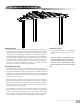
I n t r o d u c t i o n & O ve r v i e w (Alcove Pergola Shown) Getting Started First off, allow us to say thank you for the investment you have made in one of our fine pergola kits. This kit is designed to be assembled and installed ideally by two people with basic carpentry knowledge and tools. Do not attempt alone, especially during the installation stage.
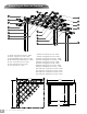
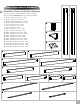
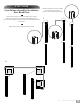
Alcove Pergola Materials Overview 1 7 16 4 2 17 18 8 19 10 3 12 14 15 6 13 11 5 9 1. 2. 3. 4. 5. 6. 7. Beams - Inner (2) 2” x 6” x 47 1/2” - 10234 Beams - Outer (2) 2” x 6” x 60” - 10235 Beam and Rafter Joiners (6) 2” x 6” - 10820 Decorative Pergola Ends (10) 2” x 6” - 10829 Post - Corner (1) 6” x 6” x 92” - 10236 Post - Ends (2) 6” x 6” x 92” - 10237 Post Caps (3) 6” x 6” - 10238 8. 9. 10. 11. 12. 13. 14. 15. 16. 17. 18. 19.
6 Alcove Pergola Materials Breakdown Check Boxes (Total of 5) for These Contents In the event of missing or defective parts please call our customer service dept. at 1 800 282 9346 (Mon. to Fri. 8:00 AM to 5:00 PM EST) 1. 2. 3. 4. 5. 6. 7. 8. 9. 10. 11. 12. 13. 14. 15. 16. 17. 18. 19.
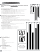
Pergola Additional Materials List Hardware (in plastic bag) A BCD E F NOTE: WE HAVE INCLUDED 10% EXTRA SCREWS BEYOND WHAT IS IDENTIFIED BELOW. All Screws Included with this Kit are Self-Auguring. A. Vinyl Weld Glue (2) - 20000 B. 1 1/2” Self-Auguring Stainless Steel Screws (14) - 20005 (to lock vinyl post and wood post together) C. 1 1/2” Self-Auguring Stainless Steel Screws (24) - 20005 (to lock Rafter and Beam Joiner) D.
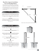
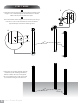
Wood Post Layout & Installation for In-Ground Application This pergola can also be installed on a pre-existing wood or concrete surface using our bolt down bracket system with a 4x4 wood post (sold separate). See page eight for more details. 1 Overhead View Post location and placement is the most critical step in the overall installation process. Please double check for the possibility of any underground utilities such as sprinkler, gas or telephone lines. 85 3/8 in 216.
OPTIONAL STEP Wood Post Layout & Installation Using Steel Post Base for Concrete or Wood Surface 1 Overhead View 1 89 in 226 cm Measure and mark out the location of the steel post bases using measurements shown aside. Note that measurements are center-to center. For dimensions between the wood posts, refer to the previous page. 2 89 in 226 cm Fasten the steel post bases to your concrete or wood surface and to the wooden posts according to the manufacturer’s instruction.
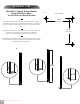
STEP THREE Vinyl Column Assembly & Installation Over Wood Posts *Ensure that holes at top of column are orientated correctly for future beam and rafter placement. 1 Slide the three posts over the wooden post as shown. Note the position and orientation of the different posts. The routed rectangular holes should all line up for future beams placement. 1 2 Adjust the post as per the illustration shown.
STEP THREE 3 3 Fasten the top of the vinyl post to the wooden post using a total of eight 1 1/2” screws through the pre-drilled holes as shown. Make sure the posts are 84 inches apart. 4 Fasten the bottom of the vinyl post to the wooden post using a total of six 1 1/2” screws as shown. The screws should be approximately 3 and 6 inches off the ground. 4 ±6 in ±3 in 84 in 213.4 cm 84 in 213.4 cm 84 in 213.4 cm 84 in 213.
STEP FOUR Beams Assembly 1 Insert an inner beam followed by a joiner and an outer beam as shown. Note the mitered end. 2 Insert a 2x6x8’ board into the beam. The joiner may need to be detached from the two beam sections to guide the board through. Board should be inserted up to the mitered end 3 Fastened the joiner through the beam pieces and wood insert using a total of 4 1 1/2” screws as shown. 4 Repeat for second beam.
STEP FIVE Beams Installation 1 With a helper, Insert the non-mitered end into the routed holes at one of the end posts as shown. Overshoot the post by a few inches to allow the mitered end to be inserted in the next step. 1 2 Slide the beam over and into the routed hole in the corner post as shown until it bottoms out inside the post. 3 Repeat for second post. 4 Fasten the beams to the posts using a total of sixteen 3” screws as shown.
STEP SIX Rafter #1 Assembly 1 Take one of the 2x6x12’ board and notch out the ends as shown. 2 Insert the board through a joiner followed by the #1 Left and #1 Right Rafters as shown. Note: the stickers indicating the rafters should meet inside the joiner. 3 Center the wood insert about the rafter and fasten the joiner with four 1 1/2” screws as shown.
STEP SEVEN Rafter #2 Assembly 1 Take the 2x6x10’ board and notch out the ends as shown. You may want to cut the 10’ board down to 116” first and then notch out two, 6” x 3” sections on the underside as shown. 2 Insert the board through a joiner followed by the #2 Left and #2 Right Rafters as shown. Note: the stickers indicating the rafters should meet inside the joiner. 3 Center the wood insert about the rafter and fasten the joiner with four 1 1/2” screws as shown.
STEP EIGHT Rafter #3 Assembly 1 Take one of the 2x6x12’ board and cut into 7’ and 5’ sections. The 7’ section will be used for this rafter, and the 5’ section will be used for the last rafter assembly. Notch out the ends as shown. 2 Insert the board through a joiner followed by the #3 Left and #3 Right Rafters as shown. Note: the stickers indicating the rafters should meet inside the joiner. 3 Center the wood insert about the rafter and fasten the joiner with four 1 1/2” screws as shown.
STEP NINE Rafter #4 Assembly 1 Take the 2x6x5’ section from the previous step and notch out the ends as shown. 16 2 Insert the board through a joiner followed by the #4 Left and #4 Right Rafters as shown. Note: the stickers indicating the rafters should meet inside the joiner. 3 Center the wood insert about the rafter and fasten the joiner with four 1 1/2” screws as shown.
STEP TEN Rafters Installation 1 With a helper, place the four rafters onto the beams as shown. 2 Fasten each end of the rafters to the beams through the predrilled holes with the 4” screws provided.
STEP ELEVEN Shade Slats Installation 1 With a helper, place the eight shade slats onto the rafters as shown. The shade slats should be 12 inches apart and overhang the front beam by 9 3/4 inches. 2 Fasten all the shade slats onto the rafters at each intersection using the 1 1/2” screws provided. A total of 26 screws will be used in this step.
S T E P T W E LV E Post Caps and Decorative End Caps Installation 1 1 Apply a small amount of glue on the inside perimeter of the decorative end caps as shown. 2 Insert decorative end caps onto the beam. Hold for 30 seconds to allow the glue to set and a few more minutes to cure. 3 Repeat for all decorative end caps. 4 Pressure fit the three post caps onto the posts. You may use any remaining glue, but is not necessary. 2 4 www.wearevita.