
Use and Care Manual


4
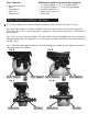
To remove the short inlet adapter use needle nose pliers. The adapter unscrews counter clock wise
(Fig. E). There is a gasket inside the inlet valve port (Fig F). Please do not remove the black gasket when
removing the short adapter and replacing it with the longer adapter (Fig. G). Tighten the longer adapter
clock wise with needle nose pliers (Fig. H).
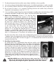
The bypass assembly is typically used to isolate
the control valve from the plumbing system’s water
pressure in order to perform control valve repairs
or maintenance. The ¾” full flow bypass valve
incorporates a service flow and bypass position.
The bypass assembly uses a piston type plunger
design to move from bypass to service flow. The
bypass position is used to turn off water flow to the
valve. The in service flow position delivers water
to the valve and tank to be softened and then
delivers soft water through the water plumbing in
the building.
Be sure to install the bypass assembly onto the main
control valve, before beginning plumbing or make
provisions in the plumbing system for a bypass.
The view of the bypass assembly (FIG. I) lists all the
components.
Fig. E - Short Inlet Adapter
Fig. H - Long Adapter installed
Fig. F - Short Adapter Removed
Fig. G - Long Adapter
CAUTION: Gasket
is in inlet valve port.
Do not remove gasket
from valve port when
removing the short
inlet adapter.
Bypass Assembly
Clips
2.
Fig. I