
User Manual


6
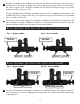
Theclipsconnectingthebypassassemblytothevalveareinsertedinthedownwarddirectionwhenthe
inletandoutletportsarefacingdownwards.Thelockingclipsareinsertedintheupwardsdirectionfrom
thebottomwhentheinletandoutletportsareupwards.
When the bypass assembly is in service mode the soft water is delivered to the building. During
regenerationcyclehardwaterisdeliveredtothewatersoftenerwhilealsoprovidinghardwatertothe
buildingdistributionsystem.
bypass assembly wiTh inleT and ouTleT
porTs faCing upwards)
bypass assembly wiTh inleT and ouTleT
porTs faCing downwards)
Locking Clips
insTallaTion insTruCTions
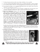
Assembling the Water Softener:
CAUTION: When maneuvering
the resin tank into the cabinet
do not attempt to lift the resin
tank by the top cover.
Rotate the valve and resin tank on the
ground to maneuver it into place for
the installation.
Fig. N Fig. O
Locking Clips
6.
7.
8.
Pleasecheckthattheflow
metercableisconnectedon
thevalveoutletport.