VT-EH Series 4, 8, and 16 Channel Digital Video Recorders VITEK • 4, 8, or 16 Video Inputs with 1 Main, 1 Spot Monitor Output and 1 DVI output • H.264 Compression • Supports both Dynamic and Static IP Addresses • 4, 8, and 16 Alarm Inputs / 1 Relay Out • Up to 120 IPS Recording (VT-EH4) / Up to 240 IPS Recording (VT-EH8 / VT-EH16) • Remote Viewing over the Internet, LAN, or Windows Mobile based PDA and iPhone.
1) Read these instructions. 2) Keep these instructions. 3) Heed all warnings. 4) Follow all instructions. 5) Do not use this apparatus near water. 6) Clean only with a dry cloth. 7) Do not block any of the ventilation openings. Install in accordance with the manufacturer's instructions. 8) Do not install near any heat sources such as radiators, heat registers, stoves, or other apparatus that produce heat. 9) Do not defeat the safety purpose of the polarized or grounding type plug.
● Installation should be carried out only by qualified personnel and in accordance with any electrical regulations in force at the time. ● The DVR must be placed on a stable surface or mounted in an approved cabinet. Adequate ventilation must be provided, taking particular care not to block any of the air vents on the DVR. ● Adequate protection against lightning strikes and power surges must be installed to prevent damage to the DVR.
MOUSE CONTROLL Designed to be controlled by mouse and easy to use. ENHANCED GRAPHICAL USER INTERFACE [GUI] The DVR menu structure and on screen display is presented in a simple to use and logical GUI format. GENUINE PENTAPLEX OPERATION The DVR will continue to record at full frame rate during local playback, local setup, multi user remote viewing and playback and remote setup. AUDIO 4 audio inputs are supported which can be assigned to any video channel.
TELEMETRY CONTROL Full telemetry control is available from the front panel or remote connection and a wide number of speed dome protocols are supported. Protocols can be set individually for each channel and telemetry speed can be adjusted to suit particular speed domes. EXTENSIVE MONITOR SUPPORT The DVR has 2 main monitor outputs (Composite and DVI) which can be used simultaneously. Support is also provided for 1 spot monitors and each spot monitor output can be programmed in the DVR setup.
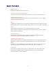
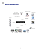
Remote PC (Client) Alarm Sensor Image Printer Alarm out Alarm Input/Out Camera NETWORK TCP/IP Video In AVI Backup DVR system WEB Client Backup Video Out Remote Controller VCR VGA Monitor AV Monitor 5 CD-RW USB
1. Front panel description.
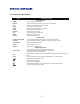
2. Rear panel description. A B C D E F G H A. CAMERA INPUT : Connect up to 16 camera inputs. B. MONITOR : Main BNC monitor. SPOT OUT : BNC Spot monitor. C. AUDIO INPUTS & OUTPUTS : Up to 4 audio inputs and one audio output can be connected as necessary. D. PAL / NTSC : Change Camera input type. E. ALARM INPUTS : Up to 4 alarm inputs can be connected and configured as high or low inputs with common ground.
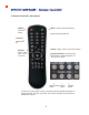
3. Remote Controller description. POWER MENU : Open System Setup Menu System O N/OFF Channel Selection Buttons ID Button Select DVR ID ID ENTER : Apply / Select /Go to Next Screen RETURN Cancel / Des elect Previo us Screen Navigation Buttons : Used for Play back Control, Menu Navigation, an d PTZ/Focus Control Change Display Search Mode Menu PTZ/IRIS Mode ※ If there are many DVRs on stack, each DVR must be set different ID then R emote controller set each ID on DVR.
• Connect up to 16 CAMERA INPUTS as necessary. • Connect one or more monitors to the DVR using the COMPOSITE or DVI connections • Connect power to the DVR. The DVR checks for proper power connection and emits two be eps. Press the POWER BUTTON on the front panel of the DVR to begin operation. The DVR startup screen detects and checks the status of hard drives and the CDRW / DVR-RW drive. After startup diagnostics are complete, the operator m ust logon to the system. The default user name is ‘ADMIN’ .
All menus can be controlled from above Status bar with mouse or front buttons. DIVISION SCREEN Select the ‘DISPLAY” button and screen division menu will be appeared. Select the screen type. (1,4,6,8,9,16 and rotation sequence)). Sequence mode User can select the type from display menu. Press the SEQ button. Each channel is shown in full screen for a set period of time before switching to the next channel. To stop the sequence on a particular channel, press the SEQ button again.
PTZ 1) CAM: Select the Channel 2) Sequence: If pressing the “START” button after assig ning the “Preset” in advance, sequence will be started. 3) Position name: Input the name after assigning the “P reset” location. 4) Avail. Position: User can see the available Preset loca tion. If clicking the “GOTO” button after selecting it, Ca mera will be moved. Press the “REMOVE” button to dele te the saved Preset location. 5) Zoom, Focus, IRIS: User can control the each item with +,- button.
LOG User can see the current log immediately. Click once after selecting log, recorded data will be played. This is in case of sele cting the “PREVIEW” option) Panic Recording This is menu to start and stop the Panic recording. If the panic recording is started, record icon will be changed as red square with “P”. Select to return once more. - Panic recording setup will be assigned from Record menu.
Quick Menu User can use quick menu by clicking the right of th e Mouse on each live cha nnel. Click the right of the Mouse on live channel that user wants to control. 1. Freeze On/Off: User can stop the live display of channel that user wants. Even th ough other channel show live display, this particular channel display is stopped. Cl ick to return once more. 2. PTZ : Please refer “PTZ” menu of Page 16. 3. Zoom : Please refer “ZOOM” menu of Page 16. 4.
In case of selecting “go to’” menu, thi s menu will be appeared. After selecting the time, press “OK”. 5. Record Start (Stop) Please refer “Panic record” menu of Page 17.
Click the “MENU” and click the SYSTEM SETUP menu. After Input the password (Default is 1234). Then main menu will appear. To navigate around any items in the setup menu, use the CURSOR KEYS and the ENTER and RETURN buttons. In general, the ENTER button is used to select and change a particular it em and the RETURN button is used to cancel a change or exit from a particular setup screen. To setup all main system functions, highlight SYSTEM SETUP and press ENTER.
CAMERA Click the CAMERA menu. CAMERA : CAMERA SETUP To setup the various camera options, highlight CAMERA and press ENTER. TITLE: Input the camera title. COVERT: When it is set to ON, the camera image is not displayed in live dis play but continues to be recorded. AUDIO: Determines the audio recording channel. CAMERA : COLOR SETUP Brightness, contrast, tint and color can be adjusted for each individual channel. Highlight which channel to modify and press ENTER.
Click the each value by . button The selected channel is displayed in full screen. BRIGHTNESS, CONTRAST, TINT and COLOUR can be changed as necessary. To modify a different channel, highlight CAMERA and choose the desired channel. Press RETURN when all changes are complete. CAMERA : PTZ SETUP Click the PTZ SETUP menu and click the each value on the ADDRESS, PROTOCOL and BAUD RATE menu. Change the value by button. ADDRESS: The unique ID of the PTZ device. PROTOCOL: The protocol of the PTZ device.
CAMERA : MOTION SENSOR Click the MOTION SENSOR menu an d click the value on the SENSITIVITY menu. Change the value by button. SENSITIVITY : Between 1 (Lowest) and 10 (Highest) and determines the degree of motion required before recording is activated. Click the button. AREA SETUP : Choosing this option allows the operator to define which areas of the image are monitored for motion detection.
DISPLAY : To setup the various display options, highlight DISPLAY and press ENTER. DISPLAY - OSD Click the OSD menu.. Then click the button for ON/OFF and change the value . STATUS BAR : Determines the time to turn from the menu of status bar to time display. CAMERA TITLE : Determines whether the camera title is displayed. RECORDIGN MODE ICON : Determines whether the DVR recording status is shown at the top right of each channel display window.
DISPLAY : MONITOR Click the MONITOR menu Then click the button for ON/OFF and change the valu e SEQUENCE DWELL : The time when each screen is displayed in a sequence op eration. SPOT DWELL : The time when each screen is displayed on the spot monitor o utputs. DE-INTERLACE MODE : When recording any channels in D1 resolution (704 x 576), this should be set to ON to prevent judder during playback. ALARM POP-UP MODE : When set to ON, an alarm input will cause the associ ated channel to display full screen.
DISPLAY : SEQUENCE Click the SEQUENCE menu . When the SEQ button is pressed, the default sequence will cycle through all 16 channels, one by one. Sequence setup allows the operator to define a custom sequence, using mix ed multi screen views and any desired channels. Click the ADD menu. To add a new sequence, highlight ADD and press ENTER. Sequence title is highlighted – press ENTER to bring up the virtual keybo ard and key in a name or reference number for the new sequence.
Press ADD. Then, “Sequence Setup” menu appear. Determine the “VIEW TYPE” and assign “CONFIGURE”. Then, click CONFIRM. To add the additional mode, click ADD continuously. After finishing the setup, press CLOSE. To modify the current one, double click that mode. Then ‘Sequence Setup” window will appear again. The new sequence is now saved and can be started by pressing the SEQ button when in live view.
DISPLAY : SPOT-OUT Click the SPOT-OUT menu and click the camera channel for ON/OFF. The DVR has 4 SPOT MONITOR OUTPUTS (Digital Spot). User can assign the SPOT OUT display each channel. Double click the spot out channel that requires to be assign. SPOT TITLE: input the title. ACTIVATION: Determines ON/OFF. Press MODIFY. (Below is default setup) To modify the current display, double click this display. Then ‘Spot Sequence Setup” window will appear. How to setup is same with Sequence setup.
SOUND Click the SOUND menu. To setup the various sound options, highlight SOUND and press ENTER SOUND : AUDIO Click the AUDIO menu and click the ON/OFF menu. Then, click the for ON/OFF. button LIVE AUDIO : When it is set to ON, the selected audio channel can be monitored on the AUDIO OUTPUT. AUDIO MONITORING CHANNEL : Specify which one of the 4 AUDIO INPUTS is routed to the AUDIO OUTPUT. NETWORK AUDIO TX : When set to ON, live and playback audio is transmitted to a remote PC connection.
SYSTEM Click the SYSTEM menu. To setup the various system options, highlight SYSTEM and press ENTER. SYSTEM : DATE / TIME Click the DATE / TIME menu. DATE TIME : Allows the operator to set or modify the current date & time. DATE FORMAT : Determines how the date is displayed. TIME FORMAT : Determines how the time is displayed. NETWORK TIME SERVER SETUP : If the DVR is connected to the Internet, the time and date can be accurately set by selecting SYNC and pressing ENTER.
SYSTEM : SYSTEM MANAGEMENT Click the SYSTEM MANAGEMENT men u. SYSTEM INFORMATION: User can see the system information as below. F/W version : Shows the firmware version of the DVR. H/W version : Shows the hardware version of the DVR. VIDEO SIGNAL TYPE : The DVR automatically switches between PAL and NTSC depending on the channel 1 input signal at power on.
SYSTEM NAME : It is used so that notification emails can be identified. F/W UPDATE : Firmware updates may be released periodically to enhance system performance and add extra features. The operator can upgrade the firmware using a USB memory stick. After inserting the F/W in USB or CD/DVD, Press UPDATE. Then , below menu will appear. After selecting the F/W from F/W list, press UPGRADE. Then, F/W upgrade is started.
USER Click the USER menu. To setup the various system options, highlight USER and press ENTER. USER: USER MANAGEMENT By default, the DVR is configured with a user ID of ADMIN, belonging to the ADMIN group and with a password of 1234. As well as the ability to add new users, existing user details can be modified. To modify user details, highlight the user with the green cursor and press ENTER. The user number that can create is Max. 8 users. For edit, double click on the each tap.
For ADD, double click on the each tap after clicking ADD. After changing, click OK. USER ID : Edit the user ID using the virtual keyboard. PASSWORD : Change the password using the virtual keyboard. GROUP : Users can belong to one of three groups - ADMIN, MANAGER or USER. E-MAIL : Enter the users email address if email notification is required. E-MAIL NOTIFICATION : Enable or disable email notifications for this particular user. USER: USER AUTHORITY User can give the authority to the MANAGER and USER.
NETWORK Click the NETWORK menu and determines each value. NETWORK: IP SETUP Click the IP SETUP menu. DHCP : When enabled, the DVR will obtain an IP address automatically if it is connected to a DHCP server or router. WEB SERVICE : When enabled, it allows remote connections using Internet Explorer or other web browsers. IP ADDRESS : If DHCP is not being used, the IP address can be manually set. GATEWAY : If DHCP is not being used, the gateway IP address can be manually set.
NETWORK: DDNS DDNS : When enabled, the DVR can be accessed through a Dynamic DNS server. Commonly used if a broadband connection does not have a static IP address. DDNS HOST NAME : User can enter any name to connect by web broswer. NETWORK: E-MAIL Click the E-MAIL menu. SERVER : The SMTP outbound email server that should be used to send email notifications. PORT : The outbound email port number. SECURITY : Set to OFF if the SERVER does not require a username and password to connect.
EVENT / SENSOR Click the EVENT / SENSOR menu. To setup the various event handling options, highlight EVENT/SENSOR and press ENTER. EVENT / SENSOR: HDD EVENT Click the HDD EVENT menu. The DVR can monitor the hard drives and detect problems that may be developing. SMART ALARM : Enables SMART disk monitoring. CHECK INTERVAL : Can be adjusted as desired. DISK FULL EVENT: Determines ON/OFF. EVENT / SENSOR : ALARM INPUT Click the ALARM INPUT menu an d click the OPERATION and TYPE value.
EVENT / SENSOR : ALARM OUTPUT Click the ALARM OUTPUT menu and click the each value. Determines the behavior and actions that will trigger each of the 8/16 alarm outputs. Behavior settings ALARM OUT : Choose which alarm output to configure. channel) OPERATION : The selected alarm output can be enabled or disabled. MODE : Can be either TRANSPARENT (the output is active only when the trigger criteria is present) or LATCHED (the output is active for a set period of time after a trigger).
EVENT / SENSOR : BUZZER OUT Click the BUZZER OUTPUT m enu and click the each value. Determines the behavior and actions that will trigger the internal buzzer. Behavior settings OPERATION : The internal buzzer can be enabled or disabled. HDD EVENT : Determines whether a hard drive event sounds the buzzer. MODE : Can be either TRANSPARENT (the buzzer sounds only when the trigger criteria is present) or LATCHED (the buzzer sounds for a set period of time after the trigger).
EVENT / SENSOR : EMAIL NOTIFICATION Click the EMAIL NOTIFICATION menu and click each value. Determines the behavior and actions that will send an email to a remote user. Behavior settings NOTIFICATION : Email notification can be turned ON or OFF. SETUP CHANGE: Determines whether a setup change sends an email. HDD EVENT : Determines whether a hard drive event sends an email. BOOTING EVENT: Determines whether a booting event sends an email.
DISK MANAGE Click the DISK MANAGEMENT menu. Then, click the PRESS menu for FW Upgrade, Factory Default and System Data. To manage the internal hard drives, highlight DISK MANAGE and press ENTER. RECORD TIME LIMIT : In certain circumstances, it may be necessary to limit the a mount of footage stored on the DVR (to comply with data protection laws for exam ple). Recording can be limited to 12 hours, 1 day, 2 days, 3 days, 1 week or one m onth.
RECORD MENU Click the “MENU”. Input the password . Then main menu will appear. Click the RECORD menu. To setup the recording behavior of the DVR, highlight RECORD MENU and press ENTER. RECORD : RECORDING OPERATIONS Click the RECORDING OPERATION menu and click each value. Then, click the value by to change. button SCHEDULE MODE : Either DAILY (one schedule will apply to every day of the week) or WEEKLY (each day of the week has its own schedule).
RECORD : CONTINUOUS/MOTION Click the CONTINUOUS/MOTION SET UP menu. This setup screen allows the operator to configure scheduled and motion detection recording. There are 2 sections: SIZE/FPS/QUALITY : Recording settings for each channel can be defined across a 24 hour period, in blocks (for example between 09:00 and 18:00) or for each individual hour. Note th at when SCHEDULE MODE is set to WEEKLY, each day of the week can also be selecte d.
Click the TIMEBAR that user wants. Press ENTER to display the green cursor. The green cursor shown represents one hour. The table below the time bar shows the recording settings for this time period. Drag the time that user wants. Example: To change the recording settings between 09:00 and 18:00. Use the CURSOR KEYS to move the green cursor to the 09:00 position and press ENTER. The cursor changes to orange to show the start position.
Click the SIZE, FPS, QUALITY and AUDIO value. Then click the value by change. button to Press ENTER. Recording settings for the selected time period are displayed. SIZE : Recording resolutions of 352x240, 704x240 or 704x480(NTSC) can be selected for each channel. FPS : Frame rates between 1 and 30 can be set for each channel. QUALITY : Four different picture recording qualities can be set for each channel. AUDIO : If audio devices are connected to the DVR, user can select the audio recording on/off.
ACTIVATION Click the ACTIVATION menu. To change ACTIVATION settings, highlight CONTINUOUS/MOTION SETUP and press ENTER. Use the CURSOR KEYS to highlight ACTIVAITION and press ENTER. The schedule box is highlighted in green. Drag the Time and Channel by left mouse. After selecting the area, determines the recording type. The schedule screen has 4 symbols to show the different recording modes. RED blocks: No scheduled or motion recording. SKY BLUE blocks: The DVR will record continuously.
RECORD : ALARM SETUP Click the ALARM SETUP menu. The setting is same as CONTIN UOUS/MOTION SETUP. This setup screen allows the operator to configure alarm input activated recording. SIZE/FPS/QUALITY : Recording settings for each channel can be defined across a 24 hour period, in blocks (for example between 09:00 and 18:00) or for each individual hour. Note that when SCHEDULE MODE is set to WEEKLY, each day of the week can also be selected.
RECORD : PANIC SETUP Click the PANIC SETUP menu. Select the Size, Frame, Quality and audio. During panic recording mode, the DVR will override all other recording settings and record continuously on all channels at the settings configured here.
SEARCH To search for a particular section of recorded footage, press the SEARCH button. To protect unauthorized viewing of footage, only ADMIN and MANAGER user levels can playback footage. To login as ADMIN, enter the default password of 1234 and press ENTER. SEARCH : TIME SEARCH Click the date that user wants. The DVR uses a calendar and timeline search method for quick access to recorded footage. The calendar displayed on the left shows the current month.
Drag the time bar by left mouse. Press ENTER to select the calendar and use the CURSOR KEYS to move to the required day. As different days are selected, the timeline display also changes to show recorded footage on that day. Press ENTER to choose the day and move to the timeline. Click the PLAY menu. Use the CURSOR KEYS to move the timeline cursor left or right to select the time segment required. The currently selected time is displayed above the calendar.
The default playback mode is 16 screen display. By pressing DISPLAY or using the CHANNEL SELECTION buttons, it is possible to display single screen or other multi screen formats in a similar way to the live display mode. During playback, turning the SHUT TLE WHEEL steadily clockwise increases the playback speed by up to 64 times. Turning steadily anticlockwise will reverse play by up to 64 times. When the SHUTTLE WHEEL is released, playback is paused.
SEARCH MODE : PANORAMA Search Click the PANO button . PANO( Thumb nail) : Each Screen show s 3 hour data.
During playback, user can reserve the recording data that want to archive. Press button at the time the archive was started. Then playback is stopped and below menu will appear. After inputting “TAG” name, press START. Then display is returned to playback. Press button at the time that end to archive again. Then below menu will appear again. RESERVE: Press this to reserve current data. CONTINUE: Press this to reserve the data more. Then display will be return to playback.
SEARCH : EVENT SEARCH The DVR event log stores events such as motion and alarm activated recording, video loss etc. To search for an event and playback the recorded footage, press the SEARCH button and log in as ADMIN with the default password of 1234. Click the SEARCH BY EVENT menu and each value. Then click the value by button to change. Click the SEARCH menu. Playback resumes from the moment when the selected event occurred and continues until stoppe d by the operator.
NEW ARCHIVING To archive recorded footage to USB memory stick or CD/DVD, press the ARCHIVE button. To protect unauthorized viewing and distribution of footage, only the ADMIN user level can archive footage. To login as ADMIN, enter the default password of 1234 and press ENTER. Click the each value. Then, click the value by change. button to Click the QUERY menu. Make sure to press QUERY first before selecting BURN or RESERVE. Press RELEASE to reset after QUERY.
RESERVED DATA MANAGEMENT AVI ARCHICING LIST: User can see the AVI archiving data that reserved from new archiving menu or archiving of search. INFORMATION: The detailed information of Reserved AVI data. DELETE: User can delete the reserved AVI data BURN: Backup the selected AVI data. SNAPSHOT ARCHICING LIST: User can see the snapshot archiving data. INFORMATION: The detailed information of Reserved snapshot data. DELETE: User can delete the reserved snapshot data BURN: Backup the selected snapshot data.
• WEB Connection Setup For using web connection, 554 and 8080 ports should be port forwarding in Router. ♣ How to Connect Input the IP Address or URL of the DVR in the Internet Explorer Address Bar. If user uses the DDNS, input the URL as below. http://1234.dvrlink.net Enter DVR User name an password.
• Click the following ActiveX control and install.
• LIVE Mode • Explanation of function button in LIVE mode Select live division screen. Move to next screen and make full screen. Select live channel. Save the live image. Print the current screen. Snapshot the current screen.
• Status : Can see the current DVR status. • Log : Can see the log. • PTZ : Can control connected PTZ camera.
•SEARCH Mode • Search by time 1. Refresh : Refresh the data. 2. Play : After select the date and time, can play the data. 3. Backup : Can backup special channel and time.
• Search by event 1. Event : Select necessary event to playback. 2. Period : Select the date an time of Start to End. 3. Search : Start the selected data.
• SETUP Mode All settings are same as DVR setup. Refer to Page 20.
• INFORMATION Check DVR model name and WEB version.
28492 Constellation Road Valencia, ca 91355 WWW.VITEKCCTV.