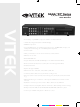
SAGA “ST” Series 4, 8, and 16 Channel Digital Video Recorders VITEK • The Industry’s only MPEG4 Compression with Non-Conditional Refresh • 120 IPS Recording and Real-Time 480 IPS Display • MPEG-4 Compression • Up to 42 HDD support: 1.
SAGA “ST” Series PACKAGE CONTENTS Prior to installation of the SAGA series DVR, please verify that the packaging contains the following contents: 1. 2. 3. 4. 5. 6. 7. 8. One SAGA “ST” series DVR One AC Adaptor One Power Cable One Remote Controller DVR Viewer Program CD This Instruction Manual. Two AAA batteries. Rack Mount Ears and screws. If any of the contents are missing, please contact the Vitek Customer Help Desk immediately.
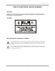
SAGA “ST” Series RISK OF ELECTRICAL SHOCK WARNING WARNING TO REDUCE THE RISK OF FIRE OR ELECTRIC SHOCK, DO NOT EXPOSE THIS PRODUCT TO RAIN OR MOISTURE. DO NOT INSERT ANY METALLIC OBJECTS THROUGH THE VENTILATION GRILLS OR OTHER OPENINGS ON THE EQUIPMENT.
SAGA “ST” Series DISCLAIMER While every effort has been made to ensure that the information contained in this guide is accurate and complete, no liability can be accepted for any errors or omissions. Vitek Industrial Video Products, Inc. reserves the right to change the specifications of the hardware and software described herein at any time without prior notice.
SAGA “ST” Series FCC NOTICE Saga Series Digital Video Recorders, VT-ST420, VT-ST820, VT-ST1620 These devices comply with Part 15 of the FCC Rules. Operation is subject to the following two conditions; 1. These devices may not cause harmful interference, and 2. These devices must accept any interference received, including interference that may cause undesired operation.
SAGA “ST” Series Read this First Test Sessions Before you try to record important subjects, we highly recommend that you make several test sessions to ensure that the Digital Video Recorder is operating and being operated correctly. Please note that Vitek Industrial Video Products, Inc., its subsidiaries and affiliates, and its distributors are not liable for any consequential damages arising from any malfunction of the Digital Video Recorder or its accessories. The Privacy act of 1974 (5 U.S.C.
SAGA “ST” Series SAFETY PRECAUTIONS Before using the Digital Video Recorder, please ensure that you read and understand the safety precautions described below. Always ensure that the Digital Video Recorder is operated correctly. The safety precautions noted on the following pages are intended to instruct you in the safe and correct operation of the Digital Video Recorder and its accessories to prevent injuries or damage to the self, other persons and equipment.
SAGA “ST” Series Do not allow the equipment to come into contact with, or become immersed in, water or other liquids. Do not allow liquids to enter the interior. The Digital Video Recorder has not been waterproofed. If the exterior comes into contact with liquids or salt air, wipe it dry with a soft, absorbent cloth. In the event that the water or other foreign substances enter the interior, immediately turn the Digital Video Recorder’s Power off or unplug the power cord from the power outlet.
SAGA “ST” Series PREVENTING MALFUNCTION Avoid Strong Magnetic Fields. Never place the Digital Video Recorder in close proximity to electric motors or other equipment generating strong electromagnetic fields. Exposure to strong magnetic fields may cause malfunctions or corrupt image data. Avoid Condensation Related Problems. Moving the equipment rapidly between hot and cold temperatures may cause condensation (water droplets) to form on its external and internal surfaces.
SAGA “ST” Series TABLE OF CONTENTS PACKAGE CONTENTS............................................................................................ 1 RISK OF ELECTRICAL SHOCK WARNING ............................................................ 2 DISCLAIMER ............................................................................................................ 3 FCC NOTICE ............................................................................................................ 4 Read this First..........
SAGA “ST” Series 4.4 FREEZE............................................................................................................ 36 4.4.1 SINGLE SCREEN VIEW MODE.............................................................. 37 4.4.2 MULTI SCREEN VIEW MODE ................................................................ 37 4.5 ZOOM ............................................................................................................... 38 4.6 PICTURE-IN-PICTURE..................................
SAGA “ST” Series 6.1.5 PRE-RECORD TIME ............................................................................... 77 6.1.6 POST-RECORD TIME............................................................................. 78 6.1.7 IMAGE QUALITY..................................................................................... 78 6.1.8 AUDIO RECORD..................................................................................... 78 6.1.9 REMOTE CONTROL ID ...............................................
SAGA “ST” Series 6.5.7.3 User Authority............................................................................... 109 6.5.7.4 DVR Menu Setup ......................................................................... 109 6.5.7.4.1 Menu Initialize ........................................................................... 109 6.5.7.4.2 Load menu from file................................................................... 110 6.5.7.4.3 Save menu to file.....................................................
SAGA “ST” Series 10.6.3.1 Record........................................................................................ 161 10.6.3.2 Record Program ......................................................................... 161 10.6.3.3 Holiday ....................................................................................... 162 10.6.4 EVENT................................................................................................. 162 10.6.4.1 Event ..............................................
SAGA “ST” Series I. FEATURE HIGHLIGHTS 1.1 OPERATION A. PENTAPLEX PLUS FUNCTION Simultaneous record, playback, mirror, backup, network transmission and partial live view. B. REAL-TIME DISPLAY Each channel is displayed at 30pps during live monitoring. C. DIGITAL ZOOM Up to 2 times digital zoom display. D. PICTURE-IN-PICTURE E. EASY OPERATION Control through the front panel buttons, IR remote controller, external joystick keyboard controller and USB 2.0 compliant mouse. F.
SAGA “ST” Series 1.3 PLAYBACK A. MULTI-SCREEN Single, quad, 6, 7, 9, 10, 13 and 16 channel playback. B. VERSATILE SEARCH OPTIONS Calendar, search & copy, timeline, event, block, file and bookmark search. C. PREVIEW Snapshot of search date and time in search mode. 1.4 NETWORK A. MULTI-SITE LIVE MONITORING Monitor up to 16 DVRs, or up to 256 cameras simultaneously. B. REMOTE PLAYBACK Review recorded data from the client software with fast forward and rewind, slow and pause. C.
SAGA “ST” Series 1.6 STORAGE A. GENEROUS STORAGE CAPACITY Two available internal hard drive bays allow up to 1.5 terabyte of storage and optional removable hard drive bay allows an additional 750 gigabytes of storage, for a maximum of 2.25 terabyes of storage. B. HARD DRIVE EXPANSION BAY (VT-XHD10U) Up to four VT-XHD10U hard drive expansion bays can be connected to the DVR. Each expansion bay is capable of supporting up to ten hard drives, totaling 30 terabytes of additional storage. C.
SAGA “ST” Series II. SAGA “ST” SERIES DIGITAL VIDEO RECORDER LAYOUT 2.1 FRONT PANEL LAYOUT 1 11 12 2 3 13 14 4 5 6 7 8 16 18 20 22 15 17 19 21 9 10 23 24 25 1. AUDIO SELECT This button selects the recorded audio channel when in multiple display mode. Press the button repeatedly to toggle between audio channels 1 through 4. 2. NUMERIC BUTTONS / CHANNEL SELECT a) Selects a specific channel number to be displayed in full screen. b) Enter the numeric password when prompted. 3.
SAGA “ST” Series 8. PLAY / PAUSE / ZOOM OUT a) Starts the playback of recorded data. By default, the playback starts from the earliest recording. If the recording has been played back, the playback will start from where it was left off. b) Toggles between playback and pause mode. c) Zoom out in PTZ mode. 9. FAST / FORWARD PICTURE BY PICTURE a) Fast forward. Press this button repeatedly to toggle between 2X normal playback speed through 128X normal playback speed.
SAGA “ST” Series 16. PIP / LOOP PLAYBACK CLEAR / DOWN DIRECTIONAL BUTTON a) Activates the picture-in-picture mode. b) Tilts down in PTZ mode. c) Navigates left in the menu screen. d) Moves the zoom box left in zoom mode. e) Clears the loop playback in playback mode. 17. DIGITAL ZOOM / RIGHT DIRECTIONAL BUTTON a) Enters digital zoom mode. b) Pans right in PTZ mode. c) Navigates right in the menu screen. d) Moves the zoom box right in zoom mode. 18.
SAGA “ST” Series 2.
SAGA “ST” Series 1. CAMERA INPUT BNC connectors for composite video signal input. 2. SPOT OUTPUT Spot monitor BNC connector for composite video signal output. 3. RJ-45 ETHERNET PORT 10/100Base-T RJ-45 port for network connection. 4. RS-232C Reserved. The RS-232C port can be used to connect a variety of devices to control the DVR. 5. AUDIO OUTPUT RCA connector for audio signal output. 6. AUDIO INPUT 1 / 2 1/8” Jack connector for audio channels 1 and 2 input. 7.
SAGA “ST” Series 15. RELAY OUT Terminal blocks for relay out 1 through 4. 16. TIME SYNCHRONIZATION Input and Output terminal blocks for time synchronization between DVRs. 17. ALARM INPUT Alarm input 1 through 4 on VT-ST420, 1 through 8 on VT-ST820 and 1 through 16 on VT-ST1620. 18. POWER IN DC power socket for 12VDC 6.67 Amps.
SAGA “ST” Series 2.3 IR REMOTE CONTROLLER 1 2 3 5 4 7 6 9 8 11 13 10 12 14 15 17 16 19 18 20 22 21 23 24 25 1. REMOTE CONTROLLER ID Select the remote controller ID. 2. IRIS CONTROL 3. ZOOM CONTROL 4. SPOT MONITOR / ESC 5.
SAGA “ST” Series 6. ALARM RESET / LEFT DIRECTIONAL BUTTON 7. MENU / UP DIRECTIONAL BUTTON 8. PIP / DOWN DIRECTIONAL BUTTON 9. DIGITAL ZOOM / RIGHT DIRECTIONAL BUTTON 10. AUTOMATIC SEQUENCE / FOCUS OUT / DECREASE VALUE 11. FREEZE / FOCUS IN / INCREASE VALUE 12. SEARCH / PRESET 13. COPY / AUTOFOCUS 14. PTZ / BOOKMARK 15. SLOW 16. PLAY / PAUSE 17. FAST 18. LIVE 19. DIRECTION 20. RECORD 21. MULTI (DISPLAY) 22. TEXT 23. AUDIO SELECT 24. NUMERIC BUTTONS / CHANNEL SELECT 25.
SAGA “ST” Series 2.4 MOUSE CONTROL 1 2 3 1. LEFT MOUSE BUTTON a) Double-click in the main window: status display. b) Double-click in the menu screen: select item or icon. 2. SCROLL WHEEL Scroll up or down to change the value of the selected item. 3. RIGHT MOUSE BUTTON a) Single-click in the main window: enter main menu. b) Double-click in the menu screen: exit to main screen.
SAGA “ST” Series III. INSTALLATION AND CONNECTIONS 3.
SAGA “ST” Series 3.
SAGA “ST” Series 3.3 EXTERNAL TERMINAL CONNECTION 3.3.1 RS-485 No DESCRIPTION 1 TA(TX+) RS485:Transmit data 2 TB(TX-) RS485: Receive data 3 GND 3.3.
SAGA “ST” Series 3.3.3 RELAY OUTPUT NO DESCRIPTION NO DESCRIPTION 1 NO(Normal Open) 7 NO(Normal Open) 2 CM(Common) 8 CM(Common) 3 NC(Normal Close) 9 NC(Normal Close) 4 NO(Normal Open) 10 NO(Normal Open) 5 CM(Common) 6 NC(Normal Close) ALARM V-LOSS 11 CM(Common) 12 NC(Normal Close) 3.3.
SAGA “ST” Series 3.3.5 VGA PIN LAYOUT No DESCRIPTION 1 RED(Red Video [75ohm, 0.7Vp-p] ) 2 GREEN(Green Video [75ohm, 0.7Vp-p] ) 3 BLUE(Blue Video [75ohm, 0.7Vp-p] ) 4~12 Reserved 13 HSYNC or CSYNC(Horizontal or Composite Sync.) 14 VSYNC(Vertical Sync.) 15 Reserved 3.3.
SAGA “ST” Series IV. BASIC OPERATION This section will cover basic features of the DVR, including its main screen and the explanation of some of the alerts. It will also cover the DVR status, the view modes of the DVR, automatic sequence, digital zoom, basic playback modes and audio playback. 4.1 MAIN SCREEN 1 2 3 4 1. REMAINING HARD DRIVE SPACE / PLAYBACK STATUS The remaining hard drive space is displayed either in percentage or in Gigabytes.
SAGA “ST” Series 3. DATE AND TIME Current date and time is displayed when in live monitoring mode. Recorded date and time is displayed when in playback mode. 4. CHANNEL INFORMATION The channel information is displayed. When the channel is in normal recording mode, it will display the channel title as entered by the user. When the channel is in event recording mode, it will display the appropriate event recording mode: alarm, motion and video loss. 4.
SAGA “ST” Series 5. RECORD PROGRAM Displays current recording program. 6. RECORD TYPE Displays current event recording mode. 7. SOFTWARE VERSION Displays current software version of the DVR. 8. HARDWARE VERSION Displays current hardware version of the DVR. 9. DHCP (DYNAMIC HOST CONFIGURATION PROTOCOL) Displays the status of the DHCP application. 10. IP ADDRESS Displays currently assigned IP address. 11. SUBNET MASK Displays currently assigned subnet mask. 12. GATEWAY Displays currently assigned gateway.
SAGA “ST” Series 4.3 LIVE VIEW The live view displays each channel at 30 frames per second, for the total of 120 frames per second for VT-ST420, 240 frames per second for VT-ST820 and 480 frames per second for VT-ST1620. 4.3.1 LIVE VIEW MODE SEQUENCE Press the DISPLAY button to toggle between different view modes. 4.3.1.
SAGA “ST” Series 4.3.1.2 VT-ST820 8 Channel Mode A 7 Channel Mode 6 Channel Mode 4 Channel Mode A 4 Channel Mode B 4 Channel Mode C 4 Channel Mode D 4 Channel Mode E 4.3.2 FULL SCREEN DISPLAY Press the desired channel button to directly display the channel on the monitor. Press +10 then a secondary number for any channel numbers higher than 9. Press Numeric button 1 to display channel 1.
SAGA “ST” Series Press +10 button and then 2 button to display channel 12. 4.3.3 AUTOMATIC SEQUENCE Press the SEQ button to activate the automatic sequence display. Please change “ADD AUTO SINGLE” option to ON to include single channel display into the automatic sequence. Any of the view modes can be skipped by selecting the dwell time to 0. … 16 Channel Mode … 10 Channel Mode … 4 Channel Mode A 7 Channel Mode … Channel 1 Channel 16 4.
SAGA “ST” Series 4.4.1 SINGLE SCREEN VIEW MODE In single screen view mode, press the FREEZE button to freeze the live screen. As the screen freezes, “FREEZE” will be displayed in the upper left corner of the screen. Press the FREEZE button once more to unfreeze the screen. 4.4.2 MULTI SCREEN VIEW MODE In any multi screen view mode, press the FREEZE button and “FREEZE” will be displayed in the upper left corner of the screen. Please note that none of the channels will be frozen immediately.
SAGA “ST” Series 4.5 ZOOM During the live view mode or during the playback mode, it is possible to zoom into a section of the screen to get a digital close-up of up to 8 times the normal size. Press the numeric button to select the channel to zoom into. Press the ZOOM button to enter the zoom mode. The initial zoom ratio is 2X the normal size. Use the directional buttons to move the zoom window to the desired location. Press the ESC button to exit out of the zoom mode.
SAGA “ST” Series 4.6 PICTURE-IN-PICTURE Select the background channel by pressing the desired numeric button. Press the PIP button to activate the PIP mode. Pressing the numeric buttons will change the PIP window to change the channel to the desired channel. Use the directional buttons to place the PIP window to the desired location on the screen. Press the ESC button to exit from the PIP mode.
SAGA “ST” Series 4.7 SPOT MONITOR The spot monitor allows viewing of individual cameras in live mode while the main monitor may be busy with different tasks, such as playback. The ST series offers a single channel spot output. During any view modes, press the SPOT button for Spot Monitor Mode. Press any channel numbers to display the channel in full screen mode on the spot monitor. The spot monitor will display the channel accordingly. Press the SPOT button to exit from the Spot Monitor Mode.
SAGA “ST” Series 4.8 BASIC RECORDING When the REC button is pressed, the SAGA series DVR uses Program 6, which is the default record setting: There are total of 10 customizable record programs. Please note that QUICK SETUP supersedes any other recording settings when activated.
SAGA “ST” Series 4.9 BASIC PLAYBACK 4.9.1 PLAY / REVERSE PLAY / PAUSE / STOP Press the PLAY / PAUSE button and the play icon will be displayed. The DVR starts the playback from the earliest recorded data if the playback mode is entered for the first time. Press the DIRECTION button to change the playback direction. Press the PLAY / PAUSE button during the playback to pause the playback. When the playback reaches the end of the recorded data, then the playback will pause automatically.
SAGA “ST” Series 4.9.2 FAST FORWARD / REWIND The FAST button accelerates the speed of playback in one direction. Each pressing of the button accelerates the speed twice the previous speed. In other words, from normal speed, the acceleration increment is 2X, 4X, 8X, 16X, 32X, 64X and 128X. Pressing the DIRECTION button will change the direction of fast forward to rewind while maintaining the same speed. 4.9.3 PICTURE-BY-PICTURE Pause the playback by pressing the PLAY / PAUSE button.
SAGA “ST” Series 4.9.4 SLOW The SLOW button slows down the speed of playback in one direction. Each pressing of the button further slows down the speed twice the previous speed. In other words, from normal speed, the slow down increment is 1/2X, 1/4X, 1/8X, 1/16X, 1/32X, 1/64X and 1/128X. Pressing the DIRECTION button will change the direction of slow playback to the opposite direction while maintaining the same speed. 4.9.
SAGA “ST” Series As soon as the end of the loop is marked, then the playback returns to POSITION A. When the end the loop is reached, the playback returns to POSITION A and the loop playback is repeated. Press the CLEAR button to exit from the loop playback mode. 4.9.6 BOOKMARK The bookmark provides a quick and easy way to mark the desired location during playback so that it can be easily retrieved for later playback.
SAGA “ST” Series 4.9.7 AUDIO PLAYBACK The audio is always recorded in real time regardless of the recording speed. To listen into the desired audio channel, press the AUDIO SEL button and then channel 1 through 4. By default, the audio will playback along with the equivalent video camera (i.e. channel 1 audio will play back along with channel 1 video).
SAGA “ST” Series V. ADVANCED OPERATION This section will cover advanced features of the DVR such as backup (copy), pan tilt and zoom camera controls, alarm, video loss and motion recording, and various playback search options. 5.1 BACKUP The DVR is capable of backing up to various media, such as DVD-RW, CD-RW, USB Flash drives, and external hard drives. Please note that besides the optical media, the backup devices must be USB 2.
SAGA “ST” Series Select INTERNAL CD-RW/DVD by pressing the + or = buttons. Highlight MEDIA FORMAT, and then press the ENTER button to begin formatting. FORMATTING will be displayed during the process. The process may take up to approximately 20 minutes depending on the format of the backup disk. When the process is completed, SUCCESS will be displayed. Press the ESC button to return to the previous menu. Highlight COPY and then press the ENTER button to access the copy submenu.
SAGA “ST” Series Select the location of the file to be backed up from. If the location is unknown, leave the HDD ID on NORMAL. Select the channels to be backed up. By default, all channels are selected. To exclude a channel, highlight a channel number and then switch them to “--“. The beginning and the end of the available files are listed automatically as shown on the left. Select the beginning time and the end time of the period to be backed up, and then press the ENTER button to start the backup.
SAGA “ST” Series The backup progress is displayed on the right upper corner of the screen, and will disappear automatically when the backup process is finished. The backup disk can be reformatted and reused over and over. Insert the CD into the CD-ROM or DVD-ROM of a computer, and the small player will load automatically showing all available data for playback. 5.1.2 CD-R Highlight COPY and then press the ENTER button to access the copy submenu. Select INTERNAL CD-RW/DVD by pressing the + or – button.
SAGA “ST” Series The beginning and the end of the available files are listed automatically as shown on the left. Select the beginning time and the end time of the period to be backed up, and then press the ENTER button to start the backup. When prompted, enter an eight digit numeric password to encrypt the backup. This password will be needed to later retrieve the data. Data encryption can be bypassed by pressing the ESC button. The DVR will start creating a buffer for the selected data to be backed up.
SAGA “ST” Series Insert the CD into the CD-ROM or DVD-ROM of a computer, and the small player will load automatically showing all available data for playback. 5.1.3 USB FLASH MEMORY The USB 2.0 flash memory comes in various sizes, up to 8 Gigabytes of storage per flash memory. It is much faster in comparison to optical media when it comes to copying necessary files. The following manufacturers’ models have been tested to be fully compatible with the SAGA series DVRs.
SAGA “ST” Series Select the location of the file to be backed up from. If the location is unknown, leave the HDD ID on NORMAL. Select the channels to be backed up. By default, all channels are selected. To exclude a channel, highlight a channel number and then switch them to “--“. The beginning and the end of available file are listed automatically as shown on the left. Select the beginning time and the end time of the period to be backed up, and then press the ENTER button to start the backup.
SAGA “ST” Series The backup progress is displayed on the right upper corner of the screen, and will disappear automatically when the backup process is finished. The copied files are listed as “Dvr-20060503202016.dvr”. They can be retrieved and played back using the client software, or the embedded program – “FileViewer.exe”. 5.1.4 EXTERNAL HARD DISK DRIVE Follow the same procedure as the USB flash memory in section 5.1.2. 5.1.
SAGA “ST” Series Displays the current copy status. 5.1.6 COPY STOP The backup process can be interrupted at any time during the process. Press the COPY button to enter the COPY submenu. Highlight COPY and then press the ENTER button to access the copy submenu. Instead of the normal copy submenu, the DVR will display an option to stop the backup process.
SAGA “ST” Series Highlight YES and then press the ENTER button to stop the backup process. 5.2 PAN / TILT / ZOOM CAMERA CONTROL The SAGA series DVR comes with an extensive list of compatible PTZ cameras. Please read and follow the PTZ manufacturer’s instruction manual and understand its settings fully prior to proceeding to attempt to connect and control the PTZ camera through the DVR. Please refer to PTZ model selection under 6.6.5 PTZ under 6.6 LINK SETUP on page 118. 5.2.
SAGA “ST” Series 5.2.2 CREATING AND MOVING TO PRESET POINTS During the PTZ control mode, press the PRESET button to activate the PTZ(PRESET)MOVE mode. If there are any preset points predefined, pressing the numeric buttons will move the PTZ camera to the preset points. A total of 16 preset points can be recalled. If there are no preset points predefined, then press the PRESET button once again to activate PTZ(PRESET)SET mode.
SAGA “ST” Series notification e-mails if the e-mail addresses have been defined. Please see 6.4.8 RELAY OUTPUT under 6.4 EVENT SETUP section on page 101 and 6.6.5 E-MAIL under 6.5 LINK SETUP on page 119. 5.3.1 ALARM RECORDING Alarm recording is a form of event recording that triggers off of the circuit lines connected to the terminal blocks in the rear of the DVR. Typical circuits comprise of normally closed circuits (NC) and normally open circuits (NO).
SAGA “ST” Series 5.3.3 MOTION RECORDING Motion recording is yet another effective form of event recording that is triggered when a channel detects motion in its field of view. The channels which detect motion will display the “MOTION” message. The REC button will light up and the channel status will change the color to red in the channels in which the motion was detected. The recording will include the pre and post recording time on the channels that are recording. 5.
SAGA “ST” Series The dates that contain recorded data will be displayed in clear font, whereas dates without data will be in white. Select the desired date and then press the ENTER button. To change the month or the year, highlight the month or the year and then adjust the value by pressing the + and – buttons. When a date is selected, the DVR will then search again for the recorded data in a 24-hour period for the date. The hour blocks that contain data will be displayed in yellow.
SAGA “ST” Series 5.4.2 SEARCH & COPY Search & copy allows a quick review of the recorded data and backup onto a medium, and thus minimizes the need to navigate through different screens to pinpoint the exact time and duration of the video. Press the SEARCH button to access the search screen. Highlight SEARCH & COPY and then press the ENTER button to access the SEARCH & COPY screen. Select which hard disk drive to retrieve the data from. If unknown, leave the HDD ID to “NORMAL”.
SAGA “ST” Series If any of the channels need to be viewed in full screen mode, highlight CHANNEL and then press the + or – button to view a specific channel. Press the ENTER button and the playback will begin. Maneuver through the playback as needed. Please see BASIC PLAYBACK on page 42. When the desired footage has been found, press ESC to return to SEARCH & COPY screen.
SAGA “ST” Series When the password has been entered, “SAVE NEW COPY PASSWORD” will appear. The same message appears even if the ESC button has been pressed. The backup process will begin and the progress will be displayed in the upper right hand corner of the screen. 5.4.3 TIME SEARCH Time search provides an overview of the recorded data from the earliest available recording to the latest available recording. Press the SEARCH button to access the search screen.
SAGA “ST” Series Select which hard disk drive to retrieve the data from. If unknown, leave the HDD ID on “NORMAL”. Select the year, month, date, hour, minutes and seconds of the beginning of the data to retrieve. As the values change, the picture in the preview window will change accordingly. If any of the channels need to be viewed in full screen mode, highlight CHANNEL and then press the + or – button to view a specific channel. Press the ENTER button and the playback will begin.
SAGA “ST” Series Press the SEARCH button to access the search screen. Highlight EVENT SEARCH and then press the ENTER button to access the EVENT SEARCH screen. Select which hard disk drive to retrieve the data from. If unknown, leave the HDD ID on “NORMAL”. if any of the channels need to be viewed in full screen mode, highlight CHANNEL and then press the + or – button to view a specific channel. Select the event type by pressing the + and – button.
SAGA “ST” Series Select the year, month, date, hour, minutes and seconds of the end of the data to retrieve. As the values change, the picture in the preview window will change accordingly. If all events need to be searched up to the present time, leave the time as is. Press the ENTER button and the list of events will appear in chronological order, from the most recent to the oldest. Select the event and then press the ENTER button to start the playback.
SAGA “ST” Series Highlight BLOCK SEARCH and then press the ENTER button to access the BLOCK SEARCH screen. Select the hard disk drive to retrieve the data from. If unknown, leave the HDD ID on NORMAL. Select the year, month, date, hour, minutes and seconds of the end of the data to be retrieved. Press the ENTER button and the list of data will appear in chronological order, from the most recent to the oldest. The data is associated with the logical block address of the hard disk drives.
SAGA “ST” Series Maneuver through the playback as needed. Please see BASIC PLAYBACK on page 42. 5.4.6 FILE SEARCH File search is capable of reading and playing back the data from the media used for backup. Insert the CD-RW or the DVD-RW into the DVD tray or connect the USB flash memory or the external hard disk drive into the USB port. Press the SEARCH button to access the search screen. Highlight FILE SEARCH and then press the ENTER button to access the FILE SEARCH screen.
SAGA “ST” Series Press the ENTER button and the list of data will appear in chronological order, from the oldest to the most recent. Select the data and then press the ENTER button to start the playback. Maneuver through the playback as needed. Please see BASIC PLAYBACK on page 42. 5.4.7 BOOKMARK SEARCH Bookmark search looks up any bookmarks that have been added by the user. Please see 4.8.6 BOOKMARK under 4.8 BASIC PLAYBACK on page 45. Press the SEARCH button to access the search screen.
SAGA “ST” Series Press the ENTER button to search for the list of bookmarks. Select the bookmark, and then press the ENTER button to start the playback. Maneuver through the playback as needed. Please see BASIC PLAYBACK on page 42. 5.4.8 TEXT SEARCH Text search allows searching for Point Of Sales interface entries to bring up the specific time related to a transaction. Press the SEARCH button to access the search screen.
SAGA “ST” Series Highlight TEXT SEARCH and then press the ENTER button to access Text Search submenu. Select the hard disk drive to retrieve the data from. If unknown, leave the HDD ID on NORMAL. Select the channel in which to search for the text string. Select the year, month, date, hour, minutes and seconds of the end of the search time. Highlight TEXT and then press the ENTER button to enter the text string to search.
SAGA “ST” Series Enter the text to be searched. Leave black for a wild card (all item) search. Move the highlight to any location besides TEXT, and then press the enter button to list the results. Highlight an entry, and then press the ENTER button to start playback. Maneuver through the playback as needed. Please see BASIC PLAYBACK on page 42. 5.4.9 LOG FILE SEARCH The log file keeps a list of the important events that happened to the DVR.
SAGA “ST” Series z z z z z z z Power on / off Power loss / DVR restart Changes in the menu DVR initialization HDD initialization Network connection / disconnection Record start / stop Press the SEARCH button to access the search screen. Highlight LOG FILE SEARCH and then press the ENTER button to access the LOG FILE list. Select the year, month, date, hour, minutes and seconds of the end of the log list to retrieve.
SAGA “ST” Series Press the ESC button and highlight SAVE LOG and then press the ENTER button to save the log file onto a USB flash memory. The USB flash memory must be in the front USB port. The log file will be saved as “DvrLog.log” file. Double-click the left mouse button to open and view the log file.
SAGA “ST” Series VI. DVR MENU Press the MENU button to access the main menu of the DVR.
SAGA “ST” Series 6.1 QUICK SETUP Quick setup enables the user to quickly setup major recording settings of the DVR. All changes made in quick setup are affected equally to all channels. This includes the image size, record speed, image quality, event options, pre and post recording time and audio record settings. Moreover, the activation of quick setup overrides any other recording settings as the quick setup supersedes regular record setup. 6.1.
SAGA “ST” Series 6.1.3 RECORD FRAME Record frame determines the overall recording speed of the DVR. The recording speed adjusts automatically according to the image size and divided equally between all available channels. As an example, the 60 available recording speed is divided equally between 16 channels on the VT-ST1620. The default is 60 PPS. The following chart shows the maximum recording speed for each resolution.
SAGA “ST” Series 6.1.6 POST-RECORD TIME Define the post-event recording time. Select from 0 to 60 seconds. The default is ten seconds. 6.1.7 IMAGE QUALITY Define the recording image quality. Available options are LOW, FINE and SUPERFINE. The default is SUPERFINE. 6.1.8 AUDIO RECORD Select the audio recording on or off for all eight channels. The default is OFF. 6.1.9 REMOTE CONTROL ID Select the identification number of the DVR. There are a total of 16 available numbers to choose from.
SAGA “ST” Series For more information regarding the REMOTE CONTROL ID, please see 6.5.6 REMOTE CONTROLLER ID under SYSTEM menu on page 107. The default is ALL. 6.2 SCREEN SETUP ` Screen setup defines various screen related options. Any changes affect the main video as well as the spot monitor output of the DVR. 6.2.1 AUTO SEQUENCE Highlight AUTO SEQUENCE and then press the ENTER button to access four pages of the auto sequence submenu.
SAGA “ST” Series The second page lists the sequence display duration for the nine channel display mode A and B, ten channel display mode, 13 channel display mode, 16 channel display mode, and the option to include single channels. Select the inclusion of single channels in the automatic sequence. The default is off. The third page lists the sequence display duration for channels 1 through 8.
SAGA “ST” Series 6.2.2 DISPLAY Highlight DISPLAY and then press the ENTER button to access the display submenu. Select the display option for the remaining space on the hard disk drive. The default is on. Select the display mode for the remaining free space on the hard disk drive. The default is in percentage. Select the display option for the recording status. The default is on. Select the display option for the date and the time. The default is on.
SAGA “ST” Series Select the date format. The default is DD/MM/YY. Select the display option for the channel title. The default is on. Select the display mode for the channel title. The default is in text mode. The bitmap mode title can only be edited using the client software. Select the border color that divides the channels. The default is white. Select the display option for the remote controller ID. The default is OFF.
SAGA “ST” Series 6.2.3 TITLE Highlight TITLE and then press the ENTER button to access the title submenu. Press the enter button to edit the channel title. Navigate through the characters by using the directional buttons, and advance through the characters using the + or – buttons. Press the ENTER button to select the characters. Up to eight characters can be entered for the channel title. 6.2.4 MULTI-SCREEN Several multi-screen viewing modes can be customized using any combination of cameras.
SAGA “ST” Series Select a view mode to customize. The view mode can be disabled to be removed from the sequence of view modes. The default is on. Highlight the channel to customize, and then press the + or – button to select the desired channel. 6.2.5 COVERT Highlight COVERT and then press the ENTER button to access the covert channel submenu. The first page lists the covert mode options for channels 1 through 8. Highlight the desired channel and press the + or – button to activate the covert mode.
SAGA “ST” Series The second page lists the covert mode options for channels 9 through 16. Highlight the desired channel and press the + or – button to activate the covert mode. Select the covert mode application. By default, the live view, playback and network are affected by the covert mode. Available options are: z z z z z z z LIVE ONLY PLAYBACK ONLY NETWORK ONLY LIVE AND PLAYBACK LIVE AND NETWORK PLAYBACK AND NETWORK ALL Select the display of covert on or off.
SAGA “ST” Series Select the spot monitor display mode: z z z Manual Event Sequenced The default is manual. Define the spot monitor sequence mode time from 1 to 60 seconds. The default is 3 seconds. The channels without video signals can be skipped. Select on or off. The default is on. 6.2.7 CAMERA Highlight CAMERA and then press the ENTER button to access camera adjustment submenu. Select the channel which needs to be adjusted.
SAGA “ST” Series Adjust the brightness. The default is 50%. Adjust the contrast. The default is 50%. Adjust the hue. The default is 50%. Adjust the saturation of the color. The default is 50%.
SAGA “ST” Series 6.3 RECORD Record setup defines various recording options such as record schedule, record programs, recording time estimate, audio recording, repeat recording, play modes, backup mode and holiday recording schedules. 6.3.1 RECORD SETUP There are 10 customizable Record Programs arranged in hourly blocks that can be individually scheduled and adjusted. Scheduling allows the DVR to record at specific times even when the REC button is not on.
SAGA “ST” Series 1 2 3 4 1. All Select the program for the whole day by changing the value in this section. 2. Current hour block Highlights the current program for the current time. 3. Schedule recording Displays the hour blocks with schedule recording. Schedule recording forces the DVR to record even when the REC button is off. 4. Daily overview Displays the recording program for each hour block of the day. Each hour block can be programmed with different recording programs.
SAGA “ST” Series Any of the record settings can be customized once in the record program mode. Any changes made will be effective only to the hour block. 6.3.2 RECORD PROGRAM Highlight RECORD PROGRAM and then press the ENTER button to access the record program submenu. 1 2 3 4 5 6 7 8 1. RECORD PROGRAM There are 10 available record programs, from program 0 through program 9, where program 0 reflects the QUICK SETUP settings. Each program can be customized and executed from RECORD SETUP.
SAGA “ST” Series 2. EVENT RECORD SETTING The DVR offers two distinctive methods for recording events: SINGLE mode versus COMPLEX mode. Furthermore, both modes offer EVENT CHANNEL only and ALL CHANNELS mode for a total of four possible event recording options. A. Single Mode Single Mode event recording allows recording a specific channel at up to 30 pictures per second regardless of the image size.
SAGA “ST” Series When the REC button is on, this setup continuously takes one picture per second until a movement is detected, where the record rate will jump to 15 PPS for the channel that triggered the event. Please note that the total of the Single Mode event recording rate of 240 PPS exceeds the maximum D1 resolution record rate of 30 PPS, but in reality, a total of 30 PPS is used per group at any given moment.
SAGA “ST” Series The illustration shows that at any given time, a channel would record at 30 PPS when an alarm circuit is triggered, whereas the rest of the channels will record at 2 PPS ( (60 – 30) / 15 = 1 PPS). For example, if channel 3 is triggered to start recording at 30 PPS, channels 1, 2 and 4 through 16 start recording at 2 PPS. B. Complex Mode Complex Mode event recording records exactly at the predetermined record rate for all channels.
SAGA “ST” Series 6.3.3 IMAGE QUALITY Image quality predicts how much time the DVR will record based on the record settings. Highlight IMAGE QUALITY and then press the ENTER button to access the image quality screen. Select the image quality by pressing the + or – button. The FILE SIZE, RECORD TIME and TOTAL TIME will adjust automatically based on the picture quality and the content of the camera. Please verify that the REC button is off. 6.3.
SAGA “ST” Series 6.3.5 REPEAT RECORD Highlight REPEAT RECORD and then press the ENTER button to access the audio record submenu. Select the repeat recording option on or off. The default is on. Select the threshold at which the alarm will sound. Select from 5% to 10%, or off. The default is 5%. 6.3.6 PLAY MODE Select the playback mode for the recorded data.
SAGA “ST” Series 6.3.7 BACKUP MODE Select the recording mode for the backup hard disk drives. Available options are: z z MIRROR: create a real-time duplicate copy of the normal recording hard disk drives. EVENT: create a backup hard disk drive of event recordings only. The default is off. 6.3.8 HOLIDAY Highlight HOLIDAY and then press the ENTER button to access the holiday schedule screen. Select the holiday recording option on or off. The default is off. Define the holidays in MM/DD format.
SAGA “ST” Series 6.4 EVENT Event setup defines various event options such as the motion grid and the motion detection sensitivity, the main screen event response option, buzzer option, sensor input and relay output options. 6.4.1 MOTION DETECTION Highlight MOTION DETECTION and then press the ENTER button to access the motion detection submenu. Select the channel to customize motion related options by pressing the + or – buttons.
SAGA “ST” Series Adjust the sensitivity of the motion detection from 1 to 5 by pressing the + or – buttons. The default is 5. Highlight AREA SETUP and then press the ENTER button to access the motion grid setup screen. Move the grey cursor around using the directional buttons, and then press the ENTER button to disable each grid. Press the ESC button to return to motion menu. z z No tint: motion detection on Green tint: motion detection off The default is on for all grids.
SAGA “ST” Series 6.4.2 EVENT SCREEN MODE Define how the main video output reacts when an event occurs. SCREEN HOLD: maintains the current view mode. z EVENT FULL: the channel in which the event occurs is displayed in full screen. z EVENT MULTI: regardless of which channel the event occurs in, the view mode is changed into multiple channel view mode. EVENT F RTN: when an event occurs, the view mode is changed to that of the channel with the event, and then returns to the previous view mode.
SAGA “ST” Series 6.4.5 EVENT MESSAGE RESET Select the duration of the event message to be displayed from 1 to 30 seconds. The default is 5 seconds. 6.4.6 EVENT BUZZER Select the buzzer option on or off. The default is off. 6.4.7 SENSOR INPUT Highlight SENSOR INPUT and then press the ENTER button to access the sensor input submenu. Select the sensor input type, or the type of the circuit to be used with each channel. Available options are, normally closed (NC), normally open (NO) and not used.
SAGA “ST” Series 6.4.8 RELAY OUTPUT Highlight RELAY OUTPUT and then press the ENTER button to access the relay output submenu. The first page lists relay output options for channels 1 through 8. For each channel, it is possible to customize relay 1 through 3 for each of the event options. To change the relay output for each event, highlight the relay output and then press + or – buttons to change to the desired output number. The second page lists relay output options for channels 9 through 16.
SAGA “ST” Series 6.5 SYSTEM System setup defines various system settings such as hard disk drive settings, system clock, password for multiple users, video standard, language, remote controller, and the key echo. Moreover the system settings can be reinitialized, saved or retrieved from the USB flash memory, as well as updating the DVR firmware. 6.5.1 HARD DISK DRIVE Highlight HDD and then press the ENTER button to access the hard disk drive management submenu. 6.5.1.
SAGA “ST” Series The DVR detects installed hard disk drives automatically. Any hard disk drive can be defined to be a normal recording drive (REC drive) or a backup drive (BACKUP). Highlight a desired drive and then select the function for the hard disk drive by pressing the + or – button. Highlight EXTERNAL, and then press the ENTER button to access the list of hard disk drives in the expansion bay, VT-XHD-10U. The hard disk drives will be automatically detected just as in the main DVR HDD bays.
SAGA “ST” Series 6.5.1.3 Backup HDD initialize The backup hard disk drives can be initialized at any time by accessing this menu. Highlight BACKUP HDD INITIALIZE and then press the ENTER button to access the initialization screen. Select YES and then press the ENTER button to initialize the hard disk drives. Initialization is instantaneous. Select NO to return to the previous menu screen. 6.5.2 CLOCK Highlight CLOCK and then press the ENTER button to access the system clock submenu. 6.5.2.
SAGA “ST” Series Advance through the year, month, date and time by using the directional buttons, and use the + or – button to adjust the values. Once the value has been adjusted, press the ENTER button to make the new date and time effective. Press ESC to return to the previous menu. 6.5.2.2 Time Adjust Highlight TIME ADJUST and then press the ENTER button to access time adjust submenu. Select automatic time adjustment through internet time server on or off. The default is off.
SAGA “ST” Series Select the time zone for the local time. For the list of the time zone for your local area, please see Appendix I on page 175. Select the DAYLIGHT SAVINGS TIME option on or off. The default is off. Define the daylight savings time starting month, week, day and time. Define the daylight savings time ending month, week, day and time. 6.5.3 VIDEO STANDARD Select the video standard by pressing the + or – buttons. Available standards are NTSC, PAL, and AUTO.
SAGA “ST” Series 6.5.4 LANGUAGE Select from seven available language settings: z z z z z z z English Korean Japanese Polish Spanish Russian Chinese 6.5.5 REMOTE CONTROL ID If there is more than one DVR present at the same location and each DVR needs to be controlled separately using a remote controller, then each DVR can be addressed differently so that all of them can be controlled using one remote controller.
SAGA “ST” Series 6.5.7 ADVANCED SETUP The DVR’s passwords and different access levels can be configured from the Advanced Menu, as well as saving and retrieving the DVR menu settings. 6.5.7.1 Password Check Select password check option on or off.
SAGA “ST” Series Enter eight numbers for the new password, and then re-enter the same password under RE-TYPE section. The asterisks will advance automatically as the numbers are entered. 6.5.7.3 User Authority Highlight USER AUTHORITY and then press the ENTER button to access user authority screen. Highlight and modify each user’s level of authority by pressing the + or – buttons. 6.5.7.
SAGA “ST” Series Select YES and then press the ENTER button to reset back to factory default. Select NO to exit without resetting. 6.5.7.4.2 Load menu from file Highlight LOAD MENU FROM FILE and then press the ENTER button to load a DVR setting from the USB flash memory. The USB flash memory with the DVR menu file must be inserted into the front USB port. The DVR will attempt to read from the USB flash memory.
SAGA “ST” Series When saving the DVR menu settings is successful, the DVR will display “ENV COPY SUCCESS”. 6.5.9 FIRMWARE UPGRADE The DVR’s software can be upgraded for the latest feature updates, fixes and improvements via the USB flash memory. Highlight FIRMWARE UPGRADE and then press the ENTER button to access the firmware upgrade screen. Select YES and then press the ENTER button to begin the firmware upgrade. The USB flash memory with the upgrade file must be inserted into the front USB port.
SAGA “ST” Series Once the file is found, it will check for the integrity of the file. If the integrity of the file is intact, then it will start the upgrade process. The upgrade progress will be shown in percentages. The whole process should take approximately two minutes. Do not remove the USB flash memory from the USB port during the upgrade. When the upgrade is finished, the DVR will display “COMPLETED! RESTART DVR”. Power off and power on the DVR to apply the upgrade.
SAGA “ST” Series 6.6 LINK Link setup defines various settings between the DVR and various devices such as internet connection, keyboard controllers, PTZ cameras and e-mails. 6.6.1 NETWORK Highlight NETWORK and then press the ENTER button to access the network setup submenu. Select DHCP option on or off. DHCP (Dynamic Host Configuration Protocol) is another word for Dynamic IP. If enabled, the DVR will obtain an IP address automatically from a router or from the Internet Service Provider.
SAGA “ST” Series Define the IP address if the DHCP is set to off. The DVR should be provided with its own static IP address. Define the subnet mask. The subnet mask should also be provided along with the IP address. Define the gateway. The gateway should also be provided along with the IP address and the subnet mask. Define the DNS (Domain Name Server).
SAGA “ST” Series Define the primary dynamic IP server’s address if a proprietary server is to be setup and used in conjunction with the DVR. Vitek provides a dynamic IP server to find the DVR even if it is connected on a dynamic IP service. Define the secondary dynamic IP server’s address if a proprietary server is to be setup and used in conjunction with the DVR. Select the network transmission method. z STILL: send still pictures. z MOTION: send conditionally refreshed pictures. The default is STILL.
SAGA “ST” Series Select the communication speed. Available speeds are from 1200 to 115200. The default speed is 115200. Select the data bit. Available options are 6 to 8. The default bit is 8. Select the parity bit. Available options are ODD, EVEN and NONE. The default is NONE. Select the stop bit. Available options are 1 and 2. The default is 1. 6.6.3 RS-485 Highlight RS485 and then press the ENTER button to access the RS-485 submenu.
SAGA “ST” Series Select the DVR’s system ID between 0 to 255. The system ID should be issued when controlling multiple DVRs with a keyboard controller such as VT-KBD1. The address should also be issued when controlling PTZ cameras from the DVR. The default ID is 1. Select the communication speed. Available speeds are from 1200 to 115200. The default speed is 9600. Select the data bit. Available options are 6 to 8. The default bit is 8. Select the parity bit. Available options are ODD, EVEN and NONE.
SAGA “ST” Series 6.6.4 PTZ The DVR can control as many Pan / Tilt / Zoom cameras as many as the number of channels it records on. As there are multiple vendors of PTZ cameras, the DVR also supports a variety of protocols.
SAGA “ST” Series Select the communication speed. Available speeds are from 1200 to 115200. The default is 9600. Select and match the PTZ camera address. For example, if the PTZ camera is set to address 2, then the ID should be set to 2. 6.6.5 E-MAIL The DVR is capable of sending e-mails when an event occurs to up to ten different email addresses. Highlight E-MAIL and then press the ENTER button to access the e-mail submenu.
SAGA “ST” Series 6.6.5.2 SMTP server Highlight SMTP SERVER and then press the ENTER button to define an e-mail server. Enter the e-mail server’s address. For example: mail.domainname.com Press the ESC button to return to previous menu. 6.6.5.3 DVR e-mail address Highlight DVR E-MAIL ADDRESS and then press the ENTER button to define the DVR’s e-mail address.
SAGA “ST” Series 6.6.5.4 User ID Highlight USER ID and then press the ENTER button to define the user ID for the DVR’s e-mail account. Enter the user name to log into the DVR’s e-mail account. Press the ESC button to return to previous menu. 6.6.5.5 Password Highlight PASSWORD and then press the ENTER button to define the password for the DVR’s e-mail address. Enter the password to log into the DVR’s e-mail account. Press the ESC button to return to previous menu.
SAGA “ST” Series 6.6.5.6 E-mail address 1 through 10 Highlight a desired e-mail address to send the notifications to, and then press the ENTER button to define the e-mail address. Enter the e-mail address. Press the ESC button to return to the previous menu.
SAGA “ST” Series VII. SEARCH Please see 5.4 ADVANCED PLAYBACK under section V. ADVANCED OPERATION on page 59. VIII. COPY Please see 5.1 BACKUP under section V. ADVANCED OPERATION on page 47.
SAGA “ST” Series IX. EXIT Any and all settings must be saved in order to be put into effect. After any setting has been modified, the ESC button can be pressed several times until the EXIT screen is shown. 9.1 SAVE ONLY SAVE ONLY will be automatically highlighted when the ESC button is pressed. Press the ENTER button to save the settings and to return to any other menus for further modifications. 9.
SAGA “ST” Series 9.3 EXIT WITHOUT SAVE Highlight and press the ENTER button to disregard any changes and exit to the live screen view mode.
SAGA “ST” Series X. CLIENT PROGRAM: DVR VIEWER The DVR Viewer is a dedicated client program that connects to, monitors and manages up to 16 DVRs simultaneously. 10.1 SYSTEM REQUIREMENT The DVR Viewer receives, decodes and displays data for up to 16 DVRs or up to 256 cameras simultaneously requiring a powerful personal computer to take full advantage of the program. The following is the minimum and recommended PC specification.
SAGA “ST” Series Click on NEXT. The DVR viewer will be installed in its default folder of C:\Program Files\DVR\DVR-Viewer. If the folder needs to be changed, click on “BROWSE…” button and then select a different folder. The setup program will run through its series of installation process. Click on FINISH to complete the installation.
SAGA “ST” Series 10.3 DVR VIEWER - LAYOUT Locate the DvrViewer icon on the desktop and double-click on it to run the client software. The program can also be located in START- Programs – DVR-Viewer. When the DVR Viewer is run for the first time, it prompts for the administrator’s password. Select and enter a password of up to 20 alphanumeric characters. Click on OK to start the program. The DVR Viewer has two display modes.
SAGA “ST” Series 1. DVR LIST The DVR List adds or removes individual DVRs and offers a variety of connection options. a b c e d f g h i j k l m n a. DVR List The DVRs that have been added are listed in this box. b. Connection Type Select the connection type to the DVR. c. DVR Name Enter the DVR name. d. IP Address and Port Enter the IP address and the port number for the DVR, if known.
SAGA “ST” Series e. Use IP Server The DVR can be located on the internet using the MAC address displayed in the status screen. If the MAC address is to be used, “Use IP Server” box must be checked. f. Domain Name / Use DDNS The DVR can be located on the internet using a domain name, or a web address. The DVR must be registered with a Dynamic DNS service in order to be located. If the Domain Name is to be used, “Use DDNS” box must be checked. g.
SAGA “ST” Series 2. DVR SEARCH Within a local area network environment (LAN), it is possible to automatically scan and list available DVRs to be added to the DVR list. Click on DVR SEARCH to open the DVR Search window. Click on SEARCH, and available DVRs will be listed. Highlight a desired DVR to add to the DVR List, and then click on ADD TO LIST. “DVR List Added.” Message will appear with a successful addition to the DVR list. Click on CANCEL to exit from DVR Search.
SAGA “ST” Series 3. HDD SEARCH The hard disk drive from the DVR can be directly connected to a PC, where the files can be searched and played back through the DVR Viewer. Click on HDD SEARCH to open the HDD Search window Select a hard disk drive, and then click on OK. Recorded channels will be shown in the main channel display window.
SAGA “ST” Series If the desired file is not listed in the current folder, then select the folder in which the files are saved by clicking on FOLDER SELECT. Select a file to view, and then click on PLAY to begin the playback. The file can also be played back by doubleclicking on it. Once the playback starts, it can be slowed, paused and fast forwarded using the playback buttons. The playback list can be viewed and selected again from the TIME search button once the playback starts. 5.
SAGA “ST” Series 5 ~ 9 DVRS 10 ~ 16 DVRS 6. VIEWER OPTION Viewer option defines the administrative options for the DVR Viewer, such as display options and the IP address of the Dynamic IP Server, and user management to create user name and passwords for additional users to access the DVR Viewer. A.
SAGA “ST” Series a. Display Check or uncheck various On Screen Display options as needed. By default, Channel Title, Event and Frame Rate are checked. b. Dynamic IP Server Modify the IP address for the Dynamic IP Servers as needed. The default IP addresses are: z z Primary Server: 211.174.251.155 Secondary Server: 211.174.251.160 c. Warning Sound Toggle event notification warning sound on or off. The default is on. d. Play Mode Field vs. Frame mode. e.
SAGA “ST” Series Modify the administrator’s description and passwords as needed. Up to 20 alphanumeric characters can be entered for the password. Press CHANGE to save the modification. To add additional users, click on ADD. Enter the user name, description for the user, password and access privileges, and then click on SAVE to add the new user. The user setting can be modified by highlighting the user and clicking on CHANGE once the changes are made.
SAGA “ST” Series 7. CHANNEL DISPLAY WINDOW Live or playback video from the DVR is transmitted and displayed up to 16 channels. Each channel displays information regarding the specific channel according to the settings in VIEWER OPTION. 8. DVR CLOSE The connected DVR can be disconnected by clicking on this button. 9. ATTACH / DETACH WINDOW The channel display window can be attached or detached to the controls by clicking on this button. 10.
SAGA “ST” Series identical to the front buttons of the SAGA “ST” series DVR. For more information on button functions, please see 2.1 FRONT PANEL LAYOUT under II. SAGA “ST” SERIES DIGITAL VIDEO RECORDER LAYOUT on page 17. 16. PTZ CONTROLLER e a b f g c d Pan, Tilt and Zoom cameras can be controlled remotely through the DVR Viewer. a. Channel select Select the channel in which the PTZ camera is installed. b. Directional buttons / Autofocus Move the PTZ camera using the directional buttons.
SAGA “ST” Series 18. STATUS Displays the current DVR status on System, Record and Network. 18.
SAGA “ST” Series 19. PRINT In live or playback mode, select any of the channels and then click on PRINT to bring up the screen print window. a b c d e f g h i a. Zoom in / out Click the + or – button to zoom in and out for the detailed view of the picture. b. Paper size Select the paper size. Available paper sizes are A3, A4, A5, B4, B5, Legal and Letter. c. Print Send the picture to the printer. d. Printer Select a printer to send the picture. e.
SAGA “ST” Series 20. COPY The data on the DVR can be downloaded onto the PC using the COPY function. The data can also be backed up directly onto available backup media on the DVR. a b c d e f g h i j k a. Available data Displays available data to be downloaded. b. Hard disk drive selection Select the hard disk drive to download from. If unknown, leave the selection on NORMAL. c. Copy time Define the interval of the file to be downloaded. Available time interval is 1 through 60 minutes.
SAGA “ST” Series h. DVR media Select the media on which the DVR will utilize for backup. All three USB ports and the internal DVD burner can be selected. i. Copy Click on copy after all parameters for downloading. j. DVR copy After selecting the media to be backed up on the DVR, click on DVR COPY to begin the backup process on the DVR. k. Cancel Exit from the COPY window. 21.
SAGA “ST” Series a b c d e a. Log list window List of DVR logs from the most recent to the oldest. b. Search Click on search to view available log list. c. Search time Select the year, month, date, hour, minutes and seconds of the end of the log list to retrieve. d. Save log Save the log list onto the computer. e. Cancel Exit from the log search window. 29. RECORD / PLAYBACK BUTTONS The remote playback can be controlled just as on the DVR.
SAGA “ST” Series b. Rewind This button can be toggled for rewind speed of 2x, 4x, 8x, 16x, 32x, 64x and 128x. c. Reverse slow This button can be toggled for a slow reverse playback speed of 1/2x, 1/4x, 1/8x, 1/16x, 1/32x, 1/64x and 1/128x. d. Reverse play Normal speed playback in reverse direction. e. Pause Pause the playback during remote playback or live monitoring. f. Play Normal speed playback in forward direction. g.
SAGA “ST” Series 34. LIVE / PLAYBACK BUTTON STATUS During live or playback, this window will display the direction and the speed of the playback direction. 35. RELAY 4 Manually trigger relay 4 on the DVR. The relay 4 option must be set to user option. 36. AVAILABLE SPACE ON COMPUTER When connected to a DVR, this section will display available recording space on the computer. 37. ACTIVE DVR / FILE / HDD Displays a list of connective DVRs, playback from FILE SEARCH and HDD SEARCH.
SAGA “ST” Series 10.4 DVR VIEWER - LIVE MODE Click on the DVR LIST, highlight a desired DVR and then click on CONNECT. a b c d e f g a. DVR’s local time Displays the DVR’s local date and time b. Event message Displays the channel’s event messages, alarm and motion.
SAGA “ST” Series c. Channel window The DVR channel window can be double-clicked for a full screen mode. The channel window can also be zoomed by dragging the left mouse button over the channel window. The size of the box created by dragging will be the outline of the channel window to be zoomed in. d. DVR functions Some of the DVR functions may not be available depending on what user account the DVR Viewer has been signed on with, and also with what user level password the DVR has been connected to. e.
SAGA “ST” Series 10.5 DVR VIEWER – PLAYBACK MODE Any DVRs that are connected online can be accessed to do data search remotely from the DVR and then transmit to the DVR viewer for remote playback. a b c d e f g a. DVR’s playback time Displays the DVR’s playback date and time. Channels without recording show NO IMAGE. b. Event message Displays the channel’s event messages at the time of the recording. c. Channel window The DVR channel window can be double-clicked for a full screen mode.
SAGA “ST” Series d. DVR functions Some of the DVR functions may not be available depending on what user account the DVR Viewer has been signed on with, and also with what user level password the DVR has been connected to. e. DVRs online The live view of different DVRs can be selected, as well as the playback mode, by clicking on the desired DVR name. f. Remaining HDD space Displays remaining hard disk drive space on the DVR. g. Channel status Displays the status of the live channels. 10.5.
SAGA “ST” Series Select the channel for playback. Select the year, month, day and time for the playback, or slide the time bar to the desired time. Click on PLAY to begin the remote playback. 10.5.2 CALENDAR SEARCH Click on CALENDAR to display the Calendar Search window. Dates with recorded data will be highlighted in yellow. Select the year, month, date, and the hour block, and then click on PLAY to begin the remote playback.
SAGA “ST” Series 10.5.3 EVENT Click on EVENT to display the Event Search window. The first 500 events are listed chronologically, from the most recent to the oldest. Select an event and then click on PLAY to begin remote playback. If the desired event is not listed in the current window, then follow the following steps. Select the hard disk drive for the remote playback. If unknown, leave the selection to Normal. Select the channel for playback. Select the event categories.
SAGA “ST” Series Select the year, month, day and time for the end of the event list for playback. The list can be advanced to the next 500 lists by clicking on NEXT. Highlight the desired event and then click on PLAY to begin the remote playback. 10.5.4 TEXT Click on TEXT to display Text Search window. Select the hard disk drive for the remote playback. If unknown, leave the selection to Normal.
SAGA “ST” Series Select the channel for the text string search. Enter the text string to search. Leave blank for a wild card (all items) search. Select the year, month, day and time for the end of the search time. Click on SEARCH to list data that match the text string. If the text string search was left blank, then it will display all items. Click on NEXT for the next 500 listing.
SAGA “ST” Series Highlight a text string, and then click on PLAY to begin the remote playback. The listing can be saved as a List file format. 10.5.5 BLOCK Click on BLOCK to display the Logical Block Address Search window. The first 500 data is displayed in chronological order, from the most recent to the oldest. Select the hard disk drive for the remote playback. If unknown, leave the selection to Normal.
SAGA “ST” Series Select the year, month, day and time for the end of the data. If the desired date and time is not found, then click on NEXT to display the next 500 Logical Block Addresses. Highlight a desired block time and then click on PLAY to begin the remote playback.
SAGA “ST” Series 10.6 DVR PLAYER – SETUP The DVR Viewer can change the settings on the DVR remotely. The features and settings are identical to that of the DVR menu. For more information, please see V. DVR MENU on page 75. Click on SETUP and the password prompt will be displayed. Enter the administrator’s password and then click on OK to display the DVR setup menu. 1 8 2 3 9 4 5 10 1. QUICK SETUP 2. SCREEN SETUP 3. RECORD SETUP 4.
SAGA “ST” Series 5. SYSTEM SETUP 6. LINK 7. DOWNLOAD Update the DVR’s firmware using the download menu. 8. READ FROM FILE Load DVR settings from a DVR setup file. 9. SAVE TO FILE Save DVR settings to a DVR setup file. 10. LOAD FROM DVR Load current DVR settings. 11. UPDATE TO DVR Upload changed settings to DVR. 12. CLOSE Close DVR Setup menu. 10.6.1 QUICK SETUP a. Quick Setup: on / off. b. Image Size: 360 x 240 / 720 x 240 / 720 x 480. c. Record Frame: 16 through 480, depending on image size. d.
SAGA “ST” Series 10.6.2 SCREEN 10.6.2.1 Auto Sequence a. Auto-Single: select the single channel dwell time. b. Auto-Split: select the multi channel dwell time. c. Video Loss Skip: check / uncheck. d. Add Auto Single: check / uncheck. 10.6.2.2 Display a. b. c. d. e. HDD Free Space: on / off. HDD Free Space Mode: percent / gigabyte. Record Status: on / off. Clock Display: on / off. Date & Time Mode: YY/MM/DD, MM/DD/YY, DD/MM/YY. f. Title Display: on / off. g. Title Mode: text / bitmap. h.
SAGA “ST” Series 10.6.2.4 Title a b d f c e g a. Channel Title (text mode) Enter up to eight alphanumeric characters for channel titles. b. Clear Clear the bitmap drawing. c. Move Move the bitmap drawing in the grids. d. Font Select the font for bitmap conversion. e. Download Download the bitmap to the DVR. f. Make Bitmap Enter the title to be converted into bitmap. g. Bitmap Grid The title can be drawn here.
SAGA “ST” Series 10.6.2.5 Multiscreen Customize the channels to be displayed in 4E, 6, 7, 9B, 10 and 13 channel view modes. 10.6.2.6 Covert a. Channels 1 through 16: on / off. b. Select: live, play, network, LV & PB, LV & NW, PB & NW, all. c. Title Display: on / off. 10.6.2.6 Spot a. b. c. d. Spot Mode: manual, event, sequence. Spot Sequence Time: 1 to 60 seconds. Add Spot Multi: disabled. Video Loss Skip: on / off.
SAGA “ST” Series 10.6.3 RECORD 10.6.3.1 Record a. Schedule Record: click on a hour block and then click Schedule Record on / off. b. Monday through Sunday: select the record program. c. Repeat Record: on / off. d. Repeat Record Alarm: 5% through 10%, off. e. Backup Mode: mirror, event, off. f. Audio 1 through 8: on / off. 10.6.3.2 Record Program Define the values for the record settings. Use the mouse scroll button to change the values, or the left/right buttons on the keyboard. a. Record Program: 0 to 9.
SAGA “ST” Series 10.6.3.3 Holiday a. Holiday Record: on / off. b. Holiday Setup: enter the holidays. 10.6.4 EVENT 10.6.4.1 Event a. Event Check: on / off. b. Event Screen Mode: screen hold, event full, event multi, event full return, event multi return. c. Event Message: on / off. d. Event Message Reset: 1 to 30 seconds. e. Event Buzzer: on / off. 10.6.4.2 Motion Detection a. Sensitivity: select the motion detection sensitivity. b. Area Setup: click on AREA SETUP to display the motion grid window.
SAGA “ST” Series Select the grid size. Use the left mouse button to draw motion detection area and use the right mouse button to erase motion detection area. Use the buttons at the bottom of the screen to set or clear motion detection all area of the screen. 10.6.4.3 Sensor Input Select the circuit type for the sensor input. 10.6.4.4 Relay Output a. Channel 1 through 16: select the relay output for the events. b. Relay 1 through 3 output time: 1 to 30 seconds. c.
SAGA “ST” Series 10.6.5 SYSTEM 10.6.5.1 System a. Video Standard: PAL, NTSC, auto. b. Language: English, Korean, Japanese, Polish, Spanish, Russian and Chinese. c. Remote Control ID: All, 11 through 14, 21 through 24, 31 through 34 and 41 through 44. d. Key Echo: on / off. 10.6.5.2 HDD Select the recording mode for the HDD. 10.6.5.3 CLOCK a. Date & Time: the date and time is displayed here cannot be modified. b. Internet Time Server: on / off. c. Select Time Server: enter the time server’s IP address. d.
SAGA “ST” Series 10.6.5.3 PASSWORD a. Password Check: on / off b. Passwords: define the DVR access passwords for all users. c. Authority: define DVR access authority for users 1 through 4. 10.6.6 LINK 10.6.6.1 Network a. b. c. d. e. f. g. DHCP: on / off. IP Address: enter the IP address. Subnet Mask: enter the subnet mask. Gateway: enter the gateway. DNS: enter the DNS address. Port: define port number. Dynamic IP Server: enter the Dynamic IP Server address. h.
SAGA “ST” Series 10.6.6.3 RS-485 a. b. c. d. e. f. System ID: select the system ID. Output Mode: select the output mode. Baud Rate: select the communication speed. Data Bit: select the data bit. Parity Bit: select the parity bit. Stop Bit: select the stop bit. 10.6.6.4 PTZ a. Model: select the PTZ camera model. b. Speed: select the communication speed. c. ID: select the PTZ camera address. 10.6.6.5 E-mail a. Send e-mail: on / off. b. SMTP Server: enter the SMTP server address. c.
SAGA “ST” Series 10.6.7 DOWNLOAD The DVR’s firmware can be updated from the client software. Please remember that once the upgrade process begins, the connection must not be severed or interrupted. 10.6.7.1 DVR Logo Select Reserved. 10.6.7.2 Firmware Download Click on FIRMWARE DOWNLOAD, and the DVR firmware open window will open. Locate the upgrade file and then click on OPEN to begin the upgrade process.
SAGA “ST” Series The file will begin loading onto the DVR. Once the download is complete, the DVR will begin flashing the new firmware. Once the upgrade is finished and successful, the DVR viewer will display “DVR Upgraded Successfully!!” Restart the DVR, and the new firmware will be in effect.
SAGA “ST” Series XI. SPECIFICATIONS 11.
SAGA “ST” Series Storage Internal Storage External Storage Speed DMA Hard Drive Type Seek Time Expansion Bay Interface Data Redundancy System Monitoring Security Watchdog System Log Recovery Event Notification Log File List System Operating System Simultaneous Functions Control Devices Multiple DVR Support Matrix & Cascade support File Compatibility USB Interface Backup Serial Interface Terminal Block Ethernet Power Source Power Consumption Operating Temperature Storage Temperature Humidity Dimensions Weig
SAGA “ST” Series 11.
SAGA “ST” Series Storage Internal Storage External Storage Speed DMA Hard Drive Type Seek Time Expansion Bay Interface Data Redundancy System Monitoring Security Watchdog System Log Recovery Event Notification Log File List System Operating System Simultaneous Functions Control Devices Multiple DVR Support Matrix & Cascade support File Compatibility USB Interface Backup Serial Interface Terminal Block Ethernet Power Source Power Consumption Operating Temperature Storage Temperature Humidity Dimensions Weig
SAGA “ST” Series XII. TECHNICAL SUPPORT Please read the manual thoroughly before contacting the vendor or the manufacturer. If you still have questions or problems operating the DVR correctly, then please contact: VITEK INDUSTRIAL VIDEO PRODUCTS, INC. 28492 Constellation Road Valencia, CA 91355 Toll Free / Domestic: International: FAX: E-mail: (888) VITEK-70 (661) 294 – 8043 (661) 294 – 8044 Sales@vitekcctv.com Support@vitecctv.com Customerservice@vitekcctv.
SAGA “ST” Series APPENDIX I TIME ZONE LISTING GMT-12:00 GMT-11:00 GMT-10:00 GMT-09:00 GMT-08:00 GMT-07:00 GMT-07:00 GMT-07:00 GMT-06:00 GMT-06:00 GMT-06:00 GMT-06:00 GMT-05:00 GMT-05:00 GMT-05:00 GMT-04:00 GMT-04:00 GMT-04:00 GMT-03:30 GMT-03:00 GMT-03:00 GMT-03:00 GMT-02:00 GMT-01:00 GMT-01:00 GMT GMT GMT+01:00 GMT+01:00 GMT+01:00 GMT+01:00 GMT+01:00 GMT+02:00 GMT+02:00 GMT+02:00 GMT+02:00 GMT+02:00 GMT+02:00 GMT+03:00 GMT+03:00 GMT+03:00 International Date Line West Midway Island, Samoa Hawaii Alaska Pa
SAGA “ST” Series GMT+03:00 GMT+03:30 GMT+04:00 GMT+04:00 GMT+04:30 GMT+05:00 GMT+05:00 GMT+05:30 GMT+05:45 GMT+06:00 GMT+06:00 GMT+06:00 GMT+06:30 GMT+07:00 GMT+07:00 GMT+08:00 GMT+08:00 GMT+08:00 GMT+08:00 GMT+08:00 GMT+09:00 GMT+09:00 GMT+09:00 GMT+09:30 GMT+09:30 GMT+10:00 GMT+10:00 GMT+10:00 GMT+10:00 GMT+10:00 GMT+11:00 GMT+12:00 GMT+12:00 GMT+13:00 Nairobi Tehran Abu Dhabi, Muscat Baku, Tbilisi, Yeveran Kabul Ekaterinburg Islamabad, Karachi, Tashkent Chennai, Kolkata, Mumbai, New Delhi Kathmandu Alm
SAGA “ST” Series INDEX DNS ................................... 15, 33, 114, 130, 139, 165 Domain Name ................................................114, 130 DOMAIN NAME SERVER........................................33 DOWN DIRECTIONAL BUTTON .............................19 DOWNLOAD .........................................................167 DVD-RW ................................................15, 19, 47, 68 DVR ..
SAGA “ST” Series N FREEZE.................................................19, 24, 36, 37 FULL SCREEN DISPLAY .......................................35 FUNCTION button ......................................................19, 24, 56 GATEWAY ...............................................................33 Network..................................................................165 NETWORK ............................................................113 NORMAL RECORD .......................................
SAGA “ST” Series T RS-485.....................................................................21 RS-485...................................................................116 RS-485...................................................................130 RS-485...................................................................166 TEST MOTION.........................................................98 TEXT................................................................24, 152 TEXT SEARCH.......................
SAGA “ST” Series NOTES 181
SAGA “ST” Series NOTES 182
28492 CONSTELLATION ROAD VALENCIA, CA 91355 WWW.VITEKCCTV.