
Datasheet


9
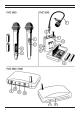
(B) Receiver unit (7) - (12)
7. Power-on lamp
8. RX reception indicator
9. Audio output socket
10. Volume control (squelch)
11. Channel selector switch
12. Low voltage socket
4. Operating elements
A. Transmitter unit
(1) Power-on lamp
This lamp comes on briefly when the microphone is switched on. If it stays on it signals that the batteries/battery
packs are discharged. These should then be replaced.
(2) ON/OFF switch
Switch to the „ON“ position when you wish to use the microphone and to the „OFF“ position to switch it off. When
the microphone is ready to use, the power-on lamp (A1) comes on briefly.
(3) Channel selector switch
Using this sliding switch up to 8 different transmission frequencies can be set. Transmission is possible only when
the channel selector switches on the transmitter and receiver are set to the same channel. Possible settings are
given in the table under B 11, channel selector switch.
(4) Battery compartment
To operate the appliance, insert two AA batteries or AA battery packs in this compartment, making sure that the
polarity of the batteries or battery packs is correct.
(5) Microphone socket
The electret lapel microphone included with the FMC 9040 is inserted into this socket and secured against
accidental removal by the thread provided.
(6) Variable sensitivity
If the volume/sensitivity of the microphone are insufficient, the default setting can be changed using the adjustment
tool.
(B) Receiver unit
(7) Power-on lamp
The power-on lamp lights when the receiver is ready to operate.
(8) RX reception indicator
This indicator lights when the microphone is switched on.
(9) Audio output socket
Using the mono audio lead provided, connect this socket to a hi-fi appliance fitted with a microphone input.
(10) Volume control (squelch)
You can use this control to set the volume of the transmitted voice signals to your required level.
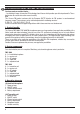
(11) Channel selector switch
You can set 8 different transmission channels as illustrated below. This allows maximum parallel operation of 4
microphone sets of the same type.
(12) Low voltage socket
This socket is suitable for connection of the 12 Volt AC adapter.
(C) AC adapter
12 Volt AC adapter for connecting the receiver to the mains.
(D) Audio lead
For connecting the receiver to hi-fi appliances with a microphone input 6.5 mm jack socket.
(E) Adjustment tool
Screwdriver to adjust the volume or sensitivity.
Channel 1 Channel 2 Channel 3 Channel 4 Channel 5 Channel 6 Channel 7 Channel 8