
User`s guide


SMPS AC/DC Reference Design User’s Guide
DS70320B-page 40 © 2008 Microchip Technology Inc.
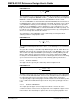
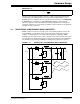
2.2.2.2 OUTPUT CHOKE
There are two output chokes in the current-doubler synchronous rectifier. Each
inductor's mean current is half the output current, and the fluxing voltage period occurs
in only half of the cycle. Therefore the ripple current is given by Equation 2-23.
EQUATION 2-23:
The choke is designed to have a 20% current ripple component, and the inductance is
selected to give 3.3A at the nominal input voltage 400V. Therefore, the inductance
needs to be 9 μH and the winding rated for a current of around 18A.
The Magnetics Kool Mu core iron loss can be computed from Equation 2-24.
EQUATION 2-24:
The peak flux density is computed from Equation 2-25.
EQUATION 2-25:
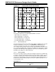
Taking the 20.3 mm OD core No. 77848 with an A
L
= 32 with A
e
= 22.6 mm
2
, the
required number of turns, N, is 17. Therefore, the peak-to-peak AC flux density is 77
mT and the core loss is 0.5W. According to the single-layer winding data, 1.6 mm OD
wire (14 AWG) will fit on the core so that the 13 x 0.315 mm will fit. The copper
cross-sectional area is 1.01 mm
2
, so the current density is 17.7A/mm
2
. The resistance
is estimated to be 7 mΩ (double the 14 AWG resistance) and so the copper loss is
2.2W. With forced air-cooling this is acceptable.
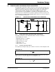
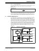
2.2.2.3 OUTPUT CAPACITOR
The main output capacitor is a 2200 μF, 25V electrolytic with two 10 μF, 25V multilayer
ceramic capacitors in parallel. The larger bulk capacitance provides the main energy
storage while the small ceramic capacitors with very low ESR provide the
high-frequency ripple current decoupling capability. The capacitor ripple current is the
combined AC components of the two output inductors plus the AC component of the
synchronous Buck loads. In the case of the inductor currents, this is lower compared
to a conventional output rectifier due to the 50% phase shift in the inductor currents,
and is dominated by current supplied to the synchronous Buck regulators. The
capacitor must also provide enough energy during a step load transient to maintain the
12V output voltage within the required regulated limits.
2
in
ripple o
VDT
I
V
Ln
⎛⎞
=−
⎜⎟
⎝⎠
2
1. 46
2
in
cosw
e
VDT
P
Vf
NA n
⎛⎞
⎛⎞
=−
⎜⎟
⎜⎟
⎝⎠
⎝⎠
W/m
3
p
k
pk
e
L
I
B
NA
=
T