
User`s guide


Hardware Design
© 2008 Microchip Technology Inc. DS70320B-page 45
2.4.1.3 OUTPUT CAPACITOR
The output capacitor ripple current is very low due to the continuous inductor currents
with phase shifting. The relationship for capacitor rms current is given by
Equation 2-34.
EQUATION 2-34:
Therefore, the total capacitor ripple current is 1.0 Arms. The output capacitor is made
up of three Rubycon 6.3ZL1500M10X20 1500 μF, 6.3V electrolytic capacitors plus
three 10 μF, 16V multi-layer ceramics in parallel. The electrolytic capacitors are each
rated to 1.82 Arms at 105ºC, and can easily handle the ripple current on their own.
2.5 AUXILIARY POWER SUPPLY
The supply voltages for the primary and secondary side dsPIC DSC device and gate
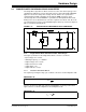
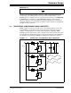
drive circuitry are generated by a simple low-power flyback SMPS. Figure 2-13
illustrates the main components in the design. The integrated high-voltage proprietary
controlled switch feeds a high-frequency transformer, and multiple secondary windings
tapped-off via a diode/capacitor circuit. The SMPS operates in discontinuous flyback
mode, so that energy is stored in the magnetizing inductance of the transformer during
the switch on-period, and transferred to the secondary circuits during the off-period. A
snubber arrangement is required across the transformer primary to dissipate the
transformer parasitic leakage energy and ensure that the switch voltage does not
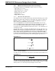
exceed its maximum rating. The typical flyback MOSFET waveforms are shown in
Figure 2-14.
FIGURE 2-13: AUXILIARY FLYBACK SMPS
312
cap
i
i
Δ
=
%
V
dc
Snubber/
Clamp
Control
SEC_17V
SEC_7V
SEC_0V
PRI_13V
PRI_7V