
User`s guide


SMPS AC/DC Reference Design User’s Guide
DS70320B-page 48 © 2008 Microchip Technology Inc.
From Equation 2-36, the on-time for the switch at 400V is 1.35 μs and the duty cycle is
0.19. Therefore, the rms current in the primary is 0.11 Arms. A suitable winding wire
diameter is 0.16 mm with 5.5 Amm
-2
. The 100ºC resistance of this wire is 1.1 Ωm
-1
, and
from the mean turn length of the bobbin (41.2 mm), the predicted primary resistance is
5Ω. Therefore, the primary copper loss is 60 mW.
The secondary turns must be selected to ensure that the referred voltage across the
TNY277 does not exceed its maximum blocking voltage rating and for discontinuous
current operation given the operating duty cycle. The peak voltage across the TNY277
when energy is transferred to the secondary is given by Equation 2-41.
EQUATION 2-41:
A sensible limit on the maximum switch voltage is 540V, so for the main 17V secondary
output, including a 0.8V diode forward voltage drop, the required turns ratio is 7.86.
Therefore, the secondary turns on the 17V winding is 14. A separate tapping at six
turns on this winding can be used for the 7V secondary. The secondary winding is
constructed using TEX-E wire to give the required 2500 Vrms galvanic voltage
isolation.
The time taken for the flyback transformer to be de-fluxed is given by Equation 2-42.
EQUATION 2-42:
Therefore, the off period is 3.9 μs, which is lower than the maximum available period
to ensure discontinuous operation under normal operating conditions.
The secondary peak and rms currents in the winding are given by the following formula
in Equation 2-43 and Equation 2-44.
EQUATION 2-43:
EQUATION 2-44:
Therefore, the secondary current in the main 17V output is 0.7 Arms. The secondary
winding resistance is 0.1Ω and the total copper loss in the secondary winding is
estimated to be 50 mW. Keeping a similar winding current density as the primary
means that a 0.4 mm wire gauge can be chosen for the secondary windings. The two
auxiliary supply windings on the primary side follow directly from the chosen
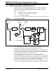
transformer turns ratio. The total transformer power dissipation is dominated by the iron
loss and is roughly 0.8W. This will lead to a temperature rise of 40ºC, based on the
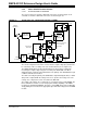
published thermal characteristics of an EF20 transformer. Figure 2-15 illustrates the
flyback transformer construction.
p
p
DC o
s
N
VV V
N
=+
s
pp
off
po
N
LI
t
N
V
=
2
o
s
off
TI
I
t
=
2
3
s
o
off
T
iI
t
=
%