
User`s guide


SMPS AC/DC Reference Design User’s Guide
DS70320B-page 52 © 2008 Microchip Technology Inc.
3.2 STRUCTURE OF THE CONTROL SOFTWARE
The control software for the SMPS AC/DC Reference Design essentially follows a
single basic structure as shown in Figure 3-2.
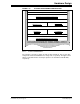
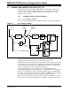
FIGURE 3-2: FLOWCHART OF CONTROL SOFTWARE
The control software uses a mixture of C programming and Assembly programming. All
time-critical functions are written in Assembly language. The main loop, peripheral
setup routines, initialization routines and non-critical functions are all written using the
C programming language.
The SMPS AC/DC Reference Design comprises of two separate projects, namely:
• Primary: This project contains the complete code for the primary side of the
SMPS AC/DC Reference Design. This includes the control software for the PFC
Boost Converter and the Phase-Shift ZVT Converter.
• Secondary: This project contains the complete code for the secondary side of the
SMPS AC/DC Reference Design. This includes the control software for the
Single-Phase Buck Converter and Multi-Phase Buck Converter, and also includes
code for the ZVT output voltage measurement and digital voltage feedback.
All of the functional blocks shown in Figure 3-2 are common to both projects. Brief
descriptions of each functional block are provided in subsequent sections.
Initialization
Start
Idle Loop
(Normal Operation)
Enable Peripherals
Fault Present?
Fault Loop
ADC Interrupt
Yes
No
Soft-Start