
User`s guide


SMPS AC/DC Reference Design User’s Guide
DS70320B-page 60 © 2008 Microchip Technology Inc.
As specified in Table 3-2, PWM1H, PWM1L, PWM2H, and PWM2L are the PWM
signals used for switching the Full-Bridge MOSFETs. PWM1H and PWM1L control one
leg of the Full-Bridge, while PWM2H and PWM2L control the second leg of the
Full-Bridge.
PWM1 and PWM2 are configured to operate in the complementary PWM mode and
approximately 250 kHz switching frequency. The duty cycle of these PWM signals is
fixed at 50%. Some dead time is also inserted to prevent shoot-through.
PWM3 is used for driving the synchronous rectifier MOSFETs on the secondary side
of the ZVT Transformer. PWM3 is also configured as a complementary mode PWM
signal with dead time. The PWM3 signal is configured identically to that of PWM1. The
output of the control loop directly modifies the phase of PWM2 to accomplish the
control of the output.
AN0 and AN2 both measure the ZVT current, but each input is sampled on opposite
peaks of the current signal. The conversion result of AN0 is used for the ZVT
overcurrent
fault protection. The voltage feedback is received on the U1RX pin of the
primary side dsPIC DSC.
The voltage loop is executed every two PWM periods, but the measured voltage is only
updated when data is received by the UART. This UART data reception is
asynchronous to the PWM drive signals.
3.3.3 Primary Side Software Time Management
Both the PFC and ZVT converters are controlled using a single dsPIC DSC. The
execution rates are carefully chosen to effectively utilize the available processing
bandwidth of the dsPIC DSC. The flexible PWM-ADC trigger feature of the
dsPIC33FJ16GS504 enables precise sampling of analog signals and interleaved
control loop execution.
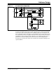
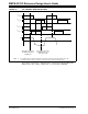
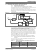
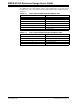
Figure 3-9 shows the interleaved control loop execution as implemented on the primary
side control software on the SMPS AC/DC Reference Design.
FIGURE 3-9: INTERLEAVED CONTROL LOOP EXECUTION
PWM1H
PWM1L
PWM2H
PWM2L
PWM4L
ZVT Trigger:
Once every 2 ZVT Cycles
PFC Current Trigger:
Once every 3 PFC Cycles
Sample and Convert
AN0, AN1
Execute
ZVT
Voltage
Loop
Sample and Convert
AN4, AN5
Execute
PFC
Current
Loop
Idle Loop
PFC Current Trigger:
Once every 3 PFC Cycles
Phase
Shift
Execute
ZVT
Voltage
Loop
Execute
ZVT
Voltage
Loop
Execute
PFC
Current
Loop
Sample and
AN4, AN5
ADC Pair 0
has highest
priority
Convert