
User`s guide


Software Design
© 2008 Microchip Technology Inc. DS70320B-page 65
3.5.2 Soft-Start Routine
Each individual stage of the SMPS AC/DC Reference Design employs a controlled
soft-start routine. At power-up, all reference set points are configured to produce 0V
output. Once the power-on delay has lapsed, the outputs begin their soft-start where
the reference set point is incremented until the desired output voltage is reached.
3.5.3 Overtemperature Protection
Temperature sensors are provided on the SMPS AC/DC Reference Design in two
positions. Overtemperature protection must be enabled to prevent damage to the
system in the event of:
• Insufficient airflow in the system caused by a failure of the cooling fan
• Operation of the system at a high ambient temperature
The implementation detail for each sensor is described in the following sections.
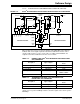
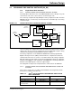
3.5.3.1 PCB OVERTEMPERATURE PROTECTION
One of the PCB temperature sensors is located on the secondary side in the middle of
the four Buck phases. The other temperature sensor is located on the primary side just
below the Boost inductor (L4). An analog temperature sensor is chosen that outputs an
analog voltage proportional to the measured temperature.
The output of the temperature sensor is connected to analog input AN8 on the
secondary side dsPIC DSC, and AN10 on the primary side dsPIC DSC. The PCB
temperature is measured in the ADC ISR and checked for overtemperature protection
in the fault loop. The maximum temperature set point is configured to approximately
90°C. If the measured temperature exceeds the maximum set point, a fault is
generated and the PWM outputs are turned OFF.
3.5.4 Input AC Undervoltage/Overvoltage Protection
The PFC Boost Converter is designed to operate normally for input voltages in the
range 85V–265V. In the event of an undervoltage condition, the circuit components will
undergo excessive stress due to the additional current drawn by the system to deliver
maximum output power. Therefore, undervoltage and overvoltage faults must be
implemented to prevent damage to the system and load. In the event of an overvoltage
condition, the input voltage may exceed the device ratings.
There are instances when the power grid may exhibit momentary voltage fluctuations,
which must be ignored by the system.
The input AC voltage protection is implemented in software by calculating the average
input voltage in the ADC ISR. The average input voltage is calculated as a part of the
PFC control scheme, and is checked in the fault loop to detect a sustained
undervoltage/overvoltage condition.
The first time an undervoltage/overvoltage condition is detected, a counter is
incremented. If the undervoltage/overvoltage condition remains for an extended period
of time, a fault is generated and the outputs are turned OFF.
3.5.5 Fault Source Identification
If a Fault condition is detected, it is often required that the system be turned OFF to
prevent damage. The PWM module on the dsPIC33FJ16GS504 has a built-in latched
fault mode. Using the latched fault mode, certain faults will immediately disable the
PWM outputs with no software overhead.
Each fault is assigned a fault ID to indicate the source of the last fault that occurred. A
visual indication is also provided using LEDs on both the primary and secondary side
of the SMPS AC/DC Reference Design.