
User's Manual


SR1520 Installation and User Guide Page 9
SR1520 Installation & User Guide Ver. 0.01
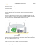
Avoid any partial line of sight between the antennas
Be cautious of trees or other foliage that may be near the path, or may grow and obstruct the
path
Be sure there is enough clearance from buildings and that no building construction may
eventually block the path
Check the topology of the land between the antennas using topographical maps, aerial photos,
or even satellite image data (software packages are available that may include this
information for your area)
Install the device at the customer home rooftop at a spot that meets the above requirements.
1.1.3 Device Height
A reliable wireless link is achieved by mounting the antennas at each end, high enough for a clear radio
LOS (line of sight) between them. The minimum height required depends on the distance of the link,
obstacles that may be in the path, topology of the terrain, and the curvature of the earth (for links over 3
miles). Use the following table to estimate the required minimum clearance above the ground or path
obstruction.
1.1.4 Antenna Position and Polarization
Once the required antenna height has been determined, other factors affecting the precise position of the
CPE to be considered are given below.
Ensure that there are no other radios/antennas within 2 m (6 ft) of the wireless router. These include
other WLAN radios/antennas.
Place the wireless router away from power and telephone lines
Avoid placing the CPE too close to any metallic reflective surfaces, such as roof-installed air-
conditioning equipment, tinted windows, wire fences, or water pipes. Ensure that there is at least 5
feet clearance from such objects
The CPE should be aligned/matched polarization to the AP to maximize throughput.