ViVOpay® 8100 User Guide Revision 1.0 ViVOtech, Inc. 451 El Camino Real, Santa Clara, CA 95050 Ph: (408) 248-7001 Email: info@vivotech.com URL: www.vivotech.
Copyright© 2010, ViVOtech® Inc. All rights reserved. ViVOtech, Inc. 451 El Camino Real Santa Clara, CA 95050 Written and designed at ViVOtech, Inc. This document, as well as the hardware and software it describes, is furnished under license and may only be used in accordance with the terms of such license. The content of this paper is furnished for informational use, subject to change without notice, and not to be construed as a commitment by ViVOtech, Inc. ViVOtech, Inc.
Table of Contents Chapter 1 Getting Started . . . . . . . . . . . . . . . . . . . . . . . . . . . . . . . . . . . . . . . . . . . . . 1 Overview . . . . . . . . . . . . . . . . . . . . . . . . . . . . . . . . . . . . . . . . . . . . . . . . . . . . . 1 Features . . . . . . . . . . . . . . . . . . . . . . . . . . . . . . . . . . . . . . . . . . . . . . . . 1 Unpacking the ViVOpay 8100 . . . . . . . . . . . . . . . . . . . . . . . . . . . . . . . . . . . . . 2 Accessories . . . . . . . . . . . . . . . . . . .
Security Elements Test . . . . . . . . . . . . . . . . . . . . . . . . . . . . . . . . . 21 Test Results Summary . . . . . . . . . . . . . . . . . . . . . . . . . . . . . . . . . 21 Maintenance . . . . . . . . . . . . . . . . . . . . . . . . . . . . . . . . . . . . . . . . . . . . . . . . . . 22 Upgrading the Firmware . . . . . . . . . . . . . . . . . . . . . . . . . . . . . . . . . . . 22 Appendix A Specifications . . . . . . . . . . . . . . . . . . . . . . . . . . . . . . . . . . . . . . . . . . . .
Chapter 1 Getting Started Overview The ViVOpay 8100 seamlessly integrates with existing POS systems and requires minimal counter space at checkout stands. The ViVOpay 8100 is a PCI 2.1 certified counter-top contactless reader with integrated display, MSR, function keys, and PIN pad. This device features serial RS-232 and USB 2.0 communications to POS systems.
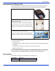
Getting Started Unpacking the ViVOpay 8100 The ViVOpay 8100 requires a data cable and a power supply if you are not powering the reader through the data cable. Verify that you have all the required components for the installation.
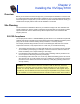
Chapter 2 Installing the ViVOpay 8100 Overview Before you connect and mount the ViVOpay 8100, you should plan the installation to conform to PCI 2.1 requirements and minimize radio frequency interference. Once you have determined the location and mounting of the ViVOpay 8100, you can connect it to power and the POS terminal. Finally, you should test the ViVOpay 8100 to make sure the installation is successful. Site Planning Two environmental considerations affect how you install the ViVOpay 8100.
Installing the ViVOpay 8100 Hardware Viewing Angles The information in this section will help you position the ViVOpay 8100 so that it conforms with PCI 2.1 requirements.
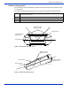
Installing the ViVOpay 8100 Horizontal observation range 45 to 315° γ α ≥ 40° 90° 270° α ≥ 35° α ≥ 35° 315° 45° Figure 3. Horizontal protection angles Horizontal Angle β Remarks Vertical Angle α 315° ≤ β ≤ 45° Within this range of β the cardholder deters an observer with his/her body. N/A 45° ≤ β ≤ 90° 270° ≤ β ≤ 315° Within these ranges visual observation of the keypad is partially blocked by the cardholder. The protection angle α shall be at least 35°.
Installing the ViVOpay 8100 Additional Shielding At times it may be impossible to position the ViVOpay 8100 so that viewing PIN entry is blocked from all positions—especially from overhead cameras. In these instances, the cashier should advise the customer to use their other hand to block observation of PIN entry.
Installing the ViVOpay 8100 Retesting Requirements If PIN entry on the ViVOpay 8100 is observable in any of the above tests, you must reposition the ViVOpay 8100 and completely retest all locations to verify that PIN entry is not visible. Consider placing a display to block observation from that position. Repositioning the ViVOpay 8100 to block observance of PIN entry at one location may expose PIN entry to observation at another location.
Installing the ViVOpay 8100 Installing the ViVOpay 8100 This section describes how to install the ViVOpay 8100. The basic steps are: • • • Connect to power and POS Mount if required Test the installation Connecting the ViVOpay 8100 Accessing the Connectors The ViVOpay 8100 connectors are beneath a cover on the bottom of the reader. To access the connectors 1. Turn over the ViVOpay 8100 so that the connector cover is visible. 2.
Installing the ViVOpay 8100 3. Slide the connector cover away from the ViVOpay 8100. If the captive screw catches, invert the ViVOpay 8100 to remove the connector cover. Installing a SAM Card The ViVOpay 8100 has a single SAM card slot for an optional SAM card. If you are using a SAM card in your application, insert the SAM card as shown by the SAM card icon. Warning: Do not insert or remove a SAM card while the ViVOpay 8100 is powered. This will cause permanent damage to the SAM card.
Installing the ViVOpay 8100 2. Insert the power cable into the power connector. 3. Insert the data cable into the 10-pin RJ45 connector directly beside the power socket.
Installing the ViVOpay 8100 4. Pass the cables through the slots in the connector cover. Use the narrow slot for the power cable to provide strain relief. 5. 6. 7. 8. Replace the cover and secure it with the retaining screw. Turn the ViVOpay 8100 keypad side up. Attach the data cable from the ViVOpay 8100 to the appropriate port on the POS. Plug in the power supply if required or make sure the POS is powered on. The ViVOpay 8100 beeps twice and the left LED illuminates.
Installing the ViVOpay 8100 Mounting the ViVOpay 8100 to a Surface The ViVOpay 8100 can be mounted to a surface to prevent it from being accidently dislodged or repositioned. To mount the ViVOpay 8100 1. Drill four 3.5mm (9/64 inch) holes in the surface where the ViVOpay 8600 will be mounted. Use the hole spacing shown in Figure 4. 76.20 mm 3.0 inches Mounting Holes x4 76.20 mm 3.0 inches Figure 4. Mounting hole locations 2.
Installing the ViVOpay 8100 Mounting the Wedge Bracket The optional wedge bracket tilts the ViVOpay another 11° for greater privacy. The wedge bracket is fastened to the ViVOpay 8100 with the four mounting holes. To mount the wedge bracket 1. Align the mounting bracket over the mounting holes with the thickest end over the connector cover. 2. Fasten in place with four M3 screws as shown in Figure 5. Figure 5.
Installing the ViVOpay 8100 Testing the Installation After you have completed the installation and have checked for PCI 2.1 conformance, check that the ViVOpay 8100 and the POS are communicating correctly by performing a sample transaction. Testing a Contactless Read Present the contactless card/fob/phone flat against the touch screen and so that maximum surface area is parallel to the screen. When a card/fob/phone has been successfully read, the ViVOpay 8100 beeps and illuminates all four green LEDs.
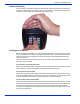
Installing the ViVOpay 8100 Testing a Magnetic Stripe Card Read To test the magnetic stripe reader, pass a test magnetic stripe card through the reader slot. Orient the card with the magnetic stripe at the bottom facing you as shown below. When a magnetic stripe card has been read successfully, the ViVOpay 8100 beeps and illuminates all four green LEDs. For an alternate test, see “Magstripe Test” on page 20.
Chapter 3 Troubleshooting and Maintenance Troubleshooting The ViVOpay 8100 readers are reliable and easy to troubleshoot. The components that may require troubleshooting include the power supply, the reader, and the data cable. Symptom Possible Cause Remedy • Reader not powered on. • Incorrect power supply used. • Check cable connections. • Verify that power is on and correct voltage and current are present. • Replace the power supply. • Verify that power cable plug is fully inserted.
Troubleshooting and Maintenance Onboard Diagnostics The ViVOpay 8100 has a built-in diagnostics program accessible through the RS-232 interface. If you did not purchase an RS-232 data cable with your ViVOpay 8100, you will need one to access the diagnositic tests. The Onboard Diagnostics (OBD) tests the following components of the ViVOpay 8100. Test Possible Results LCD Test Pass/Fail Touch Screen Test Pass/Fail. This test is not valid for the ViVOpay 8100.
Troubleshooting and Maintenance 4. Press the 1 key to enter the OBD. The ViVOpay AR Diagnostics menu displays. ViVOpay AR Diagnostics 0 1 2 3 4 5 6 7 8 9 Test Results Summary Test All LCD Touch Screen Keypad LEDs Tone Magstripe RFID and Antenna Security Elements X Exit The ViVOpay AR Diagnostics screen is the main menu. Test Results Summary The Test Results Summary displays the results of all tests performed. Once the ViVOpay 8100 is returned to normal mode, all results are cleared.
Troubleshooting and Maintenance 1. Press 2 from the ViVOpay AR Diagnostics screen. The AR LCD Test screen is displayed. AR LCD Test 1 Test all pixels ON (not run) 2 Test all pixels OFF (not run) 3 Test clarity of display (not run) CANCEL(X) Exit to main menu Select Test with 1, 2, or 3 and: Press ENTER (O) to pass test Press CANCEL (X) to fail test 2. Press 1. All pixels should be turned on and the screen should be a gray color. 3.
Troubleshooting and Maintenance LED Test This test asks you to verify that all of the LEDs are working correctly. The results will be displayed on the LCD. 1. Press 5 on the ViVOpay AR Diagnostics screen. The LED Test screen is displayed. LED Test Press Enter if all 4 LEDs are turned On and OFF, press X if not 2. Press ENTER if all four LEDs flash on and off in sequence otherwise, press CANCEL to indicate that the LEDs did not flash. The ViVOpay AR Diagnostics screen appears.
Troubleshooting and Maintenance 1. Press 7 on the ViVOpay AR Diagnostics screen. The Magstripe Test screen is displayed. Magstripe Test Swipe any Magstripe card 1. Swipe a card with a magnetic stripe through the slot on the top of the ViVOpay 8100. 2. The panel displays the results of the swipe; either the card has been successfully read or an error is indicated. 3. Press any key to return to the ViVOpay AR Diagnostics screen.
Troubleshooting and Maintenance 1. Press 9 on the ViVOpay AR Diagnostics screen. The Security Elements Test screen is displayed. Security Elements KPK Exists DUPKT exists Master session slots occupied -----6---Press any key to continue 2. Press any key to return to the ViVOpay AR Diagnostics main menu. Maintenance The ViVOpay 8100 contains no user-serviceable parts within its enclosure. Do not open the ViVOpay 8100 enclosure. WARNING: Attempting to open the ViVOpay 8100 enclosure will trigger PCI 2.
Troubleshooting and Maintenance 5. Double click the ViVO download utility icon or .exe to start the utility. 6. Power on the ViVOpay 8100. The bootloader version appears under the ViVOtech logo. 7. Click Download Image. 8. When prompted, locate and select the firmware (.hex file) to download and click OK. A progress bar indicates the status of the download. It will take approximately eight minutes to complete the download. 9. When the download is complete disconnect the ViVOpay 8100 from the PC and power.
Appendix A Specifications ViVOpay 8100 Specifications RF Interface Frequency 13.56 MHz Standard ISO 14443 Type A/B Physical Length 190.5 mm (7.5 in) Width 129.45 mm (5.1 in) maximum Depth 47.63 mm (1.875 in) Weight 0.4 Kg (0.9 lbs) Environmental Operating Temp. 0 to 40° C (32 to 104° F) Storage Temp. -10 to 70° C (-14 to 158° F) Operating Humidity 10 to 85% non-condensing Operating Environment Indoor only Power Voltage 9-12 Vdc regulated, +/- 10% Consumption 13.
Specifications Regulatory Compliance FCC Part 15 Class B Equipment This equipment has been tested and found to comply with the limits for a Class B digital device, pursuant to Part 15 of the FCC Rules. These limits are designed to provide reasonable protection against harmful interference in a residential installation.
Glossary Electronic Cash Register (ECR) The combination of a traditional cash register and a POS terminal, often PC-based. ExpressPay from American Express American Express contactless payment product that utilizes contactless technology. Firmware Software that is embedded in a hardware device that allows reading and executing the software, but does not allow modification, e.g., writing or deleting data by an end user.