AE-235 Infrared Illuminator Enclosure Installation Guide Rev. 1.
CAUTION: TO REDUCE RISK OF FIRE OR ELECTRIC SHOCK, DO NOT REMOVE COVER. NO USER SERVICEABLE PARTS INSIDE. REFER SERVICING TO QUALIFIED SERVICE PERSONNEL. UNPACKING: Unpack carefully. Electronic components can be damaged if improperly handled or dropped. If an item appears having been damaged in shipment, place it properly in its carton and notify the shipper. 1. Read and follow Instructions: All operating and user instructions should be read and followed before the unit is to be operated. 2.
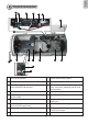
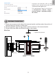
English Physical description II 11 12 13 14 15 16 17 1 2 3 7 6 9 8 10 5 4 1. Lens cap with heater 2. IR LEDs behind temper glass 3. IR board and IR board bracket 4. Thermostat switch 5. Day/Night trigger: controls the color/mono mode switch for D/N cameras 6. 7. Camera bracket 8. Universal IR control circuit board: to control color/mono switching and IR on/off synchronization Heater 9. Power Supply Unit: AC90~240V power input, DC12V output 11.
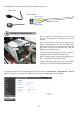
AC input wiring: connect power lines to an external power cord. Power cords Connector Block Brown: Line Yellow/Green: Earth Blue: Neutral III Interface Connections Once a camera is installed, you can connect the 12V DC phone jack connector to power the camera. Ground Since the housing comes with a light sensor, which controls when to turn into the night mode and light the IR LEDs. Connect the red or orange wire to the DI pin on the terminal block, and the black wire to the Ground pin.
The configuration option can be found in Configuration > Media > Image > General settings > Day/Night settings > IR cut filter. IV Hardware Installation 1. Loosen two screws on both sides of the camera bracket, and then adjust the position of camera bracket by sliding it up and down. 2. Use the supplied L-type hex key wrench to fix the camera on the camera bracket. 3. Connect the power cable and Ethernet cable to the camera.
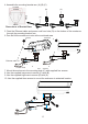
4. Assemble the mounting bracket arm (A).(B).(C). 110.00mm 83.00mm (B) (C) 95.00mm (A) 8.00mm Dimensions of Bracket Base 5. Feed the Ethernet cable and power cord from hole (D) on the bottom of the enclosure through the mounting bracket arm. 6. Pan and tilt the enclosure to aim at the monitored area. 6 5 (D) Ethernet cable Power cord 7. Mount the enclosure to the mounting plate (C) with supplied four screws. 8. Use the supplied long screw to secure (C) with (B). 9.