AE Series Outdoor Housing Installation Guide Ordering part no.: AE-238 AE-239 AE-243 AE-244 AE-23A AE-23B AE-23C AE-23D AE-23E-v2 AE-23F 900041102G 900041202G 900041902G 900042402G 900042302G 900042201G 900041701G 900041801G 900060000G 900042100G Rev. 1.
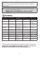
UNPACKING: Unpack carefully. Electronic components can be damaged if improperly handled or dropped. If an item appears damaged in shipment, place it properly in its carton and notify the shipper. IMPORTANT!: 1. Read and follow Instructions: All operating and user instructions should be read and followed before the unit is to be operated. connections.
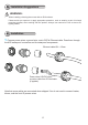
Revision History: Rev. 1.0: Initial release. Rev. 1.1: Added the Accessory list and updated environmental parameters: Added the distribution board drawing for the AE-23E and -23F. Rev. 1.3 revise specification and part number of AE-23E/23F Package Contents: 1. T30 L wrench. 2. 2x M4x8 3. Truss head screw: 1x 1/4"-20X1/4" 4. Truss head screw: 1x 1/4"-20X3/8" 5. 1x Plastic buffer plate: IMPORTANT: 1.
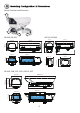
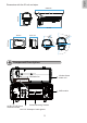
II Swivel Positions and Directions AE-238, AE-239 AE-243, AE-244 170 mm 415 mm 415 mm 206.9 mm 125 mm 170 mm 400 mm 105 mm 400 mm 255 mm 77.4 mm 87.01 mm USABLE AREA 88.05 mm AE-23A, 23B, 23C, 23D, 23E-v2, 23F 502.8 mm 135.5 mm 170 mm 400 mm 105 mm 77.4 mm 158.
English Dimensions with the IR unit and wiper 217.4 mm 502.8 mm 417 mm 87.01 mm R9 6.5 135 mm 95˚ 45 6. R9 88.
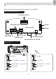
IV Installation Suggestions WARNING: • When installing a housing that comes with an IR illuminator: Please avoid eye exposure or apply appropriate protection, such as wearing a pair of Infrared protection glasses, when working with the product. Always use camera live view to oberve IR lighting effects. V Installation 1. Prepare power wires, a ground wire, and a CAT5e Ethernet cable. Pass them through the M16 waterproof connectors and its waterproof components. Ethernet cable Ø4 ~ 6.
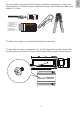
o: white/orange stripe O: orange solid g: white/green stripe B: blue solid b: white/blue stripe G: green solid br: white/brown stripe BR: brown solid o O g B b G br BR 1 2 3 4 5 6 7 8 2. When done, tighten up and install the waterproof connectors. 3. Assemble the camera components, e.g., the CS ring and lens module. Secure the mounting plate to the bottom of the camera (the label side) using the included screw.
Intrusion Alarm - Available on AE-23A/B/C/D/E/F. If preferred, install the intrusion alarm switch to the side of enclosure, and connect the detection wires to camera DI. 4. Adjust the camera's position so that the lens module can flush align with the tempered glass. Secure the camera using the screws and washers to the bottom of the housing.
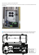
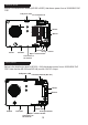
DC 12V output to the camera. You may also connect the 24V power to drive an external IRs. Below is the distribution board drawing power from 24V AC/DC. AE-23A, AE-23B, AE-23C, AE-23D I/O terminal block 24V AC/DC OUT Heater Power LED 12V DC OUT 24V AC/DC IN Camera heater Blower IR angle selector Connectors to the front IR AE-238, AE-243 Ground AE-238 AE-243 DC 12V OUT - to camera for IR LED AC 24V OUT - to external IR AC 24V OUT - to camera AC 24V IN AC 24V IN 9 English 5.
AE-23E-v2, AE-23F Below is the distribution board (AE-23E-v2/23F) that draws power from a 30/60/95W PoE PSE. PoE power LED I/O terminal block Heater Blower PoE IN 24V DC OUT IR angle selector Wiper / Camera heater Connectors to the front IR PoE OUT AE-239, AE-244 Below is the distribution board (AE-239, -244) that draws power from a 30/60/95W PoE PSE. Note that the AE-239 and AE-244 provide 12V DC output.
Facing the rear side of the housing, from left to right: DO2 DI2 RS485+ RS485DO+ DIDO1 DI1 Tank water pump control Wiper control, connects to IP camera's DO for manually triggering washer. RS485+, RS485 can be used to control IR illuminator beam angles, etc. RS485+5V VCC GND IR LED status, connects to IP camera's DI for IR status IR control, synchronizes day/night mode switching for IP camera. It is related to IR The AE-239/244 support DO signal from IR control board.
The following enclosures comes with adjustable IR lights: AE-23A/23B/23C/23D/23E-v2/23F-v2 HL HH LL LH beam angle for different effective illumination range. VAIR no.
output 1. IR control by IR light sensor The day/night mode DI connection enables the synchronization of IR light sensor and then automated day/night switching mechanism on the camera. AC/DC pwr RS485+ AC/DC pwr RS485- DI- DI3+ DI2+ DI1+ DI1 DO- IR ctrl DO1 DI- DO+ IR LED GND RS485+ DO2 DI2 5V VCC DO+ RS485- Tank ctrl Wiper ctrl Camera Terminal Block Enclosure Terminal Block AWG26 AWG20 DC12V AC24V 2.
2. IR control by Camera DO Camera will automatically trigger IR light on/off via DO. AC/DC pwr AC/DC pwr RS485+ RS485- DI- DI3+ DI2+ DI1+ DI1 DO- IR ctrl DO1 DI- DO+ IR LED GND RS485+ DO2 5V VCC DO+ RS485- Tank ctrl Wiper ctrl DI2 Camera Terminal Block Enclosure Terminal Block AWG26 Below is a diagram for water tank and wiper control. The wiper can be started by manually triggering the Digital Output from the camera user interface.
of the housing by driving two screws. Below are the mounting hole dimensions for the mounting brackets. Chances are you may need to plan for the locations of the brackets. AM-21D AM-811 AM-21E 15 AM-11F English 7.
8. Install the housing to the wall-mount bracket by aiming and pressing the spring mortise, and hook the bracket onto the groove in the spring mortise. Safety tether wire Secure the T30 anti-tamper screws on the other side using the included L-wrench. Connect the included safety wire between enclosure and bracket. If using other mount brackets, use the included M6 screws to secure the housing to the bracket. Use the mounting holes indicated below.
AM-21D AM-11F AM-811 Another two mounting holes in the front can be used use an IR bracket, AM-219. The bracket can be used to install external IRs. AM-219 17 English The AM-21D wall-mount, AM-11F, and AM-811 pendant brackets use the two mounting holes as indicated below.
If external IRs are installed, you can contact VIVOTEK for a different type of waterproof connectors for the 1/2" conduits. You can then route two of the conduits through the opening in the front of the bracket to the corresponding connectors on the IR illuminators. The 24V power wires to the IR illuminators are contained within. CaMate IR illuminators 9. Adjust zoom and focus and open a web console with the camera to tune for the best image.
M10 AM-314 AM-315 AM-414 3/4” conduit The mounting hole definition is illustrated below. The same mounting hole pattern apply to all polemount and corner-mount brackets. AM-21D Box: AA-351 AA-352 AM-718 AM-21E Outdoor PoE switch: AW-GEU-083A-240 AW-GET-083A-120 AW-GET-123A-240 AW-GEU-086A-240 AW-GET-086A-120 AW-GET-126A-240 Speed Dome: SD9361/62/63/64/65/66 SD83xx AM-212/221/220/21C 19 English Use the included M10 hex socket screws to secure the power box to a pole-mount or corner mount bracket.
If a power box or outdoor PoE switch is applied, Use the following mounting positions for the camera housings (via AM-21D and AM-21E). AM-21D AM-21E 10. If an IR illuminator is preferred, remove the metal cover from underneath the housing. Install the IR unit (AI-106, -108, -109) by fastening 4 T30 anti-tamper screws. Note that the bubber gasket should be in place when you install the unit.
English 11. Firmware configurable options: Open a web console with the camera. Use the Media > Focus function to tune for a best image focus on your target area. If preferred, e.g., shooting fast moving vehicles, select the 60fps frame rate.
Make sure that external IR is turned on in the night mode, and that the IR cut filter option is synchronized with the digital input you connected. In the night mode, check if the input signals are correctly detected. You may simulate the night mode by blocking the IR unit's light sensor. Change the triggering parameters when necessary.
English VI Appendix: RS485 Commands For housings that come with IR illuminators, wiper, and washer, commands can be delivered via the RS485 protocol. The RS485 connection uses the Pelco D protocol. Configuration parameters: Baud rate Data bits Parity Stop bit 2400 8 None 1 Command format: Byte1 Sync Byte2 Addr Byte3 CMND1 Byte4 CMND2 Byte5 DATA1 Byte6 DATA2 Byte7 CKSM Addr range: 0x00 ~ 0xFE. CKSM: check sum is the last 8 bits of the sum of Byte2 through Byte6.
LightSensorGate FF 01 00 18 03 LL CKSM For example, IRmode_Auto FF 01 00 18 02 02 1D IRmode_DI FF 01 00 18 02 03 1E IRmode_CMD FF 01 00 18 02 04 1F When the IR Mode Light Sensor Auto, the Lux value to turn IR LED can be configured. LL: Lux, changes is made by every10Lux For example: LightSensorGate = 100 FF 01 00 18 03 0A 26 LightSensorGate = 200 FF 01 00 18 03 14 30 The parameters of IR illuminator can be controlled via the RS485 connection.
VaIR Lens Stop FF 01 00 00 00 00 01 VAIR Lens Wide FF 01 00 40 00 00 41 VaIR Lens Tele FF 01 00 20 00 00 21 Wiper On FF 01 00 09 00 01 0B Wiper Off FF 01 00 0B 00 01 0D VaIR: The VAIR control include those on the IR Led and VaIR Lens.
This page is intentionally left blank.