
Installation Guide


4
Wiring
III
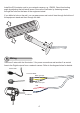
Install the IR illuminator next to your network camera, e.g., IP8352. Orient its shooting
angle by adjusting the ball swivel screw. Secure the illuminator by fastening screws
through the holes on the base of the equipment stand.
If you drilled a hole on the wall, you can pass power and control lines through the hollow of
the equipment stand and then through the hole
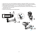
There are 5 wires with the illuminator: 3 for power connections and another 2 as control
lines to the Digital outputs from a network camera. Refer to the diagram below for details.
Black: AC input
Yellow: GND
White: AC input
To Camera
Red
Blue
Connector Block
Power cords