
Installation Guide


5
English
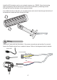
Power lines are connected to a connection block. Use them to connect the power cords
you separately purchased.
AC Power Connection
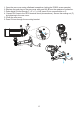
Disassemble the waterproof connector through which you will route your control lines to
the IR illuminator.
Control Line Connection
Rubber ring (A)
Screw nut (B)
Rubber seal (C)
Seal plugs (D)
Housing (E)
Sealing nut (F)
87654321 109
Digital output
Ground
Red
Blue
IP8352 GPIO Pinouts
Shown above is the network camera's General Purpose IO terminal block. Connect the IR
illuminator's red and blue lines to pin2 and pin4 on the terminal block.