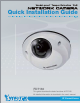
Vandal-proof . Tamper Detection . PoE Quick Installation Guide English ᖅϛ ᙏϛ Рҏᇭ Français Español Deutsch Português Italiano Türkçe Polski Русский Česky Svenska FD7130 This guide describes the basic functions of FD7130 All detailed information is described in the user's manual.
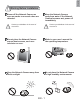
English Warning Before Installation Power off the Network Camera as soon as smoke or unusual odors are detected. Contact your distributor in the event of occurrence. Keep the Network Camera away from water. If the Network Camera becomes wet, power off immediately. Contact your distributor in the event of occurrence. Do not place the Network Camera around heat sources, such as a television or oven. Refer to your user’s manual for the operating temperature.
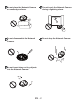
Do not place the Network Camera on unsteady surfaces. Do not touch the Network Camera during a lightning storm. Do not disassemble the Network Camera. Do not drop the Network Camera. Do not insert sharp or tiny objects into the Network Camera.
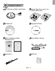
English 1 Package Contents Liquid Tight Connectors for RJ45 or M12 Cable FD7130 with an RJ45 or M12 Cable RJ45 RJ45 Software CD Alignment Sticker Quick Installation Guide / Warranty Card Ground Wire / Screws Screwdriver Silica Gel EN - 3 M12
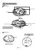
2 Physical Description Inner View Screw Holes Lens MicroSD/SDHC Card Slot Temperature Alarm Status LED The alarm will be triggered once the temparature inside the Network Camera reaches 60°C. Reset Button Outer View Record the MAC address before installing the camera. Network Camera Model No: FD7130 MAC:0002D107258A R o HS This device complies with part 15 of the FCC rules.
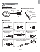
English 3 Cabling Assembly RJ45 Cable Connector Components of the Waterproof Connector RJ45 Cable Dimension (unit: mm) Sealing Nut (A) Seal (B) Screw Nut (C) Housing (D) Gasket (E) Assembling Steps 1 Prepare an Ethernet cable and strip part of the sheath. 2 Insert the housing into the screw nut. (C) 3 (D) Insert the seal into the housing. (B) Recommended cable gauge: 24AWG (0.51 mm) 4 Insert the stripped Ethernet cable through the sealing nut and the housing.
M12 Cable Connector Components of the Waterproof Connector M12 Cable Dimension (unit: mm) Sealing Nut (A) Seal (B) Clamp Ring (C) Gasket (D) Plastic Nut (E) Assembling Steps 1 Prepare an Ethernet cable and strip part of the sheath. 2 Insert the seal into the clamp ring. (B) 3 Insert the gasket into the clamp ring. (C) (D) Ø4.5mm~Ø6.5mm 4 Insert the stripped Ethernet cable through the sealing nut and the clamp ring.
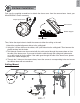
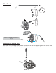
English 4 Hardware Installation First, use the supplied screwdriver to detach the dome cover from the camera base. Insert your MicroSD/SDHC Card if necessary. Tamper-proof Screw Dome Cover Rubber Stopper Camera Base Then, follow the steps below to install the camera to either the ceiling or the wall: 1. Attach the supplied alignment sticker to the ceiling/wall. 2. Using the 3 screw circles on the sticker, drill 3 pilot holes into the ceiling/wall. Then hammer the plastic anchors into the holes. 3.
Wall Mount 1 2 B A Please secure the screws tightly to avoid moisture. 3 4 Installing the Ground Wire As shown in the following figure, please secure one side of the supplied ground wire to the screw hole, then route the other side of the ground wire to the ground.
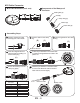
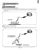
English 5 Network Deployment Power over Ethernet (PoE) When using a PoE-enabled switch This Network Camera is PoE-compliant, allowing transmission of power and data via a single Ethernet cable. Follow the below illustration to connect the camera to a PoE-enabled switch via Ethernet cable. PoE Switch POWER COLLISION 1 2 3 4 5 LINK RECEIVE PARTITION When using a non-PoE switch Use a PoE power injector (optional) to connect between the Network Camera and a non-PoE switch.
6 Assigning an IP Address 1. Install “Installation Wizard 2” from the Software Utility directory on the software CD. 2. The program will conduct an analysis of your network environment. After your network is analyzed, please click on the “Next” button to continue the program. Installation Wizard 2 3. The program will search for VIVOTEK Video Receivers, Video Servers, and Network Cameras on the same LAN. 4. After searching, the main installer window will pop up.
English 7 Ready to Use 1. Access the Network Camera on the LAN. 2. Retrieve live video through a web browser or recording software. For further setup, please refer to the user's manual on the software CD. 8 Adjusting the Lens To adjust the viewing angle Adjust the lens to a desired viewing angle as the diagram shown below. 10° 10° DO NOT over rotate the lens. Doing so will damage the camera lens module.
Fine-tune the Camera Focus The focus of this network camera is set from 1.0m to infinity by factory default. If you want to focus on objects closer than 1.0m or the lens has lost focus, please fine tune it in the following way. 1. Loosen the lens lock screw. 2. Manually rotate the lens to fine-tune the focus until the live image is clear. 3. Tighten the lens lock screw. Tighten the lens lock screw. 9 Completion Tear down the aluminum foil vacuum bag and take out the silica gel.
Copyright P/N: 625008801G Ver.1.1 2009 VIVOTEK INC. All right reserved.