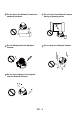
English Warning Before Installation Power off the Network Camera as soon as smoke or unusual odors are detected. Contact your distributor in the event of occurrence. Keep the Network Camera away from water. If the Network Camera becomes wet, power off immediately. Contact your distributor in the event of occurrence. Do not place the Network Camera around heat sources, such as a television or oven. Refer to your user's manual for the operating temperature.
Do not place the Network Camera on unsteady surfaces. Do not touch the Network Camera during a lightning storm. Do not disassemble the Network Camera. Do not drop the Network Camera. Do not insert sharp or tiny objects into the Network Camera.
English 1 Package Contents FD8161 Power Adapter Software CD Alignment Sticker 510000210G A/V Cable Quick Installation Guide / Warranty Card Screwdriver Screws and I/O Connector EN - 3
2 Physical Description Light Sensor IR LEDs Lens SD/SDHC Card Slot Tilt Adjustment Screw Built-in Microphone PIR Sensor Status LED Power Cord Socket Recessed Reset Button Ethernet 10/100 RJ45 Socket Focus Controller Zoom Controller Rotation Adjustment Screw Pan Adjustment Screw General I/O Terminal Block NTSC/PAL Switch Int. NTSC ON 1 2 1 2 3 4 AV Out Audio In Ext PAL Audio In Audio/Video Out External/Internal Microphone Switch Keep a note of the MAC address before installing the camera.
English 3 Hardware Installation First, use the supplied screwdriver to detach the dome cover from the camera base. Then, follow the steps below to install the camera to either the ceiling or the wall. Installation Tips Before installing the camera, look for a shooting area that best suits your needs. The built-in PIR (Passive Infrared) sensor will be triggered when a person enters its detection range.
4 Network Deployment General Connection (without PoE) 1. If you have external devices such as sensors and alarms, connect them to the general I/O terminal block. 2. Connect the camera to a switch via Ethernet cable. 3. Connect the power cable from the Network Camera to a power outlet. 1 1: Power 2: Digital output 3: Digital input 4: Ground Int.
English Power over Ethernet (PoE) When using a PoE-enabled switch This Network Camera is PoE-compliant, allowing transmission of power and data via a single Ethernet cable. Follow the below illustration to connect the Network Camera to a PoE-enabled switch via Ethernet cable. POWER COLLISION 1 2 3 4 5 LINK RECEIVE PARTITION PoE Switch When using a non-PoE switch Use a PoE power injector (optional) to connect between the Network Camera and a non-PoE switch.
5 Assigning an IP Address 1. Install “Installation Wizard 2” from the Software Utility directory on the software CD. 2. The program will conduct an analysis of your network environment. After your network is analyzed, please click on the “Next” button to continue the program. Installation Wizard 2 3. The program will search for VIVOTEK Video Receivers, Video Servers, and Network Cameras on the same LAN. 4. After searching, the main installer window will pop up.
English 6 Ready to Use 1. Access the Network Camera on the LAN. 2. Retrieve live video through a web browser or recording software. For further setup, please refer to the user's manual on the software CD.
7 Adjusting the Lens Based on the live image retrieved from the camera, adjust the camera lens by doing the following: To adjust the viewing angle 1. Loosen the pan adjustment screw and then turn the lens module left and right. Upon completion, tighten the screw. 2. Loosen the tilt adjustment screws on both side of the camera and then turn the lens module up and down. Upon completion, tighten the screws. 3. Loosen the rotation adjustment screw and then turn the lens to adjust the image orientation.
English To adjust the zoom factor and focus range 1. Loosen the zoom controller to adjust the zoom factor. Upon completion, tighten the zoom controller. 2. Loosen the focus controller to adjust the focus range. Upon completion, tighten the focus controller. 1 2 3 4 AV Out Audio In Ext PAL Loosen 1 2 ON Int. NTSC W N 8 8 Tighten T Completion 1. Rotate the black cover inside the dome cover to fit the lens shooting direction. 2. Attach the dome cover to camera. 3.