
User`s manual
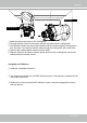
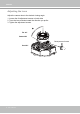

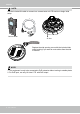

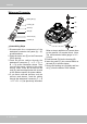
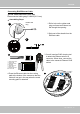
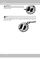
Table Of Contents
- Overview
- Accessing the Network Camera
- Using 3GPP-compatible Mobile Devices
- Using RTSP Players
- Using VIVOTEK Recording Software
- Main Page
- Client Settings
- Configuration
- System > General settings
- System > Homepage layout
- System > Logs
- System > Parameters
- System > Maintenance
- Media > Image
- Media > Video
- Media > Video
- Media > Audio
- Network > General settings
- Network > Streaming protocols
- Network > SNMP (Simple Network Management Protocol)
- Security > User Account
- Security > HTTPS (Hypertext Transfer Protocol over SSL)
- Security > Access List
- PTZ > PTZ settings
- Event > Event settings
- Applications > Motion detection
- Applications > DI and DO
- Applications > Tampering detection
- Applications > Audio detection
- Applications > VADP (VIVOTEK Application Development Platform)
- PIR
- Recording > Recording settings
- Local storage > SD card management
- Local storage > Content management
- Appendix

VIVOTEK
User's Manual - 17
IMPORTANT:
Connect power lines and if you have external devices such as sensors and alarms, make
the connection from the general I/O terminal block�
Cabling Assembly
Power and IO cables pass through a waterproof
connector� The Ethernet cable should be routed
through a rubber seal plug� All cables are user-
supplied�
The dome cover should be removed first because if it should fall during the installation
process, physical injury could occur to your co-workers�
For Ethernet Cable
For Power & IO Cables
Top View
Installation (FD8373)
Removing Dome Cover
First, use the included T20 hex key wrench to loose the four screws and detach the dome
cover from the camera base� Follow the steps below to install the camera either to a ceiling
or a wall�
Top View
Dome Cover
Dome Cover Retainer