IP8361 Bullet Network Camera User’s Manual 2MP • Outdoor • Day & Night Cable Management Rev. 1.
VIVOTEK Table of Contents Overview ������������������������������������������������������������������������������������������������������������������������������������������������������4 Read Before Use �������������������������������������������������������������������������������������������������������������������������������������4 Package Contents �����������������������������������������������������������������������������������������������������������������������������������4 Revision History ������
VIVOTEK Appendix ���������������������������������������������������������������������������������������������������������������������������������������������������������������� 115 URL Commands for the Network Camera ���������������������������������������������������������������������������������������������������������� 115 Technical Specifications ������������������������������������������������������������������������������������������������������������������������������������� 172 Technology License
VIVOTEK Overview VIVOTEK IP8361 is a high-end 2-megapixel network bullet camera surveillance. outdoor-specific features such as concealed wiring to prevent tampering, the IP8361 is the camera of choice for applications such as parking lots, gas stations, and building entrances. The IP8361 boasts high-definition 2-megapixel (1600 x 1200) resolution, allowing for the delivery of extremely detailed images and coverage 6 times larger than a VGA camera.
VIVOTEK Revision History Rev. 1.0: Initial release Rev. 1.1: Removed DC power adapter from the package contents; added DO connection diagrams. Symbols and Statements in this Document i INFORMATION: provides important messages or advices that might help prevent inconvenient or problem situations. NOTE: Notices provide guidance or advices that are related to the functional integrity of the machine. Tips: Tips are useful information that helps enhance or facilitae an installation, function, or process.
VIVOTEK Physical Description Lens IR LEDs Light Sensor SD/SDHC/SDXC Card Slot General I/O Terminal Block Reset Button Status LED Power Cord Socket RJ45 Cable General I/O Terminal Block This Network Camera provides a general I/O terminal block which is used to connect external input / output devices. The pin definitions are described below.
VIVOTEK DI/DO Diagram Please refer to the following illustration for the connection method. 12V PIN 1 Power+12V PIN 2 Digital output +12V PIN 3 Digital input PIN 4 Ground Gnd Camera Power BJT transistor 4 Gnd VDC 1 Input 3 Output 2 Camera Power +30 VDC Max. Switch BJT transistor 4 1 Input 3 Output 2 VDC +12 VDC Switch Relay Relay Status LED The LED indicates the status of the Network Camera. Item 1 2 3 4 5 LED status Steady Red Red LED Off Steady Red Red Blinks every 2 sec.
VIVOTEK Hardware Reset Reset Button Status LED The reset button is used to reset the system or to restore factory defaults. Sometimes resetting the system can return the camera to normal operation. If the system problems remain after reset, restore the factory settings and install again. Reset: Press and release the recessed reset button with a paper clip or thin object. Wait for the Network Camera to reboot. Restore: Press and hold the recessed reset button until the status LED rapidly blinks.
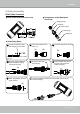
VIVOTEK Cabling Assembly RJ45 Cable Connector Components of the Waterproof Connector RJ45 Cable Dimension (unit: mm) Sealing Nut (A) Seal (B) Screw Nut (C) Housing (D) Gasket (E) Assembling Steps 1 Prepare an Ethernet cable and strip part of the sheath. 2 Insert the housing into the screw nut. (C) 3 (D) Insert the seal into the housing. (B) Recommended cable gauge: 24AWG (0.51 mm) 4 Insert the stripped Ethernet cable through the sealing nut and the housing.
VIVOTEK Hardware Installation 1. Attach the alignment sticker to the wall. Drill four holes into the wall. Then hammer the supplied plastic anchors into the holes and secure the plate with supplied screws. 2. Fix the intersection bracket to the side of the Network Camera with two screws. 3. Feed the RJ45 cable through the front opening of the wall mount bracket. (If you want to use external devices such as sensors and alarms, please refer to the assembling steps on the next page.) 4. Open the lens cover.
VIVOTEK Waterproof Connector Components of the Waterproof Connector Pin Definition Screw Nut (A) Seal (B) Housing (D) Sealing Nut (E) 1 2 3 4 5 6 7 8 1 2 3 4 Seals (C) Assembling Steps 1 2 3 4 5 6 7 8 Power +12V Digital Output Digital Input Ground AC 24V AC 24V RS485 + RS485 - 1 2 3 4 External MIC In Ground Audio Out Ground 1. Disassemble the components of the waterproof connector into part (A) ~ (E) as shown above. 2. Open the back cover of the Network Camera. 3.
VIVOTEK Network Deployment Setting up the Network Camera over the Internet There are several ways to set up the Network Camera over the Internet. The first way is to set up the Network Camera behind a router. The second way is to utilize a static IP. The third way is to use PPPoE. Internet connection via a router Before setting up the Network Camera over the Internet, make sure you have a router and follow the steps below. 1.
VIVOTEK Internet connection with static IP Choose this connection type if you are required to use a static IP for the Network Camera. Please refer to LAN on page 41 for details. Internet connection via PPPoE (Point-to-Point over Ethernet) Choose this connection type if you are connected to the Internet via a DSL Line. Please refer to PPPoE on page 42 for details.
VIVOTEK Set up the Network Camera through Power over Ethernet (PoE) When using a PoE-enabled switch The Network Camera is PoE-compliant, allowing transmission of power and data via a single Ethernet cable. Follow the below illustration to connect the Network Camera to a PoE-enabled switch via an Ethernet cable.
VIVOTEK Software Installation Installation Wizard 2 (IW2), free-bundled software included on the product CD, helps you set up your Network Camera on the LAN. 1. Install IW2 under the Software Utility directory from the software CD. Double click the IW2 shortcut on your desktop to launch the program. 2. The program will conduct an analysis of your network environment. After your network environment is analyzed, please click Next to continue the program. 3.
VIVOTEK Ready to Use 1. A browser session with the Network Camera should prompt as shown below 2. You should be able to see live video from your camera. You may also install the 32-channel recording software from the software CD in a deployment consisting of multiple cameras. For its installation details, please refer to its related documents. 3. Unscrew the zoom controller to adjust the zoom factor. Upon completion, tighten the zoom controller. 4. Unscrew the focus controller to adjust the focus range.
VIVOTEK 5. Tighten the lens cover. 6. Open the back cover. 7. Tear down the aluminum foil vacuum bag and take out the silica gel. Attach the silica gel to the inner side of the back cover, then tighten the back cover. (Please replace the silica gel desiccant with a new one if you open the back cover after installation.) 6 7 5 NOTE: If you want to use the supplied sun shield for outdoor environments, please follow the steps below to install: 1. Tighten the supplied two coupler screws. 2.
VIVOTEK Accessories VIVOTEK also provides other accessories for versatile applications as the following illustrations. Please visit VIVOTEK's official website for more purchase information. Pole Mount Bracket Corner Mount Bracket IR illuminator (distance 30m, 60°) Built-in 24 LED units (distance 25m, 35°) ° 60 ° 35 The 30m, 60° IR illuminator extends the coverage of the Network Camera and reduces the halo effect around captured images.
VIVOTEK Accessing the Network Camera This chapter explains how to access the Network Camera through web browsers, RTSP players, 3GPP-compatible mobile devices, and VIVOTEK recording software. Using Web Browsers Use Installation Wizard 2 (IW2) to access to the Network Cameras on the LAN. If your network environment is not a LAN, follow these steps to access the Netwotk Camera: 1. Launch your web browser (ex. Microsoft® Internet Explorer, Mozilla Firefox, or Netscape). 2.
VIVOTEK ► By default, the Network Camera is not password-protected. To prevent unauthorized access, it is highly recommended to set a password for the Network Camera. For more information about how to enable password protection, please refer to Security on page 34. ► If you see a dialog box indicating that your security settings prohibit running ActiveX ® Controls, please enable the ActiveX ® Controls for your browser. 1. Choose Tools > Internet Options > Security > Custom Level. 2.
VIVOTEK IMPORTANT: • Currently the Network Camera utilizes 32-bit ActiveX plugin. You CAN NOT open a management/view session with the camera using a 64-bit IE browser. • If you encounter this problem, try execute the Iexplore.exe program from C:\ Windows\SysWOW64. A 32-bit version of IE browser will be installed. • On Windows 7, the 32-bit explorer browser can be accessed from here: C:\Program Files (x86)\Internet Explorer\iexplore.
VIVOTEK Using RTSP Players To view the MPEG-4 streaming media using RTSP players, you can use one of the following players that support RTSP streaming. Quick Time Player VLC Media Player mpegable Player 1. Launch the RTSP player. pvPlayer 2. Choose File > Open URL. A URL dialog box will pop up. 3.
VIVOTEK Using 3GPP-compatible Mobile Devices To view the streaming media through 3GPP-compatible mobile devices, make sure the Network Camera can be accessed over the Internet. For more information on how to set up the Network Camera over the Internet, please refer to Setup the Network Camera over the Internet on page 12. To utilize this feature, please check the following settings on your Network Camera: 1.
VIVOTEK Using VIVOTEK Recording Software The product software CD also contains an ST7501 recording software, allowing simultaneous monitoring and video recording for multiple Network Cameras. Please install the recording software; then launch the program to add the Network Camera to the Channel list. For detailed information about how to use the recording software, please refer to the user’s manual of the software or download it from http://www.vivotek.com.
VIVOTEK Main Page This chapter explains the layout of the main page. It is composed of the following sections: VIVOTEK INC. Logo, Host Name, Camera Control Area, Configuration Area, Menu, and Live Video Window. VIVOTEK INC. Logo Host Name Camera Control Area Configuration Area Live View Window VIVOTEK INC. Logo Click this logo to visit the VIVOTEK website. Host Name The host name can be customized to fit your needs. For more information, please refer to System on page 32.
VIVOTEK Configuration Area Client Settings: Click this button to access the client setting page. For more information, please refer to Client Settings on page 29. Configuration: Click this button to access the configuration page of the Network Camera. It is suggested that a password be applied to the Network Camera so that only the administrator can configure the Network Camera. For more information, please refer to Configuration on page 31.
VIVOTEK Pause: Pause the transmission of the streaming media. The button becomes the after clicking the Pause button. Stop: Stop the transmission of the streaming media. Click the transmission. Resume button Resume button to continue Start MP4 Recording: Click this button to record video clips in MP4 file format to your computer. Stop MP4 Recording button to end recording. When you exit the web browser, video Press the recording stops accordingly.
VIVOTEK Snapshot: Click this button to capture and save still images. The captured images will be displayed in a pop-up window. Right-click the image and choose Save Picture As to save it in JPEG (*.jpg) or BMP (*.bmp) format. Digital Zoom: Click and uncheck “Disable digital zoom” to enable the zoom operation. The navigation screen indicates the part of the image being magnified. To control the zoom level, drag the slider bar. To move to a different area you want to magnify, drag the navigation screen.
VIVOTEK Client Settings This chapter explains how to select the stream transmission mode and saving options on the local computer. When completed with the settings on this page, click Save on the page bottom to enable the settings. H.264/MPEG-4 Media Options Select to stream video or audio data or both. This is enabled only when the video mode is set to H.264 or MPEG-4. H.264/MPEG-4 Protocol Options Depending on your network environment, there are four transmission modes of H.
VIVOTEK MP4 Saving Options Users can record live video as they are watching it by clicking page. Here, you can specify the storage destination and file name. Start MP4 Recording on the main Folder: Specify a storage destination for the recorded video files. File name prefix: Enter the text that will be appended to the front of the video file name. Add date and time suffix to the file name: Select this option to append the date and time to the end of the file name.
VIVOTEK Configuration Click Configuration on the main page to enter the camera setting pages. Note that only Administrators can access the configuration page. VIVOTEK offers an easy-to-use user interface that helps you set up your network camera with minimal effort. To simplify the setting procedure, two types of user interfaces are available: Advanced Mode for professional users and Basic Mode for entry-level users.
VIVOTEK Advanced Mode Configuration List Click to switch to Basic Mode Each function on the configuration list will be explained in the following sections. Those functions that Firmware Version are displayed only in Advanced Mode are tabbed with Advanced Mode . If you want to set up advanced functions, please click [Advanced Mode] at the bottom of the configuration list to quickly switch over.
VIVOTEK System Time Keep current date and time: Select this option to preserve the current date and time of the Network Camera. The Network Camera’s internal real-time clock maintains the date and time even when the power of the system is turned off. Sync with computer time: Select this option to synchronize the date and time of the Network Camera with the local computer. The read-only date and time of the PC is displayed as updated. Manual: The administrator can enter the date and time manually.
VIVOTEK Security This section explains how to enable password protection and create multiple accounts. Root Password The administrator account name is “root”, which is permanent and can not be deleted. If you want to add more accounts in the Manage User column, please apply the password for the “root” account first. 1. Type the password identically in both text boxes, then click Save to enable password protection. 2.
VIVOTEK HTTPS (Hypertext Transfer Protocol over SSL) Advanced Mode This section explains how to enable authentication and encrypted communication over SSL (Secure Socket Layer). It helps protect streaming data transmission over the Internet on higher security level. Enable HTTPS Check this item to enable HTTPS communication, then select a connection option: "HTTP & HTTPS" or "HTTPS only". Note that you have to create and install a certificate first in the second column before clicking the Save button.
VIVOTEK 4. The Certificate Information will automatically de displayed in the third column as shown below. You can click Property to view detailed information about the certificate. 5. Click Home to return to the main page. Change the address from “http://” to “https://“ in the address bar and press Enter on your keyboard. Some Security Alert dialogs will prompt. Click OK or Yes to enable HTTPS. https:// https://192.168.5.151/index.
VIVOTEK Create self-signed certificate manually 1. Select this option. 2. Click Create to open the Create Certificate page, then click Save to generate the certificate. 3. The Certificate Information will automatically be displayed in the third column as shown below. You can click Property to see detailed information about the certificate. Create certificate and install : Select this option if you want to create a certificate from a certificate authority. 1. Select this option. 2.
VIVOTEK 3. If you see the following Information bar, click OK and click on the Information bar at the top of the page to allow pop-ups. 4. The pop-up window shows an example of a certificate request.
VIVOTEK 5. Look for a trusted certificate authority that issues digital certificates. Enroll the Network Camera. Wait for the certificate authority to issue a SSL certificate; click Browse... to search for the issued certificate, then click Upload in the second column. NOTE: ► How do I cancel the HTTPS settings? 1. Deselect the Enable HTTPS secure connection in the first column and click Save; a warning dialog will prompt. 2. Click OK to disable HTTPS. 3.
VIVOTEK SNMP (Simple Network Management Protocol) Advanced Mode This section explains how to use the SNMP on the network camera. The Simple Network Management Protocol is an application layer protocol that facilitates the exchange of management information between network devices. It helps network administrators to remotely manage network devices and find, solve network problems with ease. ■ The SNMP consists of the following three key components: 1.
VIVOTEK Network This section explains how to configure a wired network connection for the Network Camera. Network Type LAN Select this option when the Network Camera is deployed on a local area network (LAN) and is intended to be accessed by local computers. The default setting for the Network Type is LAN. Rememer to click Save when you complete the Network setting.
VIVOTEK Primary DNS: The primary domain name server that translates hostnames into IP addresses. Secondary DNS: Secondary domain name server that backups the Primary DNS. Primary WINS server: The primary WINS server that maintains the database of computer name and IP address. Secondary WINS server: The secondary WINS server that maintains the database of computer name and IP address.
VIVOTEK NOTE: ► If the default ports are already used by other devices connected to the same router, the Network Camera will select other available port numbers for the Network Camera. ► If UPnP TM is not supported by your router, you will see the following message: Error: Router does not support UPnP port forwarding. ► Below are steps to enable the UPnP TM user interface on your computer: Note that you must log on to the computer as a system administrator to install the UPnP TM components. 1.
VIVOTEK 4. In the Networking Services dialog box, select Universal Plug and Play and click OK. 5. Click Next in the following window. 6. Click Finish. UPnP TM is enabled. ► How does UPnP TM work? UPnP TM networking technology provides automatic IP configuration and dynamic discovery of devices added to a network. Services and capabilities offered by networked devices, such as printing and file sharing, are available among each other without the need for cumbersome network configuration.
VIVOTEK Enable IPv6 Select this option and click Save to enable IPv6 settings. Please note that this only works if your network environment and hardware equipment support IPv6. The browser should be Microsoft® Internet Explorer 6.5, Mozilla Firefox 3.0 or above. When IPv6 is enabled, by default, the network camera will listen to router advertisements and be assigned with a link-local IPv6 address accordingly. IPv6 Information: Click this button to obtain the IPv6 information as shown below.
VIVOTEK Please follow the steps below to link to an IPv6 address: 1. Open your web browser. 2. Enter the link-global or link-local IPv6 address in the address bar of your web browser. 3. The format should be: http://[2001:0c08:2500:0002:0202:d1ff:fe04:65f4]/ IPv6 address 4. Press Enter on the keyboard or click Refresh button to refresh the webpage.
VIVOTEK IEEE 802.1x Advanced Mode Enable this function if your network environment uses IEEE 802.1x, which is a port-based network access control. The network devices, intermediary switch/access point/hub, and RADIUS server must support and have their 802.1x settings enabled. The 802.1x standard is designed to enhance the security of local area networks, which provides authentication to network devices (clients) attached to a network port (wired or wireless).
VIVOTEK 3. When all settings are complete, move the Network Camera to the protected LAN by connecting it to an 802.1x enabled switch. The devices will automatically start the authentication process. NOTE NOTE: ► The authentication process for 802.1x: 1. The Certificate Authority (CA) provides the required signed certificates to the Network Camera (the supplicant) and the RADIUS Server (the authentication server). 2. A Network Camera requests access to the protected LAN using 802.
VIVOTEK QoS (Quality of Service) Advanced Mode Quality of Service refers to a resource reservation control mechanism, which guarantees a certain quality to different services on the network. Quality of service guarantees are important if the network capacity is insufficient, especially for real-time streaming multimedia applications. Quality can be defined as, for instance, a maintained level of bit rate, low latency, no packet dropping, etc.
VIVOTEK QoS/DSCP (the DiffServ model) Advanced Mode DSCP-ECN defines QoS at Layer 3 (Network Layer). The Differentiated Services (DiffServ) model is based on packet marking and router queuing disciplines. The marking is done by adding a field to the IP header, called the DSCP (Differentiated Services Codepoint). This is a 6-bit field that provides 64 different class IDs. It gives an indication of how a given packet is to be forwarded, known as the Per Hop Behavior (PHB).
VIVOTEK HTTP Advanced Mode To utilize HTTP authentication, make sure that your have set a password for the Network Camera first; please refer to Security on page 34 for details. Authentication: Depending on your network security requirements, the Network Camera provides two types of security settings for an HTTP transaction: basic and digest. If basic authentication is selected, the password is sent in plain text format and there can be potential risks of being intercepted.
VIVOTEK URL command -- http://:/ For example, when the Access name for stream 2 is set to video2.mjpg: 1. Launch Mozilla Firefox or Netscape. 2. Type the above URL command in the address bar. Press Enter. 3. The JPEG images will be displayed in your web browser. http://192.168.5.151/video2.
VIVOTEK Note that as JPEG only transmits a series of JPEG images to the client, to enable the two-way audio function, make sure the video mode is set to “MPEG-4” or "H.264" on the Audio and Video Settings page and the media option is set to “Video and Audio” on the Client Settings page. Please refer to Client Settings on page 29 and Audio and Video Settings on page 61.
VIVOTEK Advanced Mode To utilize RTSP streaming authentication, make sure that you have set a password for the Network Camera first; please refer to Security on page 34 for details. RTSP Streaming Authentication: Depending on your network security requirements, the Network Camera provides three types of security settings for streaming via RTSP protocol: disable, basic, and digest.
VIVOTEK RTSP port /RTP port for video, audio/ RTCP port for video, audio ■ RTSP (Real-Time Streaming Protocol) controls the delivery of streaming media. By default, the port number is set to 554. ■ The RTP (Real-time Transport Protocol) is used to deliver video and audio data to the clients. By default, the RTP port for video is set to 5556 and the RTP port for audio is set to 5558.
VIVOTEK DDNS This section explains how to configure the dynamic domain name service for the Network Camera. DDNS is a service that allows your Network Camera, especially when assigned with a dynamic IP address, to have a fixed host and domain name. DDNS: Dynamic domain name service Enable DDNS: Select this option to enable the DDNS setting. Provider: Select a DDNS provider from the provider drop-down list. VIVOTEK offers Safe100.net, a free dynamic domain name service, to VIVOTEK customers.
VIVOTEK [Register] Successfully Your account information has been mailed to registered e-mail address 4. Select Enable DDNS and click Save to enable the setting. ■ CustomSafe100 VIVOTEK offers documents to establish a CustomSafe100 DDNS server for distributors and system integrators. You can use CustomSafe100 to register a dynamic domain name if your distributor or system integrators offer such services. 1. In the DDNS column, select CustomSafe100 from the drop-down list. 2.
VIVOTEK Access List Advanced Mode This section explains how to control access permission by verifying the client PC’s IP address. General Settings Maximum number of concurrent streaming connection(s) limited to: Simultaneous live viewing for 1~10 clients (including stream 1 and stream 2). The default value is 10. If you modify the value and click Save, all current connections will be disconnected and automatically attempt to re-link (IE Explorer or Quick Time Player).
VIVOTEK ■ Refresh: Click this button to refresh all current connections. ■ Add to deny list: You can select entries from the Connection Status list and add them to the Deny List to deny access. Please note that those checked connections will only be disconnected temporarily and will automatically try to re-link again (IE Explorer or Quick Time Player). If you want to enable the denied list, please check Enable access list filtering and click Save in the first column.
VIVOTEK Network: This rule allows the user to assign a network address and corresponding subnet mask to the Allow/Deny List in the CIDR format. For example: IP address 192.168.2.x will be bolcked. Range: This rule allows the user to assign a range of IP addresses to the Allow/Deny List. This rule is only applied to IPv4 addresses. For example: ■ Delete Allowed/Denied list: In the Delete Allowed List or Delete Denied List column, make a selection and click Delete.
VIVOTEK Audio and Video This section explains how to cofigure the audio and video settings of the Network Camera. It is composed of the following two columns: Video Settings and Audio Settings. Video Settings Video title: Enter a name that will be displayed on the title bar of the live video. Video Title Title and Time Video 17:08:56 2008/06/25 Color: Select to display color or black/white video streams.
VIVOTEK to correct the image orientation. Please note that the preset locations will be cleared after flip/mirror. Overlay title and time stamp on video: Select this option to place the video title and time on the video streams. Note that when the frame size is set to 176 x 144 as shown in the picture below, only the time will be stamped on the video streams.
VIVOTEK White balance: Adjust the value for the best color temperature. ■ Auto The Network Camera automatically adjusts the color temperature of the light in response to different light sources. The white balance setting defaults to Auto and works well in most situations. ■ Keep current value Follow the steps below to manually set the white balance to compensate for the ambient lighting conditions. 1. Set the White balance to Auto and click Save. 2.
VIVOTEK You can click Preview to fine-tune the image, or click Restore to recall the original settings without incorporating the changes. When completed with the settings on this page, click Save to enable the setting and click Close to exit the page. Privacy Mask Advanced Mode Click Privacy Mask to open the settings page. On this page, you can block out sensitive zones to address privacy concerns. ■ To set the privacy mask windows, follow the steps below: 1. Click New to add a new window. 2.
VIVOTEK Sensor Settings Advanced Mode Click Sensor Settings to open the Sensor Settings page. On this page, you can set the maximum exposure time, exposure level, and AGC (Auto Gain Control) settings. You can configure two sets of sensor settings: one for normal situations, the other for special situations, such as day/night/schedule mode.
VIVOTEK If you want to configure another sensor setting for day/night/schedule mode, please click Profile to open the Sensor Settings Profile Settings page as shown below. 2012/05/05 Please follow the steps beolw to setup a profile: 1. Check Enable this profile. 2. Select the applied mode: Day mode, Night mode, or Schedule mode. Please manually enter a range of time if you choose Schedule mode. 3. Configure Exposure settings in the second column. Please refer to the previous page for detailed information.
VIVOTEK Viewing Window Advanced Mode Click Viewing Window to open the Viewing Window Settings page. This Network Camera supports multiple streams with frame size ranging from 176 x 144 to 1600 x 1200. The definition of multiple streams: ■ Stream 1: Users can define the "Region of Interest" (viewing region) and the "Output Frame Rate" (size of the live view window). ■ Stream 2: Users can define the "Region of Interest" (viewing region) and the "Output Frame Rate" (size of the live view window).
VIVOTEK Click Viewing Window to open the viewing region settings page. On this page, you can set the Region of Interest and the Output Frame Size for streams 1 ~ 3. Please follow the steps below to set up settings for a stream: 1. Select a stream which you want to set up the viewing region. If you want to stream out the video to a mobile device, please select stream 3. 2. Select a Region of Interest from the drop-down list.
VIVOTEK Cropping Setting Advanced Mode Click Cropping Setting to open the Cropping Settings page. Please follow the steps below to set up cropping mode for mutiple streams: 1. Click Cropping Setting to open the window as shown below. 2. Select a Captured area from the drop-down list. The floating frame, same as that in the Global View window on the home page, will resize accordingly.
VIVOTEK Video Quality Settings Click the stream item to display the detailed information. The maximum frame size will follow your settings in above sections. This Network Camera offers real-time H.264, MPEG-4, and MJEPG compression standards (triple codec) for real-time viewing. If H.264 or MPEG-4 mode is selected, the video is streamed via RTSP protocol.
VIVOTEK ■ Intra frame period Determine how often to plant an I frame. The shorter the duration, the more likely you will get better video quality, but at the cost of higher network bandwidth consumption. Select the intra frame period from the following durations: 1/4 second, 1/2 second, 1 second, 2 seconds, 3 seconds, and 4 seconds. ■ Video quality A complex scene generally produces a larger file size, meaning that higher bandwidth will be needed for data transmission.
VIVOTEK Day/Night Settings Switch to B/W in night mode Select this to enable the Network Camera to automatically switch to B/W during night mode. IR cut filter With a removable IR-cut filter, this Network Camera can automatically remove the filter to let IR light enter the sensor during low light conditions. ■ Auto mode The Network Camera automatically removes the filter by judging the level of ambient light.
VIVOTEK Audio Settings Mute: Select this option to disable audio transmission from the Network Camera to all clients. Note that if mute mode is turned on, no audio data will be transmitted even if audio transmission is enabled on the Client Settings page. In that case, the following message is displayed: External microphone input: Select the gain of the external audio input according to ambient conditions. Adjust the gain from +21 db (most sensitive) or -33 db (least sensitive).
VIVOTEK Motion Detection This section explains how to configure the Network Camera to enable motion detection. A total of three motion detection windows can be configured. 2012/05/05 Motion Detection Setting 1: For normal situations Follow the steps below to enable motion detection: Follow the steps below to enable motion detection: Motion Detection Setting 2: For special situations 1. Click New to add a new motion detection window. 2.
VIVOTEK A green bar indicates that even though motions have been detected, the event has not been triggered because the image variations still fall under the defined threshold. Percentage = 30% If you want to configure other motion detection settings for day/night/schedule mode, please click Profile to open the Motion Detection Profile Settings page as shown below. A total of three motion detection windows can be configured on this page as well.
VIVOTEK NOTE: ► How does motion detection work? A C B D There are two motion detection parameters: Sensitivity and Percentage. In the illustration above, frame A and frame B are two sequential images. Pixel differences between the two frames are detected and highlighted in gray (frame C) and will be compared with the sensitivity setting. Sensitivity is a value that expresses the sensitivity to moving objects.
VIVOTEK Camera Tampering Detection This section explains how to set up camera tampering detection. With tamper detection, the camera is capable of detecting incidents such as redirection, blocking, or defocusing, or even spray paint. Please follow the steps below to make use of the camera tamper detection function: 1. Select the Enable camera tampering detection checkbox. 2. Enter the tamper trigger duration. (10 sec. ~ 10 min.
VIVOTEK PTZ This section explains how to control the Network Camera’s Pan/Tilt/Zoom operation. There are two ways to enable the camera control function: 1. Mechanical: Connect the Network Camera to a PTZ driver or scanner via RS485 interface. 2. Digital: Control the e-PTZ operation. It allows users to quickly move the focus to a target area for close-up viewing without physically moving the camera. Please refer to page 83 for detailed instruction.
VIVOTEK Transparent HTTP Tunnel: If you want to use your own RS-485 device, you can use UART commands to build a Transparent HTTP Tunnel. The UART commands will be sent through HTTP tunnel established between the RS-485 device and the camera. For detailed application notes, please refer to URL Commands started on page 115 or http://www.vivotek.com/downloadfiles/support/appnote/14_document_1.pdf.
VIVOTEK Home page in Mechanical PTZ Mode The Preset Positions will also be displayed on the home page. Select one from the drop-down list, and the Network Camera will move to the selected preset position.
VIVOTEK Patrol Settings You can select some preset positions for the Network Camera to patrol through them. Please follow the steps below to set up a patrol schedule: 1. Click a preset location on the list and click Select. 2. The selected preset location will be displayed on the Source list. 3. Set the Dwelling time for the field of view to stay at the preset location during patrol. You can also manually enter a value in the blank and click Update. 4.
VIVOTEK Custom Command If Custom Camera (scanner) is selected as the PTZ driver, you will need to configure command buttons to control the PTZ scanner. Click Custom Command to open the Custom Command page to set the commands in the Control Settings session. Please refer to your PTZ scanner user's manual to enter the commands in the following fields. Click Save to enable the settings and click Close to exit the page.
VIVOTEK E-PTZ Operation If you select “Digital“, the e-PTZ control settings section will be displayed as shown below: Select Stream: Select one of the stream 1~3 to set up the e-PTZ control. Please note that each stream can be set up with its own e-preset positions and e-patrol settings. For detailed information about how to set up Preset Positions and Patrol Settings, please refer to page 79.
VIVOTEK Home page in E-PTZ Mode ■ The e-Preset Positions will also be displayed on the home page. Select one from the drop-down list, and the Network Camera will move to the selected e-preset position. ■ If you have set up different e-preset positions for stream 1~3, you can select one of the video streams to display its separate e-preset positions. Global View In addition to using the e-PTZ control panel, you can also use the mouse to drag or resize the floating frame to pan/tilt/zoom the viewing region.
VIVOTEK Homepage Layout Advanced Mode This section explains how to set up your own customized homepage layout. Preview This column shows the settings of your hompage layout. You can manually select the background and font colors in Theme Options (the third column on this page). The settings will be displayed automatically in this Preview field.
VIVOTEK Theme Options Here you can change the color of your homepage layout. There are three types of preset patterns for you to choose from. The new layout will simultaneously appear in the Preview filed. Click Save to enable the settings.
VIVOTEK ■ Follow the steps below to set up the customed homepage: 1. Click Custom on the left column. 2. Click the field where you want to change the color on the right column. Color Selector Custom Pattern 3. The palette window will pop up as shown below. 2 3 1 4 4. Drag the slider bar and click on the left square to select a desired color. 5. The selected color will be displayed in the corresponding fields and in the Preview column. 6. Click Save to enable the settings.
VIVOTEK Applications Advanced Mode This section explains how to configure the Network Camera to responds to particular situations (event). A typical application is that when a motion is detected, the Network Camera sends buffered images to an FTP server or e-mail address as notifications of the occurrences of events. In the illustrated on the right, an event can be triggered by many sources, such as motion detection or external digital input devices.
VIVOTEK Event Settings In the Event Settings column, click Add to open the Event Settings page. On this page, you can arrange three elements -- Trigger, Schedule, and Action to set an event. A total of 3 event settings can be configured. Event name: Enter a name for the event setting. Enable this event: Select this option to enable the event setting. Priority: Select the relative importance of this event (High, Normal, or Low). Events with a higher priority setting will be executed first.
VIVOTEK An event is an action initiated by a user-defined trigger source; it is the causal arrangement of the following three elements: Trigger, Event Schedule, and Action. Trigger This is the cause or stimulus which defines when to trigger the Network Camera. The trigger source can be configured to use the Network Camera’s built-in motion detection mechanism or external digital input devices. There are several choices of trigger sources as shown below.
VIVOTEK ■ Camera tampering detection This option allows the Network Camera to trigger when the camera detects that is is being tampered with. To enable this function, you need to configure the Tampering Detection option first. Please refer to page 77 for detailed information. Event Schedule Specify the period for the event. ■ Select days in a the week. ■ Select the recording schedule in 24-hr time format. Action Define the actions to be performed by the Network Camera when a trigger is activated.
VIVOTEK information. ■ Turn on IR illuminators for seconds Select this to turn on IR Illuminators when a trigger is activated every time or only in low light conditions. Specify the length of trigger interval in the text box. To set an event with recorded video or snapshots, it is necessary to configure the server and media settings so that the Network Camera will know what action to take (such as which server to send the media files to) when a trigger is activated.
VIVOTEK When the Event Status is ON, once an event is triggered by motion detection, the Network Camera will automatically send snapshots via e-mail. If you want to stop the event trigger, you can click on the ON button to turn it to OFF status or click Delete to remove the event setting. To remove a server setting from the list, select a server name from the drop-down list and click Delete. Note that only when the server setting is not applied or associated with an event setting can it be deleted.
VIVOTEK Server Settings Click Add Server on the Event Settings page to open the Server Setting page. On this page, you can specify where the notification messages are sent to when a trigger is activated. A total of 5 server settings can be configured. Server name: Enter a name for the server setting. Server Type There are four choices of server types available: Email, FTP, HTTP, and Network storage. Select the item to display the detailed configuration options. You can configure either one or all of them.
VIVOTEK FTP: Select to send the media files to an FTP server when a trigger is activated. ■ Server address: Enter the domain name or IP address of the FTP server. ■ Server port By default, the FTP server port is set to 21. It can also be assigned to another port number between 1025 and 65535. ■ User name: Enter the login name of the FTP account. ■ Password: Enter the password of the FTP account. ■ FTP folder name Enter the folder where the media file will be placed.
VIVOTEK HTTP: Select to send the media files to an HTTP server when a trigger is activated. ■ URL: Enter the URL of the HTTP server. ■ User name: Enter the user name if necessary. ■ Password: Enter the password if necessary. To verify if the HTTP settings are correctly configured, click Test. The result will be shown in a pop-up window as below. If successful, you will receive a test.txt file on the HTTP server. Click Save to enable the settings, then click Close to exit the page.
VIVOTEK Media Settings Click Add Media on the Event Settings page to open the Media Settings page. On this page, you can specify the type of media that will be sent when a trigger is activated. A total of 5 media settings can be configured. Media name: Enter a name for the media setting. Media Type There are three choices of media types available: Snapshot, Video Clip, and System log. Select the item to display the detailed configuration options. You can configure either one or all of them.
VIVOTEK Video clip: Select to send video clips when a trigger is activated. ■ Source: The source of video clip, which will be identical to the time shift caching stream. For more information about time shift caching stream, please refer to page 61. ■ Pre-event recording The Network Camera has a buffer area; the camera can temporarily hold data up to a certain limit. Enter a number to decide the duration of recording before a trigger is activated. The upper threshold is 9 seconds.
VIVOTEK You can continue to select a server and media type for the event. Please go back to page 94 for detailed information. ■ SD Test: Click to test your SD card. The system will display a message indicating success or failure. If you want to use your SD card for local storage, please format it before use. Please refer to page 101 for detailed information. ■ Create folders by date, time, and hour automatically: If you check this item, the system will generate folders automatically by date.
VIVOTEK The following is an example of a file destination with video clips: The format is: YYYYMMDD Click to open the directory 20081120 20081121 20081122 Click to delete all recorded data Click to delete selected items Click 20081120 to open the directory: The format is: HH (24r) Click to open the file list for that hour Click to go back to the previous level of the directory Click to delete selected items Click to delete all recorded data The format is: File name prefix + Minute (mm) You can set u
VIVOTEK Recording Advanced Mode This section explains how to configure the recording settings for the Network Camera. Recording Settings Insert your SD card and click here to test NOTE: ► Before setting up this page, please set up the Networked Storage on the Server Settings page first. ► Please remember to format your SD card when using for the first time. Please refer to page 105 for detailed information.
VIVOTEK If successful, you will receive a test.txt file on the networked storage share. 3. Enter a server name. 4. Click Save to complete the settings and click Close to exit the page. Recording Settings Click Add to open the recording setting page. In this page, you can define the recording source, recording schedule, and recording capacity. A total of 2 recording settings can be configured. Recording name: Enter a name for the recording setting.
VIVOTEK recording feature will activate the frame rate control. When enabled, recording takes place by recording only the I-frames (1x Intra-frame is recorded for every 1/2, 1, 2, or 4 seconds). And the full-frame-rate recording immediately takes place when a Motion Detection, DI, or Manual trigger is triggered. This feature is not directly related to the event notification settings in Applications > Event. Priority: Select the relative importance of this recording setting (High, Normal, and Low).
VIVOTEK ■ Click Recording setup (Name): Opens the Recording Settings page to modify. ■ Click ON (Status): The Status will become OFF and stop recording. ■ Click NAS (Destination): Opens the file list of recordings as shown below. For more information about folder naming rules, please refer to page 100 for details.
VIVOTEK Local Storage Advanced Mode This section explains how to manage the local storage on the Network Camera. Here you can view SD card status, search for recorded files to playback, download, etc. no SD card SD Card Management SD card status: This column shows the status and reserved space of your SD card. Please remember to format the SD card when using for the first time.
VIVOTEK SD card control ■ Enable cyclic storage: Check this item if you want to enable cyclic recording. When the maximum capacity is reached, the oldest file will be overwritten by the latest one. ■ Enable automatic disk cleanup: Check this item and enter the number of days you wish to retain a file. For example, if you enter “7 days”, the recorded files will be stored on the SD card for 7 days. Click Save to enable your settings.
VIVOTEK Search Results The following is an example of search results. There are four columns: Trigger time, Media type, Trigger type, and Locked. Click to sort the search results in either direction. Enter a key word to filter the Numbers of entries displayed on one page search results Highlight an item 2012 Click to switch pages View: Click on a search result which will highlight the selected item in purple as shown above.
VIVOTEK Download: Click on a search result to highlight the selected item in purple as shown above. Then click the Download button and a file download window will pop up for you to save the file. JPEGs to AVI: This functions only applies to “JPEG“ format files such as snapshots. You can select several snapshots from the list, then click this button. Those snapshots will be converted into an AVI file. Lock/Unlock: Select the desired search results, then click this button.
VIVOTEK System Log Advanced Mode This section explains how to configure the Network Camera to send the system log to the remote server as backup. Remote Log You can configure the Network Camera to send the system log file to a remote server as a log backup. Before utilizing this feature, it is suggested that the user install a log-recording tool to receive system log messages from the Network Camera. An example is Kiwi Syslog Daemon. Visit http://www.kiwisyslog. com/kiwi-syslog-daemon-overview/.
VIVOTEK View Parameters Advanced Mode The View Parameters page lists the entire system’s parameters in alphabetical order. If you need technical assistance, please provide the information listed on this page.
VIVOTEK Maintenance This chapter explains how to restore the Network Camera to factory default, upgrade firmware version, etc. Reboot This feature allows you to reboot the Network Camera, which takes about one minute to complete. When completed, the live video page will be displayed in your browser. The following message will be displayed during the reboot process. If the connection fails after rebooting, manually enter the IP address of the Network Camera in the address field to resume the connection.
VIVOTEK Export / Upload Files Advanced Mode This feature allows you to Export / Upload daylight saving time rules, custom language files, and setting backup files. Export daylight saving time configuration file: Click to set the start and end time of DST. Follow the steps below to export: 1. In the Export files column, click Export to export the daylight saving time configuration file from the Network Camera. 2. A file download dialog will pop up as shown below.
VIVOTEK Upload daylight saving time rule: Click Browse… and specify the XML file to upload. If the incorrect date and time are assigned, you will see the following warning message when uploading the file to the Network Camera. The following message is displayed when attempting to upload an incorrect file format. Export language file: Click to export language strings. VIVOTEK provides nine languages: English, Deutsch, Español, Français, Italiano, 日本語 , Português, 簡体中文 , and 繁體中文 .
VIVOTEK The following message is displayed when the upgrade has succeeded. Reboot system now!! This connection will close. The following message is displayed when you have selected an incorrect firmware file. Starting firmware upgrade... Do not power down the server during the upgrade. The server will restart automatically after the upgrade is completed. This will take about 1 - 5 minutes.
VIVOTEK Appendix URL Commands for the Network Camera Overview For some customers who already have their own web site or web control application, the Network Camera/Video Server can be easily integrated through URL syntax. This section specifies the external HTTP-based application programming interface. The HTTP-based camera interface provides the functionality to request a single image, control camera functions (PTZ, output relay etc.), and get and set internal parameter values.
VIVOTEK General CGI URL Syntax and Parameters CGI parameters are written in lower-case and as one word without any underscores or other separators. When the CGI request includes internal camera parameters, these parameters must be written exactly as they are named in the camera or video server. The CGIs are organized in functionally-related directories under the cgi-bin directory. The file extension .cgi is required. Syntax: http:///cgi-bin/[/...]/.
VIVOTEK http:///cgi-bin/operator/getparam.cgi?[] [&…] http:///cgi-bin/admin/getparam.cgi?[] [&…] Where the should be [_] or [.]. If you do not specify any parameters, all the parameters on the server will be returned. If you specify only , the parameters of the related group will be returned. client When querying parameter values, the current parameter values are returned.
VIVOTEK Set Server Parameter Values Note: The access right depends on the URL directory. Method: GET/POST Syntax: http:///cgi-bin/anonymous/setparam.cgi? = [&=…][&update=][&return=] http:///cgi-bin/viewer/setparam.cgi? = [&=…][&update=] [&return=] http:///cgi-bin/operator/setparam.
VIVOTEK where is =\r\n [] Only the parameters that you set and are readable will be returned. Example: Set the IP address of server to 192.168.0.123: Request: http://myserver/cgi-bin/admin/setparam.cgi?network_ipaddress=192.168.0.123 Response: HTTP/1.0 200 OK\r\n Content-Type: text/html\r\n Context-Length: 33\r\n \r\n network.ipaddress=192.168.0.
VIVOTEK blank A blank string. everything inside <> A description integer primary key SQLite data type. A 32-bit signed integer. The value is assigned a unique integer by the server. text SQLite data type. The value is a text string, stored using the database encoding (UTF-8, UTF-16BE or UTF-16-LE). coordinate x, y coordinate (eg. 0,0) window size window width and height (eg. 800x600) NOTE: The camera should not be restarted when parameters are changed.
VIVOTEK Vancouver -280: GMT-07:00 Mountain Time, Denver -281: GMT-07:00 Arizona -240: GMT-06:00 Central America, Central Time, Mexico City, Saskatchewan -200: GMT-05:00 Eastern Time, New York, Toronto -201: GMT-05:00 Bogota, Lima, Quito, Indiana -180: GMT-04:30 Caracas -160: GMT-04:00 Atlantic Time, Canada, La Paz, Santiago -140: GMT-03:30 Newfoundland -120: GMT-03:00 Brasilia, Buenos Aires, Georgetown, Greenland -80: GMT-02:00 Mid-Atlantic -40: GMT-01:00 Azores, Cape_Verde_IS.
VIVOTEK 280: GMT 07:00 Bangkok, Hanoi, Jakarta, Krasnoyarsk 320: GMT 08:00 Beijing, Chongging, Hong Kong, Kuala Lumpur, Singapore, Taipei 360: GMT 09:00 Osaka, Sapporo, Tokyo, Seoul, Yakutsk 380: GMT 09:30 Adelaide, Darwin 400: GMT 10:00 Brisbane, Canberra, Melbourne, Sydney, Guam, Vladivostok 440: GMT 11:00 Magadan, Solomon Is., New Caledonia 480: GMT 12:00 Aucklan, Wellington, Fiji, Kamchatka, Marshall Is.
VIVOTEK parameters will be restored to the default value except for a union of the combined results. restoreexceptdst 0, 7/6 Restore the system parameters to default values except all daylight saving time settings. This command can cooperate with other “restoreexceptXYZ” commands. When cooperating with others, the system parameters will be restored to default values except for a union of combined results.
VIVOTEK Group: status NAME VALUE SECURITY DESCRIPTION (get/set) di_i<0~(ndi-1)> 1/7 0 => Inactive, normal 1 => Active, triggered do_i<0~(ndo-1)> 1/7 0 => Inactive, normal 1 => Active, triggered vi_i<0~(nvi-1)> 1/7 Virtual input 0=> Inactive 1=> Active (capability.nvi>0) daynight day, night 7/7 Current status of day, night. onlinenum_rtsp integer 6/7 Current number of RTSP connections.
VIVOTEK user_i0_privilege viewer, 6/7 Root privilege 6/6 User privilege operator, admin user_i<1~20>_ viewer, privilege operator, admin Group: network NAME VALUE SECURITY DESCRIPTION (get/set) type lan, 6/6 Network connection type. pppoe preprocess 0~15 6/6 Stop related process before setting port value. resetip 6/6 1 => Get ipaddress, subnet, router, dns1, dns2 from DHCP server at next reboot. 0 => Use preset ipaddress, subnet, rounter, dns1, and dns2.
VIVOTEK certificate_size 6/7 Certificate file size (in bytes) privatekey_exist 6/6 Private key installed flag (for TLS) privatekey_time 6/7 Private key installed time. Represented in EPOCH privatekey_size 6/7 Private key file size (in bytes) SECURITY DESCRIPTION Subgroup of network: qos NAME VALUE (get/set) cos_enable 6/6 Enable/disable CoS (IEEE 802.
VIVOTEK port 80, 1025 ~ 65535 6/6 HTTP port. alternateport 1025~65535 6/6 Alternate HTTP port. authmode basic, 1/6 HTTP authentication mode. 1/6 HTTP server push access name for stream 1. digest s0_accessname string[32] (capability.protocol.spush_mjpeg =1 and video.stream.count>0) s1_accessname string[32] 1/6 HTTP server push access name for stream 2. (capability.protocol.spush_mjpeg =1 and video.stream.
VIVOTEK (capability.protocol.rtsp=1 and video.stream.count>1) s2_accessname string[32] 1/6 RTSP access name for stream3 (capability.protocol.rtsp=1 and video.stream.count>2) s3_accessname string[32] 1/6 RTSP access name for stream4 (capability.protocol.rtsp=1 and video.stream.count>3) s4_accessname string[32] 1/6 RTSP access name for stream5 (capability.protocol.rtsp=1 and video.stream.count>4) s0_audiotrack 6/6 The current audio track for stream1.
VIVOTEK Subgroup of network: rtp NAME VALUE SECURITY DESCRIPTION (get/set) videoport 1025 ~ 65535 6/6 Video channel port for RTP. (capability.protocol.rtp_unicast=1) audioport 1025 ~ 65535 6/6 Audio channel port for RTP. (capability.protocol.rtp_unicast=1) Subgroup of network: pppoe NAME VALUE SECURITY DESCRIPTION (get/set) user string[128] 6/6 PPPoE account user name. pass password[64] 6/6 PPPoE account password.
VIVOTEK Group: videoin NAME VALUE SECURITY DESCRIPTION (get/set) cmosfreq 50, 60 4/4 CMOS frequency. (videoin.type=2) (product dependent) whitebalance auto, manual 4/4 “auto” indicates auto white balance. “manual” indicates keep current value. atwbvalue<1~2> 0~ 4/4 Auto white balance value. 4294967295 (32-bit unsigned integer) exposurelevel 1~8 4/4 Exposure level (product dependent) autoiris 4/4 Enable auto Iris.
VIVOTEK Bit 4 => Support zoom operation; 0(not support), 1(support) Bit 5 => Support focus operation; 0(not support), 1(support) text string[16] 1/4 Enclose caption. imprinttimestamp 4/4 Overlay time stamp on video. maxexposure 1~480 4/4 Maximum exposure time. options quality, 4/4 Customize video quality first or video frame rate framerate, crop first. (product dependent) preoptions quality, 4/4 framerate, crop Previous customize video option.
VIVOTEK Group: videoin_c<0~(n-1)> for n channel products, and m is stream number NAME VALUE SECURITY DESCRIPTION (get/set) s<0~(m-1)>_codecty h264, mpeg4, pe mjpeg s<0~(m-1)>_resoluti VGA CMOS => on 176x144, 160x120, 320x240, 640x480 1.
VIVOTEK 352x288, 4CIF, 704x576 VS => QCIF, 176x120, 176x144, CIF, 352x240, 352x288, 4CIF, 704x480, 704x576 (product dependent) s<0~(m-1)>_enablee 4/4 Indicate whether to support eptz s<0~(m-1)>_mpeg4 250, 500, 1000, 4/4 Intra frame period in milliseconds. _intraperiod 2000, 3000, 4/4 cbr, constant bitrate ptz 4000 s<0~(m-1)>_mpeg4 cbr, vbr _ratecontrolmode s<0~(m-1)>_mpeg4 vbr, fix quality 1~5,99 4/4 _quant Quality of video when choosing vbr in “ratecontrolmode”.
VIVOTEK s<0~(m-1)>_h264_r cbr, vbr 4/4 atecontrolmode s<0~(m-1)>_h264_q cbr, constant bitrate vbr, fix quality 1~5,99 4/4 uant Quality of video when choosing vbr in “ratecontrolmode”. 0 is the customized manual input setting. 1 = worst quality, 5 = best quality. s<0~(m-1)>_h264_q 0~51 4/4 value s<0~(m-1)>_h264_b Manual video quality level input - choose customize input “h264_quant = 0” (for MPEG-4). 1000~8000000 4/4 itrate Set bit rate in bps when choosing cbr in “ratecontrolmode”.
VIVOTEK (product dependent) autoiris 4/4 Preview of enable auto Iris.
VIVOTEK itrate 5150, 5900, 6700, 7400, 7950, 10200, 12200 s<0~(m-1)>_ pcma, g711_mode pcmu 4/4 Set G.711 mode Group: image_c<0~(n-1)> for n channel products NAME VALUE SECURITY DESCRIPTION (get/set) brightness -5~5 4/4 Adjust brightness of image according to mode settings. saturation -5 ~ 5 4/4 Adjust saturation of image according to mode settings. contrast -5 ~ 5 4/4 Adjust contrast of image according to mode settings.
VIVOTEK to mode settings Group: timeshift, c for n channel products, m is stream number NAME VALUE SECURITY DESCRIPTION (get/set) enable 4/4 Enable time shift streaming. c<0~(n-1)>_s<0~( 4/4 Enable time shift streaming for specific stream. m-1)>_allow (product dependent) Group: motion_c<0~(n-1)> for m profile and n channel product NAME VALUE SECURITY DESCRIPTION (get/set) enable 4/4 Enable motion detection.
VIVOTEK ~2>_height profile_i<0~(m-1)>_win_i<0 0 ~ 100 4/4 Percent of motion detection window. 0 ~ 100 4/4 Sensitivity of motion detection window. ~2>_objsize profile_i<0~(m-1)>_win_i<0 ~2>_sensitivity Group: tampering_c<0~(n-1)> for n channel product NAME VALUE SECURITY DESCRIPTION (get/set) enable 4/4 Enable or disable tamper detection. threshold 0 ~ 255 4/4 Threshold of tamper detection.
VIVOTEK Group: upnppresentation NAME VALUE SECURITY DESCRIPTION (get/set) enable 6/6 Enable or disable the UPNP presentation service. Group: upnpportforwarding NAME VALUE SECURITY DESCRIPTION (get/set) enable 6/6 Enable or disable the UPNP port forwarding service. upnpnatstatus 0~3 6/7 The status of UpnP port forwarding, used internally.
VIVOTEK patrolseq string[64] 1/4 (For external device) The indexes of patrol points, separated by “,” patroldwelling string[128] 1/4 (For external device) The dwelling time of each patrol point, separated by “,” preset_i<0~(npre string[40] 1/4 Name of the preset location. 0~999 1/4 The dwelling time of each preset location. 0 ~ (m-1), m 1/4 Select corresponding uart set-1)>_name preset_i<0~(npre set-1)>_dwelling uart is UART count (capability.nuart>0).
VIVOTEK 2-2 uartmode rs485, 4/4 RS485 or RS232. 4/4 Set the flag to true to apply change in UART rs232 uartreset configuration. customdrvcmd_i< string[128] 1/4 PTZ command for custom camera. string[40] 1/4 Additional PTZ command name. string[128] 1/4 Additional PTZ command list. 1 7/4 Set this flag to true to apply change in custom command 0~9> speedlink_i<0~4> _name speedlink_i<0~4> _cmd updatecustomdrvc md updatespeedlinkc configuration.
VIVOTEK Group: layout NAME VALUE SECURITY DESCRIPTION (get/set) logo_default 1/6 0 => Custom logo 1 => Default logo logo_link string[40] 1/6 Hyperlink of the logo logo_powerbyvvtk_hidden 1/6 0=>display the power by vivotek logo 1=>hide the power by vivotek logo theme_option 1~4 1/6 1~3: One of the default themes. 4: Custom definition. theme_color_font string[7] 1/6 Font color. theme_color_configfont string[7] 1/6 Font color of configuration area.
VIVOTEK Group: capability NAME VALUE SECURITY DESCRIPTION (get/set) api_httpversion 0200a 0/7 The HTTP API version. bootuptime 0/7 Server bootup time. nir 0, 0/7 Number of IR interfaces. 0/7 Number of PIRs. 0/7 Number of digital inputs. 0/7 Number of digital outputs. 0/7 Number of virtual inputs.
VIVOTEK 0(not support), 1(support) Bit 5 => Support focus operation; 0(not support), 1(support) Bit 6 => Support iris operation; 0(not support), 1(support) Bit 7 => External or built-in PT; 0(built-in), 1(external) Bit 8 => Invalidate bit 1 ~ 7; 0(bit 1 ~ 7 are valid), 1(bit 1 ~ 7 are invalid) Bit 9 => Reserved bit; Invalidate lens_pan, Lens_tilt, lens_zoon, lens_focus, len_iris.
VIVOTEK protocol_ipv6 0/7 Indicate whether to support IPv6. videoin_type 0, 1, 2 0/7 0 => Interlaced CCD 1 => Progressive CCD 2 => CMOS videoin_resolution
VIVOTEK UART transfer. transmission_mode Tx, 0/7 Rx, Indicate transmission mode of the machine: TX = server, Rx = receiver box, Both = DVR. Both network_wire 0/7 Indicate whether to support Ethernet. network_wireless 0/7 Indicate whether to support wireless. wireless_s802dot11 0/7 Indicate whether to support wireless b wireless_s802dot11 802.11b+. 0/7 g wireless_beginchan 802.11g.
VIVOTEK Group: event_customtaskfile_i<0~2> PARAMETER VALUE SECURITY DESCRIPTION (get/set) name string[41] 6/6 Custom script identification of this entry. date string[17] 6/6 Date of custom script. time string[17] 6/6 Time of custom script. VALUE SECURITY DESCRIPTION Group: event_i<0~2> PARAMETER (get/set) name string[40] 6/6 Identification of this entry. enable 0, 1 6/6 Enable or disable this event.
VIVOTEK mdwin 6/6 Indicate which motion detection windows detect. This field is required when trigger condition is “md”. One bit represents one window. The LSB indicates the 1st window. For example, to detect the 1st and 3rd windows, set mdwin as 5. mdwin0 6/6 Indicate which motion detection windows of profile 1 detect. inter 1~999 6/6 Interval of snapshots in minutes. This field is used when trigger condition is “seq”.
VIVOTEK action_server_i<0~4>_e 0, 1 6/6 nable Enable or disable this server action. The default value is 0. action_server_i<0~4>_ NULL, 0~4 6/6 Index of the attached media. 6/6 Enable this to create folders by date, time, and media action_server_i<0~4>_ datefolder hour automatically. action_goto_enable 6/6 Enable/disable ptz goto preset on event triggered. action_goto_name string[40] 6/6 Preset name that ptz goto on event triggered.
VIVOTEK ns_passwd string[64] 6/6 Password of the user. ns_workgroup string[64] 6/6 Workgroup for network storage. Group: media_i<0~4> (media_freespace is used internally.) PARAMETER VALUE SECURITY DESCRIPTION (get/set) name string[40] 6/6 Identification of this entry type snapshot, 6/6 Media type to send to the server or store on the server. 6/6 Indicate the source of media stream. systemlog, videoclip, recordmsg snapshot_source 0 means the first stream.
VIVOTEK priority 0, 1, 2 6/6 Indicate the priority of this recording: “0” indicates low priority. “1” indicates normal priority. “2” indicates high priority. source 6/6 Indicate the source of media stream. 0 means the first stream. 1 means the second stream and etc. 2 means the third stream and etc. 3 means the fourth stream and etc.
VIVOTEK cyclesize 20~ 6/6 The maximum size for cycle recording in Kbytes when choosing to limit recording size. reserveamount 100~ 6/6 The reserved amount in Mbytes when choosing cyclic recording mechanism. dest cf, 6/6 0~4 The destination to store the recorded data. “cf” means CF card. “0~4” means the index of the network storage. cffolder string[128] 6/6 Folder name. filesize 1~100 6/6 Unit: Mega bytes. When this condition is reached, Recording file is truncated.
VIVOTEK countryname string[2] 6/6 Country name in the certificate information. stateorprovincename string[128] 6/6 State or province name in the certificate information. localityname string[128] 6/6 The locality name in the certificate information. organizationname string[64] 6/6 Organization name in the certificate information. unit string[32] 6/6 Organizational unit name in the certificate information. commonname string[64] 6/6 Common name in the certificate information.
VIVOTEK PARAMETER VALUE SECURITY DESCRIPTION (get/set) patrolseq string[120] 1/4 The patrol sequence of ePTZ. All the patrol position indexes will be separated by “,”. patroldwelling string[160] 1/4 The dwelling time (unit: second) of each patrol point, separated by “,”. preset_i<0~19>_ string[40] 1/7 Name of ePTZ preset. name (It should be set by ePreset.cgi rather than by setparam.cgi.) preset_i<0~19>_p 1/7 Left-top corner coordinate of the preset.
VIVOTEK Query Status of the Digital Input Note: This request requires Viewer privileges. Method: GET/POST Syntax: http:///cgi-bin/dido/getdi.cgi?[di0][&di1][&di2][&di3] If no parameter is specified, all of the digital input statuses will be returned. Return: HTTP/1.0 200 OK\r\n Content-Type: text/plain\r\n Content-Length: \r\n \r\n [di0=]\r\n [di1=]\r\n [di2=]\r\n [di3=]\r\n where can be 0 or 1. Example: Query the status of digital input 1.
VIVOTEK Query Status of the Digital Output Note: This request requires Viewer privileges. Method: GET/POST Syntax: http:///cgi-bin/dido/getdo.cgi?[do0][&do1][&do2][&do3] If no parameter is specified, all the digital output statuses will be returned. Return: HTTP/1.0 200 OK\r\n Content-Type: text/plain\r\n Content-Length: \r\n \r\n [do0=]\r\n [do1=]\r\n [do2=]\r\n [do3=]\r\n where can be 0 or 1. Example: Query the status of digital output 1.
VIVOTEK Capture Single Snapshot Note: This request requires Normal User privileges. Method: GET/POST Syntax: http:///cgi-bin/viewer/video.jpg?[channel=][&resolution=] [&quality=][&streamid=] If the user requests a size larger than all stream settings on the server, this request will fail. PARAMETER VALUE DEFAULT DESCRIPTION channel 0~(n-1) 0 The channel number of the video source. resolution 0 The resolution of the image.
VIVOTEK Account Management Note: This request requires Administrator privileges. Method: GET/POST Syntax: http:///cgi-bin/admin/editaccount.cgi? method=&username=[&userpass=][&privilege=] [&privilege=][…][&return=] PARAMETER VALUE DESCRIPTION method Add Add an account to the server. When using this method, the “username” field is necessary. It will use the default value of other fields if not specified.
VIVOTEK System Logs Note: This request require Administrator privileges. Method: GET/POST Syntax: http:///cgi-bin/admin/syslog.cgi Server will return the most up-to-date system log. Return: HTTP/1.0 200 OK\r\n Content-Type: text/plain\r\n Content-Length: \r\n \r\n \r\n Upgrade Firmware Note: This request requires Administrator privileges. Method: POST Syntax: http:///cgi-bin/admin/upgrade.
VIVOTEK ePTZ Camera Control Note: This request requires camctrl privileges. Method: GET/POST Syntax: http:///cgi-bin/camctrl/eCamCtrl.cgi?channel=&stream= [&move=][&auto=][&zoom=] [&zooming=&zs=] [&vx=&vy=&vs=] [&speedpan=][&speedtilt=][&speedzoom=][&speedapp=] [&return=] PARAMETER VALUE DESCRIPTION channel <0~(n-1)> Channel of video source. stream <0~(m-1)> Stream.
VIVOTEK The can be a full URL path or relative path according to the current path. ePTZ Recall Note: This request requires camctrl privileges. Method: GET/POST Syntax: http:///cgi-bin/camctrl/eRecall.cgi?channel=&stream=& recall=[&return=] PARAMETER VALUE DESCRIPTION channel <0~(n-1)> Channel of the video source. stream <0~(m-1)> Stream. recall Text string less than 40 characters One of the present positions to recall.
VIVOTEK current path. System Information Note: This request requires Normal User privileges. (obsolete) Method: GET/POST Syntax: http:///cgi-bin/sysinfo.cgi Server will return the system information. In HTTP API version 2, the CapVersion will be 0200. All fields in the previous version (0100) are obsolete. Please use “getparam.cgi?capability” instead. Return: HTTP/1.
VIVOTEK IP Filtering Note: This request requires Administrator access privileges. Method: GET/POST Syntax: http:///cgi-bin/admin/ipfilter.cgi?type[=] http:///cgi-bin/admin/ipfilter.cgi?method=add&ip=[&index =][&return=] http:///cgi-bin/admin/ipfilter.
VIVOTEK Get SDP of Streams Note: This request requires Viewer access privileges. Method: GET/POST Syntax: http:///_accessname> “m” is the stream number. “network_accessname_<0~(m-1)>” is the accessname for stream “1” to stream “m”. Please refer to the “subgroup of network: rtsp” for setting the accessname of SDP. You can get the SDP by HTTP GET. Open the Network Stream Note: This request requires Viewer access privileges.
VIVOTEK Senddata (capability.nuart>0) Note: This request requires Viewer privileges. Method: GET/POST Syntax: http:///cgi-bin/viewer/senddata.cgi? [com=][&data=][&flush=] [&wait=] [&read=] PARAMETER VALUE DESCRIPTION com 1 ~ data flush [, is a series of digits from 0 ~ 9, A ~ F. decimal data>] Each comma separates the commands by 200 milliseconds.
VIVOTEK Storage managements (capability.storage.dbenabled=1) Note: This request requires administrator privileges. Method: GET and POST Syntax: http:///cgi-bin/admin/lsctrl.cgi?cmd=[&=…] The commands usage and their input arguments are as follows. PARAMETER VALUE DESCRIPTION cmd_type Required. Command to be executed, including search, insert, delete, update, and queryStatus.
VIVOTEK isLocked Optional. Indicate if the file is locked or not. 0: file is not locked. 1: file is locked. A locked file would not be removed from UI or cyclic storage. triggerTime Optional. Indicate the event trigger time. (not the file created time) Format is “YYYY-MM-DD HH:MM:SS” Please embrace your input value with single quotes. Ex. triggerTime=’2008-01-01 00:00:00’ If you want to search for a time period, please apply “TO” operation. Ex.
VIVOTEK PARAMETER VALUE DESCRIPTION label Required. Identify the designated record. Ex. label=1 isLocked Required. Indicate if the file is locked or not. Ex. Update records whose key numbers are 1 and 5 to be locked status. http:///cgi-bin/admin/lsctrl.cgi?cmd=update&isLocked=1&label=1&label=5 Ex. Update records whose key numbers are 2 and 3 to be unlocked status. http:///cgi-bin/admin/lsctrl.
VIVOTEK Technical Specifications Technical Specifications System Information CPU Flash RAM Alarm and Event Alarm Triggers Multimedia SoC (System-on-Chip) 128 MB 256 MB Alarm Events Camera Features Image Sensor Maximum Resolution Lens Type Focal Length Aperture Auto-iris Field of View Shutter Time Day/Night Minimum Illumination Pan/tilt/zoom Functionalities IR Illuminators On-board Storage 1/3.2" CMOS sensor 1600x1200 Vari-focal f = 3 ~ 9 mm F1.2 (wide), F2.1 (tele) DC-iris 29.95° ~ 83.
VIVOTEK Technology License Notice MPEG-4 AAC Technology THIS PRODUCT IS LICENSED UNDER THE MPEG-4 AAC AUDIO PATENT LICENSE. THIS PRODUCT MAY NOT BE DECOMPILED, REVERSE-ENGINEERED OR COPIED, EXCEPT WITH REGARD TO PC SOFTWARE, OF WHICH YOU MAY MAKE SINGLE COPIES FOR ARCHIVAL PURPOSES. FOR MORE INFORMATION, PLEASE REFER TO HTTP://WWW.VIALICENSING.COM.
VIVOTEK Electromagnetic Compatibility (EMC) FCC Statement This device compiles with FCC Rules Part 15. Operation is subject to the following two conditions. ■ This device may not cause harmful interference, and ■ This device must accept any interference received, including interference that may cause undesired operation. This equipment has been tested and found to comply with the limits for a Class A digital device, pursuant to Part 15 of the FCC Rules.