
User manual


Table Of Contents
- Overview
- Ready to Use
- Software Installation
- Accessing the Network Camera
- Using VIVOTEK Recording Software
- Using 3GPP-compatible Mobile Devices
- Using RTSP Players
- Main Page
- Client Settings
- Configuration
- System > General settings
- System > Homepage layout
- System > Logs
- System > Parameters
- System > Maintenance
- Media > Image
- Media > Video
- Media > Video
- Network > General settings
- Network > Streaming protocols
- Network > SNMP (Simple Network Management Protocol)
- Security > User accounts
- Security > HTTPS (Hypertext Transfer Protocol over SSL)
- Security > Access List
- PTZ > PTZ settings
- Event > Event settings
- Applications > Motion detection
- Applications > Tampering detection
- Applications > Package management - a.k.a., VADP (VIVOTEK Application Development Platform)
- Recording > Recording settings
- Local storage > SD card management
- Local storage > Content management
- Appendix
VIVOTEK
18 - User's Manual
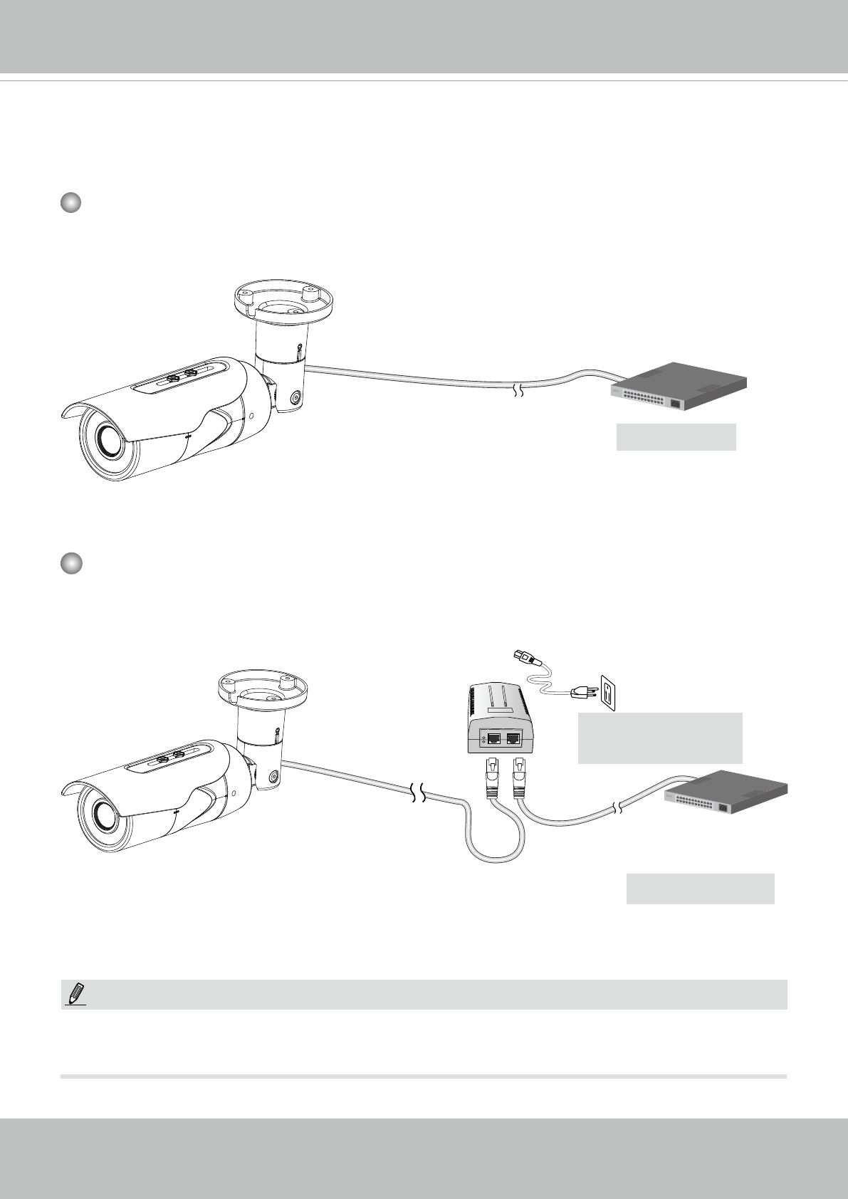
Network Deployment
General Connection (PoE)
When using a PoE-enabled switch
The Network Camera is PoE-compliant, allowing transmission of power and data via a sin-
gle Ethernet cable. Follow the below illustration to connect the Network Camera to a PoE-
enabled switch via Ethernet cable.
When using a non-PoE switch
Use a PoE power injector (optional) to connect between the Network Camera and a non-
PoE switch.
NOTE:
1. The camera is only to be connected to PoE networks without routing to outside plants.
2. For PoE connection, use only UL listed I.T.E. with PoE output.
PoE Switch
802.3af
Non-PoE Switch
PoE Power Injector
(optional)