Before You Use It is important to carefully examine the contents with the Chapter Package Contents after opening the package. If there is anything missing, contact your reseller. Read the Chapter Physical Description before assembling and operating the device and peripherals. Understanding the physical description can prevent damage caused by abnormal usage and reduce most problems during installation.
Table of Contents Before You Use .......................................................1 Table of Contents ...................................................2 Package Contents...................................................4 Features and Benefits.............................................5 Physical Description ...............................................7 Front Panel ......................................................................7 Rear Panel .................................................
Configure System via FTP ................................................ 42 Telnet Commands ........................................................... 47 Appendix ..............................................................49 A. Troubleshooting .......................................................... 49 B. Frequently Asked Questions.......................................... 49 B. Frequently Asked Questions.......................................... 50 C. Upgrade System Firmware .......................
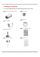
Package Contents If any of the following items are missing, please contact your reseller.
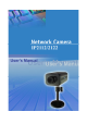
Features and Benefits Network Camera is a high-performance networking video transmitter. With powerful VLIW DSP core and fully optimized algorithm, it can compress and transmit the high quality real-time video through standard TCP/IP inter-network. In addition to meet the basic needs of video feed, many advanced features are added to help building applications of surveillance or web attraction. The state-of-art design well compromises among stable, robust, simple-to-use and flexibility.
security system in your home or office. ☆ Weekly schedule for automatic surveillance The user-defined time period will repeat weekly to check any security settings and accordingly sending notification or drive external devices. It is easy to install in SOHO, retail shop and home as a security system. ☆ Flexible I/O control for external devices There is one opto-isolated sensor input and one relay output to control external devices.
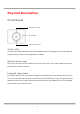
Physical Description Front Panel Manual focus ring Status LED Internal ring screw Status LED The dual color LED indicates system and network status including power-on-self-test and system activity. Refer to the Appendix for details. Manual focus ring The ring of the lens can be rotated to fine tune the focus. The video output at the rear panel can be used to monitor.
Rear Panel BNC video output connector A 75Ohms-resistance video connector can be connected to a TV for monitoring the video from the front CCD sensor. Ethernet 10/100 socket Connect to an Ethernet network with a UTP category 5 cable of length shorter than 100 meters according to the standard. Reset and restore button There is a button hidden in the pinhole beside the Ethernet socket. It is used to reset the system or restore the factory default settings.
Network Camera provides a general I/O terminal block with one digital input and one relay switch for device control. Pin 1 and pin 2 can be connected to an external sensor and the state of voltage will be monitored from the initial state 'LOW'. The relay switch of pin 3 and pin 4 can be used to turn on or off the external device. Power cord socket Connect the power jack of the included power adapter. Connecting the power adapter should be the last operation while physically installing Network Camera.
How to Install To easily fit into various environments, Network Camera automatically detects the attached interfaces and configures itself to the best condition. The high performance built-in CCD and lens always give users delicate image quality. In the following content, "user" refers to those who can access Network Camera and "administrator" means the supervisor who has the root password to configure Network Camera in addition to general access.
Ethernet Environment Hardware installation Before installing multiple Network Cameras at the well-chosen locations, the administrator should memorize the serial numbers on the packages respectively for future use. Cable connection Connect the supplied cables from Network Camera to related devices according to the above diagram. Note that the power adaptor must be kept unplugged until other cables are firmly connected.
Software installation Easy way with installer program In order to configure Network Camera’s remotely, administrators should keep the serial numbers of the new Network Camera’s for identification and initial passwords. After successfully mounting Network Camera’s in the proper position, run the Installer program on the PC in the same network to locate the newly mounted Network Camera’s. Network Camera’s also support manual setup procedures to non-Windows based environments.
click directly on to access the Network Camera in the default browser. If the IP address is taken by another network device in the network, the Installer program will pop out another message window to warn that the assigned IP conflicts. In this case, administrators should ask the network supervisor for a vacant IP address.
Manual way with existing programs For those environments such as MAC, Linux, Unix or other operating systems, whose installer is not yet available, some common network tools including ARP and PING can be used to install Network Camera. Before proceeding further, make sure ARP and PING programs exist. First, type arp –s “assigned IP address” “Ethernet address” to add an entity in the system’s name table.
First access to Network Camera Change initial password of administrator Starting the Web browser to connect to the assigned IP address of Network Camera, users will be asked for user name and password by an authentication message window. A root password, identical to the Network Camera's serial number, is needed for the initial access to a newly installed Network Camera. The administrator must change the root password immediately after the initial installation to ensure security.
How to Use Open your familiar web browser and connect to Network Camera just like any general web site and the video will present on demand. Make sure the web address of the target Network Camera is accurate. Authentication After opening the Web browser and typing in the URL of Network Camera, a dialogue window will pop out to request a username and password. For administrator’s initial usage of Network Camera, enter the username as “root” and the password as the serial number in capital letters.
Installing Plug-in If it is initial access to Network Camera via the Web browser supporting server push, the motioned pictures will display directly. If the Web browser is Internet Explorer in Windows, users will be asked to install a new plug-in that is provided by Network Camera. This plug-in has been registered for certificate and is used to display motioned pictures in the Internet Explorer. Users may click on to install the plug-in.
Main Page Basic functions are displayed in main entrance page of Network Camera. The first figure below is graphic mode that has better visual effect and the second one is text mode that will shorten download time. The main page may look different depending on the PT scanner or the privilege of the user.
Text mode Text mode is default if any image button is not available. Network Camera Video quality selection It allows users to adjust the video quality for speed or smoothness. The performance is also subject to the network bandwidth and the number of users. Five options are available to be chosen from “Medium” to “Excellent”.
“Standard×2” and “Double”. “Half×2” consumes the same bandwidth as “Half” but has the same size with “Standard”. Of course the visual effect is worse than “Standard”. “Standard×2” compared to “Double” is similar to the case. “Half×2” is especially suits in the low bandwidth environment like a dial-up network. To fit into the small image area, timestamp will be skipped in “Half” and “Half×2” modes.
System Configuration Introduction The system configuration can be easily done remotely on Internet Explorer through the Web interface. There are two wizards in addition to classified categories of system configurations. They can give friendly instructions and facilitate the setup job. Alternately administrators may type directly the URL of system configuration, “http:///setup/config.html”, to directly enter the configuration page.
Setup Wizard The setup wizard will guide administrator to enter necessary information including system name, current date and time, administrator’s password, video configuration and captions, and network settings. Administrators can exit the procedures anytime to reserve the current configuration. Finally the setup wizard will ask for reboot to validate the changes and administrators can decide to reboot later.
Definitions of Configuration System parameters Change host name The “host name” is used for the homepage title of main page and displays as the title over the video window on the main page. The maximum string length is 40 characters or 20 characters in double-byte-character-systems like Chinese or Japanese. Adjust date and time There are three ways to adjust system date and time. The easiest is to make Network Camera "Sync with computer time".
Security privilege Change root password To change the administrator’s password, type the new password in both text boxes identically. What is typed will be displayed as asterisks for security purposes. The maximum password is 16 characters. After pressing , the web browser will ask administrators for the new password for access. Add new users To add a new user, type the new user's name and password, check respective privilege, and then press to insert the entry.
Network settings Fix the IP address To eliminate incautious mistakes during installation, Network Camera will stay in installation mode whenever it starts unless "Reset network at next boot" is disabled. This option can also be disabled using the Installer program. Once the option is disabled, Network Camera will skip installation at the next boot and the Installer program will not find the installed units.
FTP. Even in modem application, Network Camera will send out a connection log whenever it dials out to an ISP or dialup server outside. If the administrator has setup some applications in either event mode or sequential mode, Network Camera will send out snapshots once conditions are met. To activate e-mail function, enter correct settings of "SMTP (mail) server" and "Recipient email address".
Administrators should notice that the basic network settings including IP address, subnet mask, default router and DNS servers will be cleared when the network interface is switched to the other between Ethernet and modem. Video and motion detection Adjust image settings "Time stamp" and "Text on image" will be enclosed in image for reference. The timestamp is captured from date and time of Network Camera that is maintained by an on-board real-time clock.
Application constitution Administrators can use combinations of options on the application page to perform many useful security applications. Network Camera provides two application modes; one is performed according to the settings on the web page, the other is performed according to the external command script. Though most settings will automatically be done by the Application Wizard, administrators still can adjust the settings from this page.
event” option to drive some device attached to the digital output several seconds after the event happens and/or send snapshots that are taken right at the moment. . If administrators want to receive some snapshots to check the event, “Upload snapshot while input condition match” please check the box to get snapshots when inputting condition is matched the setting or check the “Upload snapshots while motion detected” box to get snapshot when motion has been detected.
Homepage layout There are two homepage display modes. One is "Image mode" that uses graphics for links; the other is "Text mode" that mostly uses text for links. Administrators may easily give Network Camera a different presence of homepage. The "logo graph" for the system logo at the upper-left corner can be hidden; or the default image from the system memory can be used; or an external resource can be used by assigning a URL. The "Background graph" is similar.
View log file There is some useful information in the system log including current system configuration and activity history with timestamp for tracking. View parameters The whole system parameters will be categorized listed for administrators to check. The content is the same as CONFIG.INI. Factory default It is used to restore the factory default settings. This means any changes made before will be lost and the system will be reset to the initial status as shipping out of the factory.
Advanced Functions Capture Up-to-date Still Images Get snapshot via URL Administrator and users can use the specific URL to capture the current still image. URL http:///cgi-bin/video1.jpg[?=] param quality size value Description 1 Medium 2 Standard 3 Good 4 Detailed 5 Excellent 1 Half 2 Standard 3 Double Get snapshot via FTP Administrator and users can log-in the FTP daemon of Network Camera to download the refreshed JPEG image named video.jpg.
Video Embedded in Customers’ Homepage In additional to the URL, some scripts should be added to download a plug-in for motion pictures. The following example simply displays title text and a real-time video window in Internet Explorer or Netscape. The user name and password should be configured in advance. Those who are familiar with HTML can easily add more components or rewrite a more vivid and useful homepage.
Download Event-triggered Snapshots There are three video image files for the video channel of three stages: pre-alarm, the moment when triggered and post-alarm. Only the snapshots captured by the last event are preserved. Administrator and users can use FTP or URL to get the saved snapshots. They can also be browsed from the application page in system configuration. Get triggered snapshots via URL /cgi-bin/snapshot.
Uploading Snapshots Periodically Upload snapshots to external FTP server In sequential mode, Network Camera will send out snapshots according to interval and period settings. If snapshot files are intended for quick updates, it is better to skip date and time suffix. The file name will then be video.jpg. If the snapshots are used for occasional monitoring, suffix with date and time can help administrators classify them easily.
Customize Graphics in Homepage While in text mode, there is a small icon named BTN_TEXT.GIF preceding with each link that can be changed by administrators. While in image mode, the default method will use the image stored in Flash memory. The followings are the referenced file name and size limitation of each stored images. Administrators may customize preferred image under the size limit and put to the specific name via FTP. Administrators can download the original images before upload for backup.
Command Script for Complex Applications Besides the application wizard, Network Camera provides a more professional command script for advanced applications. The command script will be executed exclusively with the settings in Application page of system configuration except for the weekly schedule. To build the advanced application, follow the steps below. 1. Use any text editor to edit the appropriate command script according to the command format. The script size cannot exceed 500 bytes. 2.
“Digital input state”: H (high), L (low), / (low to high), \ (high to low) “M”: motion detection event.
Practical examples Command line Description M1=1C; When any motion is detected, “Normal Close” of relay output will short with “Common”. 1\=(5)1O; When DI transients from high to low, “Normal Open” of relay output will short with COMMON in 5 seconds. A\=W{192.168.0.1 If there is no video signal, a message “no signal!” will be sent to :6000}{no port 6000 of 192.168.0.1 once. signal!}; 1H=V1P15; When sensor input 2 is high, drive the camera mapped to video 1 to go to preset location 16.
URL for External Device Control Query status of digital input /cgi-bin/getdi.cgi Network Camera will return the status of digital input. Drive digital output /cgi-bin/setdo.cgi?do1= : C, O denoting Normal Close or Normal Open respectively.
URL of System Maintenance Download System Log via FTP Besides viewing the system log from the web page, administrators can download the system log file, SYSTEM.LOG, via FTP. To log into the FTP daemon, enter “root” as the user name and the same administrator’s password used in Web access. Restart System via URL /cgi-bin/reset.cgi Restart Network Camera without warning. Restore Factory Default Settings via URL /cgi-bin/restore.
Configure System via FTP Administrators can use FTP to configure Network Camera much quicker than Web page especially for multiple targets. To configure system via FTP, first download the parameter file, CONFIG.INI, to customize each field according to the environment and then upload back to validate the new settings. To log into the FTP daemon, enter “root” as the user name and the same password used when connecting to the Web server.
(7) (8) (9) (10) (11) (12) (13) (14) (15) (16) (17) (18) (19) (20) (0)0002D1040011 (1) (2) (3) (4) (5) (6) (7) (8) (9) (10) (11) (12) (13) (14) (15) (16) (17) (18) (19) (20) NO 0 string of maximum 16 characters the followings are as same as the above or YES to enable snapshot mode seconds of snapshot interval [LAYOUT] 1 1 0 1 1 http://
string of maximum 8 characters [NETWORK] YES NO 00-02-D1-04-00-11 192.168.0.207 255.255.255.0 0.0.0.0 0.0.0.0 0.0.0.
string of maximum 40 characters NO 80 0 or YES or 1024 ~ 65535 or 64000, 128000, 256000, 512000, 768000, 1000000, 1500000, 2000000 [VIDEO] NO or YES YES or NO
90 1~99 5 1
Telnet Commands Network Camera has a Telnet daemon for only administrators to access some seldom used functions. Using any general terminal program to connect to Network Camera will prompt the user for a password. Username is not requested here since only administrators can access the Telnet daemon. The password is as same as that used in web access. After logging in, type "help" for the command list. If "debug" or "dinote" is not executed, Telnet will disconnect automatically after being idle for 1 minute.
Erase snapshots stored in Flash memory Typing "erase image" will clear all snapshots saved in Flash memory. Erase logo and graphic buttons Typing "erase graph" will clear all images used on the homepage. If no new images are uploaded, the system will switch to text mode and use default images instead. Skip installation at next boot Typing "lock" will inform Network Camera to fix current network settings. It need not wait for installation during the next boot.
Appendix A. Troubleshooting Status LED After the power has been turned on, Network Camera will perform a self-diagnostic to detect any hardware defects. The following table lists the LED patterns in general conditions. In case of any fatal error, the LED will blink in another pattern.
B. Frequently Asked Questions Q Why can’t I see the Network Camera in the installer after reboot? A The installer is only used to install the IP address of Network Camera. If the IP address is fixed by checking the option in the installer, the Network Camera will no longer appear in the installer. Q Why can’t I connect the Network Camera after reboot? A If the IP address is not fixed, Network Camera will always wait for installing command for a valid IP address.
Q How can I use a name instead of the IP address to connect Network Camera? A To allow users to connect to Network Camera through an easily memorized name, the administrators must first configure the name server in his network. Here is an example: the administrator installs the Network Camera with a reserved IP address and assigns it with a name in the domain name service, then users can connect to Network Camera by typing a name instead of IP address.
2. bandwidth share, 3. number of users, 4. number of video input is accessed at one time, 5. the complicated objects in view results in larger image file, 6. the level of your PC or notebook which is responsible of displaying images. In general, the transfer rate in general local network environment can achieve over 200 kilobytes per second and approximately 10 to 20 pictures of normal environment per second. The general frame size is illustrated in the follow table for reference.
‘Input is Rising’ and ‘Input is Falling’ rather than ‘Input is High’ and ‘Input is Low’ to let the condition be triggered only when state is changed. Q The image is not clear enough. Is anything broken? A The lens can be fine adjusted by rotating the outer ring. Please rotate it clockwise or counter-clockwise to focus near or far.
C. Upgrade System Firmware Customers can frequently check the appropriate product folder on our web site to download the latest firmware. Only administrators can upgrade the system firmware of Network Camera. Easy way via Upgrade Wizard Run the Upgrade Wizard included in the product CDROM and proceed by the prompts. Refer to the user's guide of Upgrade Wizard for details. Alternative via FTP 1. Decompress the compressed file in a local folder. A file named FLASH.BIN should appear. 2.
D. URL Commands of Network Camera For some customers who already have their own web site or web control application, Network Camera can be easily integrated through convenient URL. This section lists the commands in URL format corresponding to the basic functions of Network Camera. Some RFC standards related to HTML may be a good reference for implementation of the customized homepage. Page URL The configuration page has a frame layout including option list frame and an option page frame.
Resource name Referenced URL system logo image /logo.gif background image /back.gif button image for configuration /btn_conf.gif icon image for link indicator /btn_text.
General format of command URL Every configuration can be set through URL with POST method by administrators only. URL[?[name=value][&name=value]……] POST root System configuration URL URL: /cgi-bin/system.
characters> slow Snapshot mode open enable demo account demoioallowed allow demo user to control the I/O access slow snapshot mode delay refresh time in snapshot mode Network configuration URL URL: /cgi-bin/network.
returnmail ftp1 primary FTP server ftprp1 ftpuser1 ftppass1 ftpfolder1 ftp2 secondary FTP server ftprp2
Excellent highest resolution 60
Image quality configuration URL URL: NAME /cgi-bin/imagesetting.cgi VALUE DESCRIPTION brightness <-5 ~ 5> adjust brightness of image contrast <-5 ~ 5> adjust contrast of image hue <-5 ~ 5> adjust hue of image saturation <-5 ~ 5> adjust saturation of image preview not save the parameters restore recall the original settings save save the parameters Motion detection configuration URL URL: /cgi-bin/motion.
dirise Enable DI is rising difall Enable DI is falling delay delay time of DO after event ioalarm trigger DO when DI condition matched mdalarm trigger DO when motion detected ioupload upload snapshot when DI condition matched mdupload upload snapshot when motion detected resetdo Clear the DO status smode sequential mode application sinter t
Homepage layout configuration URL URL: /cgi-bin/layout.
E. Time Zone Table While setting the time zone in automatic date/time synchronization, find the hour offset in the followings for your region. GMT stands for Greenwich Mean Time, which is the global time that all time zones are measured from.
(GMT+01:00) West Central Africa (GMT+02:00) Athens, Istanbul, Minsk (GMT+02:00) Bucharest (GMT+02:00) Cairo (GMT+02:00) Harare, Pretoria (GMT+02:00) Helsinki, Kyiv, Riga, Sofia, Tallinn, Vilnius (GMT+02:00) Jerusalem (GMT+03:00) Baghdad (GMT+03:00) Kuwait, Riyadh (GMT+03:00) Moscow, St.
(GMT+10:00) Hobart (GMT+10:00) Vladivostok (GMT+11:00) Magadan, Solomon Is., New Caledonia (GMT+12:00) Auckland, Wellington (GMT+12:00) Fiji, Kamchatka, Marshall Is..
G.
Electromagnetic Compatibility (EMC) USA - This equipment has been tested and found to comply with the limits for a Class B digital device, pursuant to Part 15 of the FCC Rules. These limits are designed to provide reasonable protection against harmful interference in a residential installation. This equipment generates, uses and can radiate radio frequency energy and, if not installed and used in accordance with the instructions, may cause harmful interference to radio communications.