
Specifications


VIVOTEK
User's Manual - 5
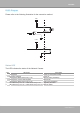
DI/DO Diagram
Please refer to the following illustration for the connection method�
12V
+12V
Digital output
PIN 1
Power+12V
PIN 2
Digital input
PIN 3
Ground
PIN 4
Status LED
The LED indicates the status of the Network Camera�
Item LED status Description
1
Steady Red Power on and system booting
Red LED unlighted Power off
2
Steady Red + Blink Green every 1 sec� Network works (heartbeat)
Steady Red + Green LED unlighted Network fail
3 Steady Red + Blink Green every 2 sec� Audio mute (heartbeat)
4 Blink Red every 0�15 sec� + Blink Green every 1 sec� Upgrading Firmware
5 Blink Red every 0�15 sec� + Blink Green every 0�15 sec� Restore default