Outdoor H.264 Day/Night Weather-proof Quick Installation Guide English ᖅϛ ᙏϛ Рҏᇭ Français Español Deutsch Português Italiano Türkçe Polski Русский Česky Svenska IP8330 Supreme Night Visibility 60 fps @ VGA IP8332 Megapixel This guide describes the basic functions of IP8330 / IP8332. All detailed information is described in the user's manual.
English Warning Before Installation Power off the Network Camera as soon as smoke or unusual odors are detected. Refer to your user's manual for the operating temperature. Contact your distributor in the event of occurrence. Do not place the Network Camera on unsteady surfaces. Do not touch the Network Camera during a lightning storm. Do not insert sharp or tiny objects into the Network Camera. Do not drop the Network Camera.
1 Package Contents IP8330 / IP8332 Waterproof Connector (3 holes, for backup use) Silica Gel Camera Stand Silica gel Power Adapter RJ45 Female/Female Coupler Quick Installation Guide / Warranty Card Software CD 510000202G EN-2
English 2 Physical Description Front Panel IR LED Lens Light Sensor Inner View Reset Button MicroSD/SDHC Card Slot Connectors General I/O Terminal Block Ethernet 10/100 RJ45 Plug Power Cord Socket (black) EN-3
3 Hardware Installation 1. Loose the waterproof connector, then remove the rubber. 2. Loose the back cover. 3. Tear down the aluminum foil vacuum bag and take out the silica gel. Attach the supplied silica gel to the inner side of the Network Camera. (Please replace the silica gel with a new one if you open the back cover after installation.) 4. Make sure all cable lines are securely connected. 5. Tighten the back cover, rubber and waterproof connector. 6.
English 4 Network Deployment General Connection (without PoE) 1. If you have external devices such as sensors and alarms, make the connection from general I/O terminal block. GND DI AC24V AC24V GND : Ground DI : Digital Input AC24V: 24V AC24V: 24V 2. Use the supplied RJ45 female/female coupler to connect the Network Camera to a switch. Use Category 5 Cross Cable when Network Camera is directly connected to PC. POWER LINK COLLISION 1 2 3 4 5 RECEIVE PARTITION 3.
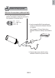
Power over Ethernet (PoE) When using a PoE-enabled switch The Network Camera is PoE-compliant, allowing transmission of power and data via a single Ethernet cable. Follow the below illustration to connect the Network Camera to a PoE-enabled switch via Ethernet cable. POWER COLLISION 1 2 3 4 5 LINK RECEIVE PARTITION PoE Switch When using a non-PoE switch Use a PoE power injector (optional) to connect between the Network Camera and a non-PoE switch.
English 5 Assigning an IP Address 1. Install “Installation Wizard 2” from the Software Utility directory on the software CD. 2. The program will conduct an analysis of your network environment. After your network is analyzed, please click on the “Next” button to continue the program. IW2 Installation Wizard 2 3. The program will search for all VIVOTEK Video Receivers, Video Servers, and Network Cameras on the same LAN. 4. After searching, the main installer window will pop up.
6 Ready to Use 1. Access the Network Camera from the LAN. 2. Retrieve live video through web browsers or recording software. 2010/03/12 14:53:02 For further setup, please refer to the user’s manual on the software CD.
720p HD WDR Pro IP67 Quick Installation Guide English 繁中 簡中 日本語 Français Español Deutsch Português Italiano Türkçe Polski Русский Česky Svenska IP8335H This guide describes the basic functions of IP8335H. More details can be found in the User Manual. Copyright New Taipei City P/N: 625015800G Ver.1.0 2011 VIVOTEK INC. All right reserved.