Network Camera IP8330/8332 Bullet User’s Manual IP8330: Supreme Night Visibility • 60 fps @ VGA IP8332: Megapixel IP8330 IP8332 Rev. 1.
VIVOTEK Table of Contents Overview ������������������������������������������������������������������������������������������������������������������������������������������������������3 Read Before Use �������������������������������������������������������������������������������������������������������������������������������������3 Package Contents �����������������������������������������������������������������������������������������������������������������������������������3 Revision History ������
VIVOTEK Overview Read Before Use The use of surveillance devices may be prohibited by law in your country. The Network Camera is not only a high-performance web-ready camera but can also be part of a flexible surveillance system. It is the user’s responsibility to ensure that the operation of such devices is legal before installing this unit for its intended use. It is important to first verify that all contents received are complete according to the Package Contents listed below.
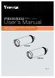
VIVOTEK Physical Description Front Panel Lens IR LED Light Sensor Back Panel Reset Button SD/SDHC Card Slot Connectors General I/O Terminal Block Ethernet 10/100 RJ45 Plug Power Cord Socket (black) 4 - User's Manual
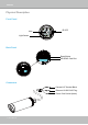
VIVOTEK General I/O Terminal Block This Network Camera provides a general I/O terminal block which is used to connect external input devices. The pin definitions are described below. GND DI AC24V AC24V Pin GND DI AC24V AC24V Name Ground Digital Iutput 24V 24V DI Diagram Please refer to the following illustration for the connection method. +12V PIN 2 Digital input PIN 1 Ground MicroSD/SDHC Card Capacity This network camera is compliant with MicroSD/SDHC 32GB and other preceding standard SD cards.
VIVOTEK Hardware Reset Reset Button The reset button is used to reset the system or restore the factory default settings. Sometimes resetting the system can return the camera to normal operation. If the system problems remain after reset, restore the factory settings and install again. Reset: Press and release the recessed reset button with a paper clip or thin object. Wait for the Network Camera to reboot. Restore: Press and hold the recessed reset button until the status LED rapidly blinks.
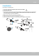
VIVOTEK Installation Hardware Installation 1. Loose the waterproof connector, then remove the rubber. 2. Loose the back cover. 3. Tear down the aluminum foil vacuum bag and take out the silica gel. Attach the supplied silica gel to the inner side of the Network Camera. (Please replace the silica gel with a new one if you open the back cover after installation.) 4. Make sure all cable lines are securely connected. 5. Tighten the back cover, rubber and waterproof connector. 6.
VIVOTEK IMPORTANT! 1. T he camera comes with an angled cut sunshield. If you install the camera in a ceiling-mount orientation, you will need to change the sunshield's orientation. To adjust the sunshield, 1-1. Loosen the sunshield seal ring using an included acrylic opener. 1-2. You do not need to remove the sunshield. Rotate the protruding ridge to the desired direction from which sunlight can cause glare. 1-3.
VIVOTEK Network Deployment Setting up the Network Camera over the Internet This section explains how to configure the Network Camera to an Internet connection. 1. If you have external devices such as sensors and alarms, make the connection from the general I/O terminal block. 2. Use the supplied RJ45 female/female coupler to connect the Network Camera to a switch. Use a Category 5 Cross Cable when Network Camera is directly connected to PC. 3.
VIVOTEK WAN (Wide Area Network ) Internet Router IP address : from ISP POWER COLLISION 1 2 3 4 5 IP address : 192.168.0.3 Subnet mask : 255.255.255.0 Default router : 192.168.0.1 LINK RECEIVE PARTITION LAN (Local Area Network) Router IP address : 192.168.0.1 Cable or DSL Modem IP address : 192.168.0.2 Subnet mask : 255.255.255.0 Default router : 192.168.0.1 2. In this case, if the Local Area Network (LAN) IP address of your Network Camera is 192.168.0.
VIVOTEK Set up the Network Camera through Power over Ethernet (PoE) When using a PoE-enabled switch The Network Camera is PoE-compliant, allowing transmission of power and data via a single Ethernet cable. Follow the below illustration to connect the Network Camera to a PoE-enabled switch via Ethernet cable.
VIVOTEK Software Installation Installation Wizard 2 (IW2), free-bundled software included on the product CD, helps you set up your Network Camera on the LAN. 1. Install IW2 under the Software Utility directory from the software CD. Double click the IW2 shortcut on your desktop to launch the program. 2. The program will conduct an analysis of your network environment. After your network environment is analyzed, please click Next to continue the program. 3.
VIVOTEK Ready to Use 1. Access the Network Camera on the LAN. 2. Retrieve live video through a web browser or recording software.
VIVOTEK Accessing the Network Camera This chapter explains how to access the Network Camera through web browsers, RTSP players, 3GPP-compatible mobile devices, and VIVOTEK recording software. Using Web Browsers Use Installation Wizard 2 (IW2) to access to the Network Cameras on the LAN. If your network environment is not a LAN, follow these steps to access the Network Camera: 1. Launch your web browser (ex. Microsoft® Internet Explorer, Mozilla Firefox, or Netscape). 2.
VIVOTEK ► By default, the Network Camera is not password-protected. To prevent unauthorized access, it is highly recommended to set a password for the Network Camera. For more information about how to enable password protection, please refer to Security on page 27. ► If you see a dialog box indicating that your security settings prohibit running ActiveX ® Controls, please enable the ActiveX ® Controls for your browser. 1. Choose Tools > Internet Options > Security > Custom Level. 2.
VIVOTEK Using RTSP Players To view the MPEG-4 streaming media using RTSP players, you can use one of the following players that support RTSP streaming. Quick Time Player Real Player VLC media player 1. Launch the RTSP player. mpegable Player 2. Choose File > Open URL. A URL dialog box will pop up. 3.
VIVOTEK Using 3GPP-compatible Mobile Devices To view the streaming media through 3GPP-compatible mobile devices, make sure the Network Camera can be accessed over the Internet. For more information on how to set up the Network Camera over the Internet, please refer to Setup the Network Camera over the Internet on page 9. To utilize this feature, please check the following settings on your Network Camera: 1.
VIVOTEK Using VIVOTEK Recording Software The product software CD also contains recording software, allowing simultaneous monitoring and video recording for multiple Network Cameras. Please install the recording software; then launch the program to add the Network Camera to the Channel list. For detailed information about how to use the recording software, please refer to the user’s manual of the software or download it from http://www.vivotek.com.
VIVOTEK Main Page This chapter explains the layout of the main page. It is composed of the following sections: VIVOTEK INC. Logo, Host Name, Camera Control Area, Configuration Area, Menu, and Live Video Window. VIVOTEK INC. Logo Host Name Camera Control Area Configuration Area Live View Window VIVOTEK INC. Logo Click this logo to visit the VIVOTEK website. Host Name The host name can be customized to fit your needs. For more information, please refer to System on page 25.
VIVOTEK Live Video Window ■ The following window is displayed when the video mode is set to H.264 / MPEG-4: MPEG-4 Protocol and Media Options Video Title Title and Time 2010/01/13 13:44:17 Time Video 13:44:17 2010/01/13 Video Control Buttons Video Title: The video title can be configured. For more information, please refer to Video Settings on page 53. H.264 / MPEG-4 Protocol and Media Options: The transmission protocol and media options for H.264 / MPEG-4 video streaming.
VIVOTEK Full Screen: Click this button to switch to full screen mode. Press the “Esc” key to switch back to normal mode. ■ The following window is displayed when the video mode is set to MJPEG: Video Title Title and Time 2010/01/13 13:44:17 Time Video 13:44:17 2010/01/13 Video Control Buttons Video Title: The video title can be configured. For more information, please refer to Video Settings on page 53. Time: Display the current time. For more information, please refer to Video Settings on page 53.
VIVOTEK Client Settings This chapter explains how to select the stream transmission mode and saving options on the local computer. When completed with the settings on this page, click Save on the page bottom to enable the settings. H.264 / MPEG-4 Protocol Options H.264/MPEG-4 Protocol Options Depending on your network environment, there are four transmission modes of H.264 or MPEG-4 streaming: UDP unicast: This protocol allows for more real-time audio and video streams.
VIVOTEK MP4 Saving Options Users can record live video as they are watching it by clicking page. Here, you can specify the storage destination and file name. Start MP4 Recording on the main Folder: Specify a storage destination for the recorded video files. File name prefix: Enter the text that will be appended to the front of the video file name. Add date and time suffix to the file name: Select this option to append the date and time to the end of the file name.
VIVOTEK Configuration Click Configuration on the main page to enter the camera setting pages. Note that only Administrators can access the configuration page. VIVOTEK offers an easy-to-use user interface that helps you set up your network camera with minimal effort. To simplify the setting procedure, two types of user interfaces are available: Advanced Mode for professional users and Basic Mode for entry-level users.
VIVOTEK Advanced Mode Configuration List Click to switch to Basic Mode Firmware Version Each function on the configuration list will be explained in the following sections. Those functions that are displayed only in Advanced Mode are marked with Advanced Mode . If you want to set up advanced functions, please click [Advanced Mode] on the bottom of the configuration list to quickly switch over.
VIVOTEK System Time Keep current date and time: Select this option to preserve the current date and time of the Network Camera. The Network Camera’s internal real-time clock maintains the date and time even when the power of the system is turned off. Synchronize with computer time: Select this option to synchronize the date and time of the Network Camera with the local computer. The read-only date and time of the PC is displayed as updated. Manual: The administrator can enter the date and time manually.
VIVOTEK Security This section explains how to enable password protection and create multiple accounts. Root Password The administrator account name is “root”, which is permanent and can not be deleted. If you want to add more accounts in the Manage User column, please apply the password for the “root” account first. 1. Type the password identically in both text boxes, then click Save to enable password protection. 2.
VIVOTEK HTTPS (Hypertext Transfer Protocol over SSL) Advanced Mode This section explains how to enable authentication and encrypted communication over SSL (Secure Socket Layer). It helps protect streaming data transmission over the Internet on higher security level. Enable HTTPS Check this item to enable HTTPS communication, then select a connection option: "HTTP & HTTPS" or "HTTPS only". Note that you have to create and install a certificate first in the second column before clicking the Save button.
VIVOTEK 4. The Certificate Information will automatically be displayed in the third column as shown below. You can click Property to view detailed information about the certificate. 5. Click Home to return to the main page. Change the address from “http://” to “https://“ in the address bar and press Enter on your keyboard. Some Security Alert dialogs will pop up. Click OK or Yes to enable HTTPS. https:// https://192.168.5.151/index.
VIVOTEK Create self-signed certificate manually 1. Select this option. 2. Click Create to open the Create Certificate page, then click Save to generate the certificate. 3. The Certificate Information will automatically be displayed in the third column as shown below. You can click Property to see detailed information about the certificate. Create certificate and install : Select this option if you want to create a certificate from a certificate authority. 1. Select this option. 2.
VIVOTEK 3. If you see the following Information bar, click OK and click on the Information bar at the top of the page to allow pop-ups. 4. The pop-up window shows an example of a certificate request.
VIVOTEK 5. Look for a trusted certificate authority that issues digital certificates. Enroll the Network Camera. Wait for the certificate authority to issue a SSL certificate; click Browse... to search for the issued certificate, then click Upload in the second column. NOTE ► How do I cancel the HTTPS settings? 1. Uncheck Enable HTTPS secure connection in the first column and click Save; a warning dialog will pop up. 2. Click OK to disable HTTPS. 3.
VIVOTEK SNMP (Simple Network Management Protocol) Advanced Mode This section explains how to use the SNMP on the network camera. The Simple Network Management Protocol is an application layer protocol that facilitates the exchange of management information between network devices. It helps network administrators to remotely manage network devices and find, solve network problems with ease. ■ The SNMP consists of the following three key components: 1.
VIVOTEK Network This section explains how to configure a wired network connection for the Network Camera. Network Type LAN Select this option when the Network Camera is deployed on a local area network (LAN) and is intended to be accessed by local computers. The default setting for the Network Type is LAN. Rememer to click Save when you complete the Network setting.
VIVOTEK Primary DNS: The primary domain name server that translates hostnames into IP addresses. Secondary DNS: Secondary domain name server that backups the Primary DNS. Primary WINS server: The primary WINS server that maintains the database of computer name and IP address. Secondary WINS server: The secondary WINS server that maintains the database of computer name and IP address.
VIVOTEK NOTE ► If the default ports are already used by other devices connected to the same router, the Network Camera will select other ports for the Network Camera. ► If UPnP TM is not supported by your router, you will see the following message: Error: Router does not support UPnP port forwarding. ► Steps to enable the UPnP TM user interface on your computer: Note that you must log on to the computer as a system administrator to install the UPnP TM components. 1.
VIVOTEK 4. In the Networking Services dialog box, select Universal Plug and Play and click OK. 5. Click Next in the following window. 6. Click Finish. UPnP TM is enabled. ► How does UPnP TM work? UPnP TM networking technology provides automatic IP configuration and dynamic discovery of devices added to a network. Services and capabilities offered by networked devices, such as printing and file sharing, are available among each other without the need for cumbersome network configuration.
VIVOTEK Enable IPv6 Select this option and click Save to enable IPv6 settings. Please note that this only works if your network environment and hardware equipment support IPv6. The browser should be Microsoft® Internet Explorer 6.5, Mozilla Firefox 3.0 or above. When IPv6 is enabled, by default, the network camera will listen to router advertisements and be assigned with a link-local IPv6 address accordingly. IPv6 Information: Click this button to obtain the IPv6 information as shown below.
VIVOTEK Please follow the steps below to link to an IPv6 address: 1. Open your web browser. 2. Enter the link-global or link-local IPv6 address in the address bar of your web browser. 3. The format should be: http://[2001:0c08:2500:0002:0202:d1ff:fe04:65f4]/ IPv6 address 4. Press Enter on the keyboard or click Refresh button to refresh the webpage.
VIVOTEK IEEE 802.1x Advanced Mode Enable this function if your network environment uses IEEE 802.1x, which is a port-based network access control. The network devices, intermediary switch/access point/hub, and RADIUS server must support and enable 802.1x settings. The 802.1x standard is designed to enhance the security of local area networks, which provides authentication to network devices (clients) attached to a network port (wired or wireless).
VIVOTEK 3. When all settings are complete, move the Network Camera to the protected LAN by connecting it to an 802.1x enabled switch. The devices will then start the authentication automatically. NOTE ► The authentication process for 802.1x: 1. The Certificate Authority (CA) provides the required signed certificates to the Network Camera (the supplicant) and the RADIUS Server (the authentication server). 2. A Network Camera requests access to the protected LAN using 802.
VIVOTEK QoS (Quality of Service) Advanced Mode Quality of Service refers to a resource reservation control mechanism, which guarantees a certain quality to different services on the network. Quality of service guarantees are important if the network capacity is insufficient, especially for real-time streaming multimedia applications. Quality can be defined as, for instance, a maintained level of bit rate, low latency, no packet dropping, etc.
VIVOTEK QoS/DSCP (the DiffServ model) DSCP-ECN defines QoS at Layer 3 (Network Layer). The Differentiated Services (DiffServ) model is based on packet marking and router queuing disciplines. The marking is done by adding a field to the IP header, called the DSCP (Differentiated Services Codepoint). This is a 6-bit field that provides 64 different class IDs. It gives an indication of how a given packet is to be forwarded, known as the Per Hop Behavior (PHB).
VIVOTEK HTTP Advanced Mode To utilize HTTP authentication, make sure that your have set a password for the Network Camera first; please refer to Security on page 27 for details. Authentication: Depending on your network security requirements, the Network Camera provides two types of security settings for an HTTP transaction: basic and digest. If basic authentication is selected, the password is sent in plain text format and there can be potential risks of being intercepted.
VIVOTEK URL command -- http://:/ For example, when the Access name for stream 2 is set to video2.mjpg: 1. Launch Mozilla Firefox or Netscape. 2. Type the above URL command in the address bar. Press Enter. 3. The JPEG images will be displayed in your web browser. http://192.168.5.151/video2.
VIVOTEK RTSP Streaming To utilize RTSP streaming authentication, make sure that you have set a password for the Network Camera first; please refer to Security on page 27 for details. Authentication: Depending on your network security requirements, the Network Camera provides three types of security settings for streaming via RTSP protocol: disable, basic, and digest. If basic authentication is selected, the password is sent in plain text format, but there can be potential risks of it being intercepted.
VIVOTEK RTSP port /RTP port for video/ RTCP port for video ■ RTSP (Real-Time Streaming Protocol) controls the delivery of streaming media. By default, the port number is set to 554. ■ The RTP (Real-time Transport Protocol) is used to deliver video data to the clients. By default, the RTP port for video is set to 5556. ■ The RTCP (Real-time Transport Control Protocol) allows the Network Camera to transmit the data by monitoring the Internet traffic volume. By default, the RTCP port for video is set to 5557.
VIVOTEK DDNS This section explains how to configure the dynamic domain name service for the Network Camera. DDNS is a service that allows your Network Camera, especially when assigned with a dynamic IP address, to have a fixed host and domain name. DDNS: Dynamic domain name service Enable DDNS: Select this option to enable the DDNS setting. Provider: Select a DDNS provider from the provider drop-down list. VIVOTEK offers Safe100.net, a free dynamic domain name service, to VIVOTEK customers.
VIVOTEK [Register] Successfully Your account information has been mailed to registered e-mail address 4. Select Enable DDNS and click Save to enable the setting. ■ CustomSafe100 VIVOTEK offers documents to establish a CustomSafe100 DDNS server for distributors and system integrators. You can use CustomSafe100 to register a dynamic domain name if your distributor or system integrators offer such services. 1. In the DDNS column, select CustomSafe100 from the drop-down list. 2.
VIVOTEK Access List Advanced Mode This section explains how to control access permission by verifying the client PC’s IP address. General Settings Maximum number of concurrent streaming connection(s) limited to: Simultaneous live viewing for 1~10 clients (including stream 1 ~ stream 5). The default value is 10. If you modify the value and click Save, all current connections will be disconnected and automatically attempt to re-link (IE Explore or Quick Time Player).
VIVOTEK ■ Refresh: Click this button to refresh all current connections. ■ Add to deny list: You can select entries from the Connection Status list and add them to the Deny List to deny access. Please note that those checked connections will only be disconnected temporarily and will automatically try to re-link again (IE Explore or Quick Time Player). If you want to enable the denied list, please check Enable access list filtering and click Save in the first column.
VIVOTEK Network: This rule allows the user to assign a network address and corresponding subnet mask to the Allow/Deny List. For example: IP address 192.168.2.x will be blocked. Range: This rule allows the user to assign a range of IP addresses to the Allow/Deny List. Note: This rule is only applied to IPv4.
VIVOTEK Video This section explains how to configure the video settings of the Network Camera. Video Settings Video title: Enter a name that will be displayed on the title bar of the live video. Video Title Title and Time 2010/01/13 13:44:17 Video 13:44:17 2010/01/13 Color: Select to display color or black/white video streams. Power line frequency: Set the power line frequency consistent with local utility settings to eliminate image flickering associated with fluorescent lights.
VIVOTEK Overlay title and time stamp on video: Select this option to place the video title and time on the video streams. Note that when the frame size is set to 176 x 144 as shown in the picture below, only the time will be stamped on the video streams. 2010/01/13 13:44:17 13:44:17 2010/01/13 Image Settings Advanced Mode Click Image Settings to open the Image Settings page. On this page, you can tune the White balance, Brightness, Saturation, Contrast, and Sharpness settings for the video.
VIVOTEK White balance: Adjust the value for the best color temperature. ■ Auto The Network Camera automatically adjusts the color temperature of the light in response to different light sources. The white balance setting defaults to Auto and works well in most situations. ■ Keep current value Follow the steps below to manually set the white balance to compensate for the ambient lighting conditions. 1. Set the White balance to Auto and click Save. 2.
VIVOTEK NOTE ► Up to 5 privacy mask windows can be set up on the same screen. ► If you want to delete the privacy mask window, please click the ‘x’ on the upper right-hand corner of the window. Sensor Settings Advanced Mode Click Sensor Settings to open the Sensor Settings page. On this page, you can set the maximum exposure time, exposure level, and AGC (Auto Gain Control) settings.
VIVOTEK ■ Enable BLC (Back Light Compensation): Enable this option when the object is too dark or too bright to recognize. It allows the camera to adjust to the best light conditions in any environment and automatically give the necessary light compensation. You can click Preview to fine-tune the image, or click Restore to recall the original settings without incorporating the changes. When completed with the settings on this page, click Save to enable the settings and click Close to exit the page.
VIVOTEK Viewing Window Advanced Mode Note: This function in only for IP8332 (megapixel model). Click Viewing Window to open the Viewing Window Settings page. The IP8332 supports multiple streams with frame size ranging from 176 x 144 to 1280 x 800. The definition of multiple streams: ■ Stream 1: Users can define the "Region of Interest" (viewing region) and the "Output Frame Rate" (size of the live view window).
VIVOTEK ■ The parameters of the multiple streams: Stream 1 Stream 2 Stream 3 Stream 4 Region of Interest Output frame size 1280 X 800 ~ 176 x 144 (Selectable) 1280 X 800 ~ 176 x 144 (Selectable) 1280 X 800 ~ 176 x 144 (Selectable) 1280 X 800 (Fixed) 1280 X 800 ~ 176 x 144 (Selectable) 1280 X 800 ~ 176 x 144 (Selectable) 1280 X 800 ~ 176 x 144 (Selectable) 1280 X 800 ~ 176 x 144 (Selectable) When completed with the settings in the Viewing Window, click Save to enable the settings and click Close to exi
VIVOTEK If H.264 / MPEG-4 mode is selected, the video is streamed via RTSP protocol. There are four parameters for you to adjust the video performance: ■ Frame size You can set up different video resolution for different viewing devices. For example, set a smaller frame size and lower bit rate for remote viewing on mobile phones and a larger video size and a higher bit rate for live viewing on web browsers. Note that a larger frame size takes up more bandwidth.
VIVOTEK ■ Intra frame period Determine how often to plant an I frame. The shorter the duration, the more likely you will get better video quality, but at the cost of higher network bandwidth consumption. Select the intra frame period from the following durations: 1/4 second, 1/2 second, 1 second, 2 seconds, 3 seconds, and 4 seconds. ■ Video quality A complex scene generally produces a larger file size, meaning that higher bandwidth will be needed for data transmission.
VIVOTEK Day/Night Settings Switch to B/W in night mode Select this to enable the Network Camera to automatically switch to B/W during night mode. IR cut filter With a removable IR-cut filter, this Network Camera can automatically remove the filter to let IR light into the sensor during low light conditions. ■ Auto mode The Network Camera automatically removes the filter by judging the level of ambient light.
VIVOTEK Motion Detection This section explains how to configure the Network Camera to enable motion detection. A total of three motion detection windows can be configured. 2010/01/13 13:44:17 Motion Detection Setting 1: For normal situations Follow the steps below to enable motion detection: Follow the steps below to enable motion detection: Motion Detection Setting 2: For special situations 1. Click New to add a new motion detection window. 2.
VIVOTEK A green bar indicates that even though motions have been detected, the event has not been triggered because the image variations still fall under the defined threshold. Percentage = 30% If you want to configure other motion detection settings for day/night/schedule mode, please click Profile to open the Motion Detection Profile Settings page as shown below. A total of three motion detection windows can be configured on this page as well.
VIVOTEK NOTE ► How does motion detection work? A C B D There are two motion detection parameters: Sensitivity and Percentage. In the illustration above, frame A and frame B are two sequential images. Pixel differences between the two frames are detected and highlighted in gray (frame C) and will be compared with the sensitivity setting. Sensitivity is a value that expresses the sensitivity to moving objects.
VIVOTEK Camera Tampering Detection This section explains how to set up camera tamper detection. With tamper detection, the camera is capable of detecting incidents such as redirection, blocking or defocusing, or even spray paint. Please follow the steps below to set up the camera tamper detection function: 1. Check Enable camera tampering detection. 2. Enter the tamper trigger duration. (10 sec. ~ 10 min.
VIVOTEK Homepage Layout Advanced Mode This section explains how to set up your own customized homepage layout. Preview This column shows the settings of your hompage layout. You can manually select the background and font colors in Theme Options (the third column on this page). The settings will be displayed automatically in this Preview field. The following shows the homepage using the default settings: ■ Hide Powered by VIVOTEK: If you check this item, it will be removed from the homepage.
VIVOTEK Theme Options Here you can change the color of your homepage layout. There are three types of preset patterns for you to choose from. The new layout will simultaneously appear in the Preview filed. Click Save to enable the settings.
VIVOTEK ■ Follow the steps below to set up the customed homepage: 1. Click Custom on the left column. 2. Click the field where you want to change the color on the right column. Color Selector Custom Pattern 3. The palette window will pop up as shown below. 2 3 1 4 4. Drag the slider bar and click on the left square to select a desired color. 5. The selected color will be displayed in the corresponding fields and in the Preview column. 6. Click Save to enable the settings.
VIVOTEK Application Advanced Mode This section explains how to configure the Network Camera to responds to particular situations (event). A typical application is that when a motion is detected, the Network Camera sends buffered images to an FTP server or e-mail address as notifications. In the illustration on the right, an event can be Action triggered by many sources, such as motion detection Event Trigger or external digital input devices. When an event is ex.
VIVOTEK Event Settings In the Event Settings column, click Add to open the Event Settings page. On this page, you can arrange three elements -- Trigger, Schedule, and Action to set an event. A total of 3 event settings can be configured. Event name: Enter a name for the event setting. Enable this event: Select this option to enable the event setting. Priority: Select the relative importance of this event (High, Normal, or Low). Events with a higher priority setting will be executed first.
VIVOTEK An event is an action initiated by a user-defined trigger source; it is the causal arrangement of the following three elements: Trigger, Event Schedule, and Action. Trigger This is the cause or stimulus which defines when to trigger the Network Camera. The trigger source can be configured to use the Network Camera’s built-in motion detection mechanism or external digital input devices. There are several choices of trigger sources as shown below.
VIVOTEK ■ Camera tampering detection This option allows the Network Camera to trigger when the camera detects that is is being tampered with. To enable this function, you need to configure the Tampering Detection option first. Please refer to page 66 for detailed information. Event Schedule Specify the period for the event. ■ Select the days of the week. ■ Select the recording schedule in 24-hr time format. Action Define the actions to be performed by the Network Camera when a trigger is activated.
VIVOTEK Here is an example of the Event Settings page: When completed, click Save to enable the settings and click Close to exit Event Settings page. The new event settings / server settings / media settings will appear in the event drop-down list on the Application page.
VIVOTEK Here is an example of the Application page with an event setting: When the Event Status is ON, once an event is triggered by motion detection, the Network Camera will automatically send snapshots via e-mail. If you want to stop the event trigger, you can click ON to turn it to OFF status or click Delete to remove the event setting. To remove a server setting from the list, select a server name from the drop-down list and click Delete.
VIVOTEK Server Settings Click Add Server on Event Settings page to open the Server Setting page. On this page, you can specify where the notification messages are sent when a trigger is activated. A total of 5 server settings can be configured. Server name: Enter a name for the server setting. Server Type There are four choices of server types available: Email, FTP, HTTP, and Network storage. Select the item to display the detailed configuration options. You can configure either one or all of them.
VIVOTEK FTP: Select to send the media files to an FTP server when a trigger is activated. ■ Server address: Enter the domain name or IP address of the FTP server. ■ Server port By default, the FTP server port is set to 21. It can also be assigned to another port number between 1025 and 65535. ■ User name: Enter the login name of the FTP account. ■ Password: Enter the password of the FTP account. ■ FTP folder name Enter the folder where the media file will be placed.
VIVOTEK HTTP: Select to send the media files to an HTTP server when a trigger is activated. ■ URL: Enter the URL of the HTTP server. ■ User name: Enter the user name if necessary. ■ Password: Enter the password if necessary. To verify if the HTTP settings are correctly configured, click Test. The result will be shown in a pop-up window as below. If successful, you will receive a test.txt file on the HTTP server. Click Save to enable the settings, then click Close to exit the page.
VIVOTEK Media Settings Click Add Media on the Event Settings page to open the Media Settings page. On this page, you can specify the type of media that will be sent when a trigger is activated. A total of 5 media settings can be configured. Media name: Enter a name for the media setting. Media Type There are three choices of media types available: Snapshot, Video Clip, and System log. Select the item to display the detailed configuration options. You can configure either one or all of them.
VIVOTEK Video clip: Select to send video clips when a trigger is activated. ■ Source: Select a source of video clip. ■ Pre-event recording The Network Camera has a buffer area; it temporarily holds data up to a certain limit. Enter a number to decide the duration of recording before a trigger is activated. Up to 9 seconds can be set. ■ Maximum duration Specify the maximum recording duration in seconds. Up to 10 seconds can be set.
VIVOTEK You can continue to select a server and media type for the event. Please go back to page 66 for detailed information. ■ SD Test: Click to test your SD card. The system will display a message indicating success or failure. If you want to use your SD card for on board storage, please format it before use. Please refer to page 83 for detailed information. ■ Create folders by date, time, and hour automatically: If you check this item, the system will generate folders automatically by date.
VIVOTEK The following is an example of a file destination with video clips: The format is: YYYYMMDD Click to open the directory 20100115 20100116 20100117 Click to delete all recorded data Click to delete selected items Click 20100115 to open the directory: The format is: HH (24r) Click to open the file list for that hour Video Clip_58.mp4 2010/01/15 Video Clip_59.
VIVOTEK Recording Advanced Mode This section explains how to configure the recording settings for the Network Camera. Recording Settings Insert your SD card and click here to test NOTE ► Before setting up this page, please set up the Network Storage on the Server Settings page first. ► Please remember to format your SD card when using for the first time. Please refer to page 86 for detailed information.
VIVOTEK If successful, you will receive a test.txt file on the network storage server. 3. Enter a server name. 4. Click Save to complete the settings and click Close to exit the page. Recording Settings Click Add to open the recording setting page. In this page, you can define the recording source, recording schedule, and recording capacity. A total of 2 recording settings can be configured. Recording name: Enter a name for the recording setting.
VIVOTEK Source: Select the recording source (stream 1 ~ 4). Trigger: Select a trigger source. ■ Schedule: The server will start to record files on the local storage or network storage (NAS). ■ Network fail: Since network fail, the server will start to record files on the local storage (SD card). Recording Schedule: Specify the recording duration. ■ Select the days of the week. ■ Select the recording start and end times in 24-hr time format.
VIVOTEK Local Storage Advanced Mode This section explains how to manage the SD card for on board storage. Here you can view SD card status, search for recorded files to playback, download, etc. no SD card SD Card Management SD card status: This column shows the status and reserved space of your SD card. Please remember to format the SD card when using for the first time.
VIVOTEK SD card control ■ Enable cyclic storage: Check this item if you want to enable cyclic recording. When the maximum capacity is reached, the oldest file will be overwritten by the latest one. ■ Enable automatic disk cleanup: Check this item and enter the number of days you wish to retain a file. For example, if you enter “7 days”, the recorded files will be stored on the SD card for 7 days. Click Save to enable your settings.
VIVOTEK Search Results The following is an example of search results. There are four columns: Trigger time, Media type, Trigger type, and Locked. Click to sort the search results in either direction. Enter a key word to filter the Numbers of entries displayed on one page search results Highlight an item Click to switch pages View: Click on a search result which will highlight the selected item in purple as shown above. Click the View button and a media window will pop up to play back the selected file.
VIVOTEK Download: Click on a search result to highlight the selected item in purple as shown above. Then click the Download button and a file download window will pop up for you to save the file. JPEGs to AVI: This functions only applies to “JPEG“ format files such as snapshots. You can select several snapshots from the list, then click this button. Those snapshots will be converted into an AVI file. Lock/Unlock: Select the desired search results, then click this button.
VIVOTEK System Log Advanced Mode This section explains how to configure the Network Camera to send the system log to the remote server as backup. Remote Log You can configure the Network Camera to send the system log file to a remote server as a log backup. Before utilizing this feature, it is suggested that the user install a log-recording tool to receive system log messages from the Network Camera. An example is Kiwi Syslog Daemon. Visit http://www.kiwisyslog. com/kiwi-syslog-daemon-overview/.
VIVOTEK View Parameters Advanced Mode The View Parameters page lists the entire system’s parameters in alphabetical order. If you need technical assistance, please provide the information listed on this page.
VIVOTEK Maintenance This chapter explains how to restore the Network Camera to factory default, upgrade firmware version, etc. Reboot This feature allows you to reboot the Network Camera, which takes about one minute to complete. When completed, the live video page will be displayed in your browser. The following message will be displayed during the reboot process. If the connection fails after rebooting, manually enter the IP address of the Network Camera in the address field to resume the connection.
VIVOTEK Export / Upload Files Advanced Mode This feature allows you to Export / Upload daylight saving time rules, custom language files, and setting backup files. Export daylight saving time configuration file: Click to set the start and end time of DST. Follow the steps below to export: 1. In the Export files column, click Export to export the daylight saving time configuration file from the Network Camera. 2. A file download dialog will pop up as shown below.
VIVOTEK Upload daylight saving time rule: Click Browse… and specify the XML file to upload. If the incorrect date and time are assigned, you will see the following warning message when uploading the file to the Network Camera. The following message is displayed when attempting to upload an incorrect file format. Export language file: Click to export language strings. VIVOTEK provides nine languages: English, Deutsch, Español, Français, Italiano, 日本語 , Português, 簡体中文 , and 繁體中文 .
VIVOTEK The following message is displayed when the upgrade has succeeded. Reboot system now!! This connection will close. The following message is displayed when you have selected an incorrect firmware file. Starting firmware upgrade... Do not power down the server during the upgrade. The server will restart automatically after the upgrade is completed. This will take about 1 - 5 minutes.
VIVOTEK Appendix URL Commands for the Network Camera Overview For some customers who already have their own web site or web control application, the Network Camera/Video Server can be easily integrated through URL syntax. This section specifies the external HTTP-based application programming interface. The HTTP-based camera interface provides the functionality to request a single image, control camera functions (PTZ, output relay etc.), and get and set internal parameter values.
VIVOTEK 1. Overview For some customers who already have their own web site or web control application, a Network Camera/Video server can be easily integrated through URLs. This document provides the supersets of URL commands for VIVOTEK products. This section specifies the external HTTP-based application programming interface. The HTTP-based camera interface provides the functionality to request a single image, to control camera functions (PTZ, output relay etc.
VIVOTEK 2. Style Convention In URL syntax and in descriptions of CGI parameters, a text within angle brackets denotes a content that is to be replaced with either a value or a string. When replacing the text string, the angle brackets shall also be replaced. An example of this is the description of the name for the server, denoted with in the URL syntax description below, which is replaced with the string myserver in the URL syntax example, also below.
VIVOTEK 3. General CGI URL Syntax and Parameters When the CGI request includes internal camera parameters, these parameters must be written exactly as they are named in the camera or video server. The CGIs are organized in functionally-related directories under the cgi-bin directory. The file extension .cgi is required. Syntax: http:///cgi-bin/[/...]/. [?=[&=...
VIVOTEK 4. Security Level SECURITY LEVEL SUB-DIRECTORY DESCRIPTION 0 anonymous Unprotected. 1 [view] anonymous, viewer, 1. Can view, listen, talk to camera. dido, camctrl 2. Can control DI/DO, PTZ of the camera. anonymous, viewer, Operator access rights can modify most of the camera’s dido, camctrl, operator parameters except some privileges and network options. anonymous, viewer, Administrator access rights can fully control the camera’s dido, camctrl, operator, operations.
VIVOTEK 5. Get Server Parameter Values Note: The access right depends on the URL directory. Method: GET/POST Syntax: http:///cgi-bin/anonymous/getparam.cgi?[] [&…] http:///cgi-bin/viewer/getparam.cgi?[] [&…] http:///cgi-bin/operator/getparam.cgi?[] [&…] http:///cgi-bin/admin/getparam.cgi?[] [&…] Where the should be [_].
VIVOTEK Response: HTTP/1.0 200 OK\r\n Content-Type: text/html\r\n Context-Length: 33\r\n \r\n network_ipaddress=192.168.0.
VIVOTEK 6. Set Server Parameter Values Note: The access right depends on the URL directory. Method: GET/POST Syntax: http:///cgi-bin/anonymous/setparam.cgi? = [&=…][&return=] http:///cgi-bin/viewer/setparam.cgi? = [&=…][&return=] http:///cgi-bin/operator/setparam.
VIVOTEK Example: Set the IP address of server to 192.168.0.123: Request: http://myserver/cgi-bin/admin/setparam.cgi?network_ipaddress=192.168.0.123 Response: HTTP/1.0 200 OK\r\n Content-Type: text/html\r\n Context-Length: 33\r\n \r\n network_ipaddress=192.168.0.
VIVOTEK 7. Available parameters on the server This chapter defines all the parameters which can be configured or retrieved from VIVOTEK network camera or video server. The general format of description is listed in the table below Valid values: VALID VALUES DESCRIPTION string[] Text strings shorter than ‘n’ characters. The characters “,’, <,>,& are invalid. string[n~m] Text strings longer than `n’ characters and shorter than `m’ characters. The characters “,’, <,>,& are invalid.
VIVOTEK 7.1 system Group: system NAME VALUE SECURITY DESCRIPTION (get/set) hostname string[40] 1/6 Host name of server (Network Camera, Wireless Network Camera, Video Server, Wireless Video Server). date time datetime , 6/6 Current date of system. Set to ‘keep’ to keep keep, date unchanged. Set to ‘auto’ to use NTP to auto synchronize date. , 6/6 Current time of the system. Set to ‘keep’ to keep, keep time unchanged.
VIVOTEK -120: GMT-03:00 Brasilia, Buenos Aires, Georgetown, Greenland -80: GMT-02:00 Mid-Atlantic -40: GMT-01:00 Azores, Cape_Verde_IS. 0: GMT Casablanca, Greenwich Mean Time: Dublin, Edinburgh, Lisbon, London 40: GMT 01:00 Amsterdam, Berlin, Rome, Stockholm, Vienna, Madrid, Paris 41: GMT 01:00 Warsaw, Budapest, Bern 80: GMT 02:00 Athens, Helsinki, Istanbul, Riga 81: GMT 02:00 Cairo 82: GMT 02:00 Lebanon, Minsk 83: GMT 02:00 Israel 120: GMT 03:00 Baghdad, Kuwait, Riyadh, Moscow, St.
VIVOTEK 480: GMT 12:00 Aucklan, Wellington, Fiji, Kamchatka, Marshall Is. 520: GMT 13:00 Nuku'Alofa daylight_enable 6/6 Enable automatic daylight saving time in time zone. daylight_dstactualmo 6/7 de Check if current time is under daylight saving time. (Used internally) daylight_auto_beginti string[19] 6/7 me daylight_auto_endtim (product dependent) string[19] 6/7 e daylight_manual_offs Display the current daylight saving start time.
VIVOTEK settings. This command can cooperate with other “restoreexceptXYZ” commands. When cooperating with others, the system parameters will be restored to default values except for a union of combined results. restoreexceptlang 7/6 Restore the system parameters to default values except the custom language file the user has uploaded. This command can cooperate with other “restoreexceptXYZ” commands.
VIVOTEK 7.2 status Group: status NAME VALUE SECURITY DESCRIPTION (get/set) di_i<0~(ndi-1)> 1/7 0 => Inactive, normal 1 => Active, triggered onlinenum_rtsp integer 6/7 Current number of RTSP connections. onlinenum_httppush integer 6/7 Current number of HTTP push server connections. eth_i0 1/99 Get network information from mii-tool. 7.3 digital input behavior define Group: di_i<0~(ndi-1)> (capability.
VIVOTEK 7.5 network Group: network NAME VALUE SECURITY DESCRIPTION (get/set) type lan, 6/6 Network connection type. 6/6 1 => Get ipaddress, subnet, router, dns1, dns2 from DHCP pppoe resetip server at next reboot. 0 => Use preset ipaddress, subnet, rounter, dns1, and dns2. ipaddress 6/6 IP address of server. subnet 6/6 Subnet mask. router 6/6 Default gateway. dns1 6/6 Primary DNS server.
VIVOTEK 7.5.2 QoS Subgroup of network: qos NAME VALUE SECURITY DESCRIPTION (get/set) cos_enable 6/6 Enable/disable CoS (IEEE 802.
VIVOTEK 7.5.5 HTTP Subgroup of network: http NAME VALUE SECURITY DESCRIPTION (get/set) port 80, 1025 ~ 65535 6/6 HTTP port. alternateport 1025~65535 6/6 Alternate HTTP port. authmode basic, 1/6 HTTP authentication mode. 1/6 HTTP server push access name for stream 1. digest s0_accessname string[32] (capability.protocol.spush_mjpeg =1 and video.stream.count>0) s1_accessname string[32] 1/6 HTTP server push access name for stream 2. (capability.protocol.spush_mjpeg =1 and video.stream.
VIVOTEK 7.5.7 RTSP Subgroup of network: rtsp NAME VALUE SECURITY DESCRIPTION (get/set) port 554, 1025 ~ 65535 1/6 RTSP port. (capability.protocol.rtsp=1) anonymousviewing 1/6 Enable anoymous streaming viewing. authmode disable, 1/6 RTSP authentication mode. basic, (capability.protocol.rtsp=1) digest s0_accessname string[32] 1/6 RTSP access name for stream1. (capability.protocol.rtsp=1 and video.stream.count>0) s1_accessname string[32] 1/6 RTSP access name for stream2.
VIVOTEK 7.5.8 SIP port Subgroup of network: sip NAME VALUE SECURITY DESCRIPTION (get/set) Port 1025 ~ 65535 1/6 SIP port. (capability.protocol.sip=1) 7.5.9 RTP port Subgroup of network: rtp NAME VALUE SECURITY DESCRIPTION (get/set) videoport 1025 ~ 65535 6/6 Video channel port for RTP. (capability.protocol.rtp_unicast=1) 7.5.10 PPPoE Subgroup of network: pppoe NAME VALUE SECURITY DESCRIPTION (get/set) user string[128] 6/6 PPPoE account user name.
VIVOTEK 255.255.255.255 deny_i<0~9>_end 1.0.0.0 ~ 6/6 Denied ending IPv4 address for connection. 255.255.255.255 ipv6_allow_i<0~9> String[44] 6/6 Allowed IPv6 address for connection. ipv6_deny_i<0~9> String[44] 6/6 Denied IPv6 address for connection. 7.7 video input 7.7.1 video input setting per channel Group: videoin_c<0~(n-1)> for n channel products, and m is stream number NAME VALUE SECURITY DESCRIPTION (get/set) cmosfreq 50, 60 4/4 CMOS frequency. (videoin.
VIVOTEK Bit 4 => Support zoom operation; 0(not support), 1(support) Bit 5 => Support focus operation; 0(not support), 1(support) text string[16] 1/4 Enclose caption. imprinttimestamp 4/4 Overlay time stamp on video. maxexposure 1~30 4/4 Maximum exposure time. 4/4 0: auto tracking white balance (IP8332) 1~480 (IP8330) whitebalance 0~1 enableblc 1: white balance control 0~1 4/4 Enable backlight compensation mpeg4, 1/4 Video codec type.
VIVOTEK 00 s<0~(m-1)>_h264_intraperiod 250, 500, “ratecontrolmode”. 4/4 Intra frame period in milliseconds. 4/4 cbr, constant bitrate 1000, 2000, 3000, 4000 s<0~(m-1)>_h264_ratecontrolm cbr, vbr ode s<0~(m-1)>_h264_quant vbr, fix quality 1~5,99 4/4 Quality of video when choosing vbr in “ratecontrolmode”. 0 is the customized manual input setting. 1 = worst quality, 5 = best quality.
VIVOTEK choose customize input “mjpeg_quant = 0” (for MJPEG). s<0~(m-1)>_forcei 1 7/6 Force I frame. 7.8.1.1 Alternative video input profiles per channel In addition to the primary setting of video input, there can be alternative profile video input setting for each channel which might be for different scene of light (daytime or nighttime).
VIVOTEK 7.10 IR cut control Group: ircutcontrol NAME VALUE SECURITY DESCRIPTION (get/set) mode auto, 6/6 Set IR cut control mode day, night, di, schedule daymodebegintime 00:00~23:59 6/6 Day mode begin time daymodeendtime 00:00~23:59 6/6 Day mod end time disableirled 6/6 Enable/disable IR led bwmode 6/6 Switch to B/W in night mode if enabled sensitivity low, 6/6 Sensitivity of light sensor normal, high 7.
VIVOTEK according to mode settings. contrast -5 ~ 5 4/4 Preview of contrast adjustment of image according to mode settings. sharpness -3 ~ 3 4/4 Preview of sharpness adjustment of image according to mode settings. Group: imagepreview NAME VALUE SECURITY DESCRIPTION (get/set) videoin_whitebalance auto, 4/4 Preview of adjusting white balance of image according manual videoin_restoreatwb 0, 1~ to mode settings 4/4 Restore of adjusting white balance of image according to mode settings 7.
VIVOTEK night, schedule profile_i<0~(m-1)>_beginti hh:mm 4/4 Begin time of schedule mode. hh:mm 4/4 End time of schedule mode. 4/4 Enable motion window. string[14] 4/4 Name of motion window. 0 ~ 320 4/4 Left coordinate of window position. 0 ~ 240 4/4 Top coordinate of window position. 0 ~ 320 4/4 Width of motion detection window. 0 ~ 240 4/4 Height of motion detection window. 0 ~ 100 4/4 Percent of motion detection window.
VIVOTEK 7.16 DDNS Group: ddns NAME VALUE SECURITY DESCRIPTION (get/set) enable 6/6 Enable or disable the dynamic DNS. provider Safe100, 6/6 Safe100 => safe100.net DyndnsDynamic, DyndnsDynamic => dyndns.org (dynamic) DyndnsCustom, DyndnsCustom => dyndns.org (custom) TZO, TZO => tzo.com DHS, DHS => dhs.org DynInterfree, DynInterfree =>dyn-interfree.it CustomSafe100 CustomSafe100 => Custom server using safe100 method _hostname string[128] 6/6 Your DDNS hostname.
VIVOTEK 7.19 System log Group: syslog NAME VALUE SECURITY DESCRIPTION (get/set) enableremotelog 6/6 Enable remote log. serverip 6/6 Log server IP address. serverport 514, 6/6 Server port used for log. 6/6 Levels used to distinguish the importance of the 1025~65535 level 0~7 information: 0: LOG_EMERG 1: LOG_ALERT 2: LOG_CRIT 3: LOG_ERR 4: LOG_WARNING 5: LOG_NOTICE 6: LOG_INFO 7: LOG_DEBUG 7.20 SNMP Group: snmp (capability.
VIVOTEK Group: snmp (capability.snmp) (product dependent, VS7101) NAME VALUE SECURITY DESCRIPTION (get/set) versions 1~3 6/6 SNMP version to use. rocomm string[14] 6/6 V1, V2c Read only community. rwcomm string[14] 6/6 V1, V2c Read write community. adminauthtype 0~2 6/6 Authority type for root authentication. admindpvcy string[64] 6/6 Root data encryption key. enableadpvcy 6/6 Enable root data encryption key. userauthtype 0~2 6/6 User authority authentication.
VIVOTEK 3: user defined logosource string[128] 1/4 URL logo backgroundsource string[128] 1/4 URL background logolink string[128] 1/4 URL link for the logo videolinkname string[40] 1/4 Customized video name in text mode Group: layout (New version) NAME VALUE SECURITY DESCRIPTION (get/set) logo_default 1/6 0 => Custom logo 1 => Default logo logo_link string[40] 1/6 Hyperlink of the logo logo_powerbyvvtk_hidden 1/6 0 => display the power by vivotek logo 1 => h
VIVOTEK 7.23 Capability Group: capability NAME VALUE SECURITY DESCRIPTION (get/set) api_httpversion 0200a 0/7 The HTTP API version. bootuptime 0/7 Server bootup time. nir 0, 0/7 Number of IR interfaces. 0/7 Number of PIRs. 0/7 Number of digital inputs. 0/7 Number of digital outputs. 0/7 Number of audio inputs. 0/7 Number of audio outputs.
VIVOTEK Bit 6 => Support iris operation; 0(not support), 1(support) Bit 7 => External or built-in PT; 0(built-in), 1(external) Bit 8 => Invalidate bit 1 ~ 7; 0(bit 1 ~ 7 are valid), 1(bit 1 ~ 7 are invalid) Bit 9 => Reserved bit; Invalidate lens_pan, Lens_tilt, lens_zoon, lens_focus, len_iris. 0(fields are valid), 1(fields are invalid) eptz 0/7 A 32-bit integer, each bit can be set separately as follows: Bit 0 => stream 1 supports ePTZ or not. Bit 1 => stream 2 supports ePTZ or not.
VIVOTEK videoin_resolution videoin_maxframera videoin_codec transmission_mode Tx, Rx, = server, Rx = receiver box, Both = DVR.
VIVOTEK analysis whitelight 0/7 Indicate whether to support white light led. tampering 0/7 Indicate whether to support tampering detection. temperature 0/7 Indicate whether to support temperature detection. version_onvifdaemo 0/7 Indicate ONVIF daemon version n 7.24 Customized event script Group: event_customtaskfile_i<0~2> PARAMETER VALUE SECURITY DESCRIPTION (get/set) name string[41] 6/7 Custom script identification of this entry.
VIVOTEK trigger boot, 6/6 Indicate the trigger condition: di, “boot” = System boot motion, “di”= Digital input seq, “motion” = Video motion detection recnotify, “seq” = Periodic condition tampering, “recnotify” = Recording notification. “tampering” = Tamper detection. triggerstatus String[40] 6/6 The status for event trigger di 6/6 Indicate the source id of di trigger. This field is required when trigger condition is “di”. One bit represents one digital input.
VIVOTEK action_server_i<0~4 0, 1 6/6 Enable or disable this server action. 6/6 Index of the attached media. 6/6 Enable this to create folders by date, time, and hour >_enable action_server_i<0~4 NULL, 0~4 >_media action_server_i<0~4 >_datefolder automatically. 7.
VIVOTEK 7.27 Media setting for event action Group: media_i<0~4> (media_freespace is used internally.) PARAMETER VALUE SECURITY DESCRIPTION (get/set) name string[40] 6/6 Identification of this entry type snapshot, 6/6 Media type to send to the server or store on the systemlog, server. videoclip, recordmsg snapshot_source 6/6 Indicate the source of media stream. 0 means the first stream. 1 means the second stream and etc. 2 means the third stream and etc.
VIVOTEK priority 0, 1, 2 6/6 Indicate the priority of this recording: “0” indicates low priority. “1” indicates normal priority. “2” indicates high priority. source 6/6 Indicate the source of media stream. 0 means the first stream. 1 means the second stream and etc. 2 means the third stream and etc. 3 means the fourth stream and etc.
VIVOTEK cyclesize 20~ 6/6 The maximum size for cycle recording in Kbytes when choosing to limit recording size. reserveamount 15~ 6/6 The reserved amount in Mbytes when choosing cyclic recording mechanism. dest cf, 6/6 The destination to store the recorded data. 0~4 “cf” means CF card. “0~4” means the index of the network storage. cffolder string[128] 6/6 Folder name. 7.
VIVOTEK PARAMETER VALUE SECURITY DESCRIPTION (get/set) cyclic_enabled 6/6 Enable cyclic storage method. autocleanup_enabled 6/6 Enable automatic clean up method. Expired and not locked media files will be deleted. autocleanup_maxage 6/6 To specify the expired days for automatic clean up. 7.31 Region of interest (IP8332 ONLY) Group: roi_c<0~(n-1)> for n channel product, and m is the number of streams which support ROI.
VIVOTEK Useful Functions 8.1 Query Status of the Digital Input Note: This request requires Viewer privileges Method: GET/POST Syntax: http:///cgi-bin/dido/getdi.cgi?[di0][&di1][&di2][&di3] If no parameter is specified, all of the digital input statuses will be returned. Return: HTTP/1.0 200 OK\r\n Content-Type: text/plain\r\n Content-Length: \r\n \r\n [di0=]\r\n [di1=]\r\n [di2=]\r\n [di3=]\r\n where can be 0 or 1.
VIVOTEK 8.2 Capture Single Snapshot Note: This request requires Normal User privileges. Method: GET/POST Syntax: http:///cgi-bin/viewer/video.jpg?[channel=][&resolution=] [&quality=][&streamid=] If the user requests a size larger than all stream settings on the server, this request will fail. PARAMETER VALUE DEFAULT DESCRIPTION channel 0~(n-1) 0 The channel number of the video source. resolution
VIVOTEK PARAMETER VALUE DESCRIPTION method Add Add an account to the server. When using this method, the “username” field is necessary. It will use the default value of other fields if not specified. Delete Remove an account from the server. When using this method, the “username” field is necessary, and others are ignored. edit Modify the account password and privilege. When using this method, the “username” field is necessary, and other fields are optional.
VIVOTEK 8.5 Upgrade Firmware Note: This request requires Administrator privileges. Method: POST Syntax: http:///cgi-bin/admin/upgrade.cgi Post data: fimage=[&return=]\r\n \r\n Server will accept the file named to upgrade the firmware and return with if indicated. 8.6 IP Filtering Note: This request requires Administrator access privileges. Method: GET/POST Syntax: http:///cgi-bin/admin/ipfilter.
VIVOTEK start The starting IP address to add or to delete. end The ending IP address to add or to delete. index The start position to add or to delete. return Redirect to the page after the parameter is assigned. The can be a full URL path or relative path according to the current path. If you omit this parameter, it will redirect to an empty page. 8.
VIVOTEK 8.8 Get SDP of Streams Note: This request requires Viewer access privileges. Method: GET/POST Syntax: http:///_accessname> “m” is the stream number. “network_accessname_<0~(m-1)>” is the accessname for stream “1” to stream “m”. Please refer to the “subgroup of network: rtsp” for setting the accessname of SDP. You can get the SDP by HTTP GET. When using scalable multicast, Get SDP file which contains the multicast information via HTTP. 8.
VIVOTEK data flush [, is a series of digits from 0 ~ 9, A ~ F. decimal data>] Each comma separates the commands by 200 milliseconds. yes,no yes: Receive data buffer of the COM port will be cleared before read. no: Do not clear the receive data buffer. wait 1 ~ 65535 Wait time in milliseconds before read data. read 1 ~ 128 The data length in bytes to read. The read data will be in the return page. Return: HTTP/1.
VIVOTEK Indicate the event trigger type. Please embrace your input value with single quotes. Ex. mediaType=’motion’ Support trigger types are product dependent. mediaType Optional. Indicate the file media type. Please embrace your input value with single quotes. Ex. mediaType=’videoclip’ Support trigger types are product dependent. destPath Optional. Indicate the file location in camera. Please embrace your input value with single quotes. Ex. destPath =’/mnt/auto/CF/NCMF/abc.
VIVOTEK http:///cgi-bin/admin/lsctrl.cgi?cmd=search&triggerType=’motion’+OR+’di’+OR+’seq’&trig gerTime=’2008-01-01 00:00:00’+TO+’2008-01-01 23:59:59’ Command: delete PARAMETER VALUE DESCRIPTION label Required. Identify the designated record. Ex. label=1 Ex. Delete records whose key numbers are 1, 4, and 8. http:///cgi-bin/admin/lsctrl.
VIVOTEK IP8330 System Specifications .CPU: TI DM365 SoC .Flash: 128MB .RAM: 256MB .Embedded OS: Linux 2.6 Lens .Board lens, f = 4 mm, F1.6, Fixed .IR corrected .Removable IR-cut filter for day & night function Angle of View .46.6°(horizontal) .35.4°(vertical) .57.7°(diagonal) Shutter Time .1/5 sec. to 1/15,000 sec. Image Sensor .1/4”CMOS sensor in VGA resolution Minimum Illumination .Supreme Night Visibility - below 0.1 Lux @ 10 IRE, F1.6, 1/5 s exposure time .0 Lux @ F1.
VIVOTEK Ver 1.2 IP8332 Specifications ° ° ° ° ° " System Overview PC with Recording Software 3G Cell Phone Router Notebook with Web Browser IP8332 External and Internal View IR LED Lens . Light Sensor *Note: No SD card slot/local storage function for Argentina. . . Reset Button .Ø Ø MicroSD/SDHC Card Slot Ø Copyright © 2011 VIVOTEK INC. All rights reserved. P/N: 971002700 Distributed by: VIVOTEK INC. User's Manual - 147 6F, No.192, Lien-Cheng Rd.
VIVOTEK Technology License Notice MPEG-4 AAC Technology THIS PRODUCT IS LICENSED UNDER THE MPEG-4 AAC AUDIO PATENT LICENSE. THIS PRODUCT MAY NOT BE DECOMPILED, REVERSE-ENGINEERED OR COPIED, EXCEPT WITH REGARD TO PC SOFTWARE, OF WHICH YOU MAY MAKE SINGLE COPIES FOR ARCHIVAL PURPOSES. FOR MORE INFORMATION, PLEASE REFER TO HTTP://WWW.VIALICENSING.COM.
VIVOTEK Electromagnetic Compatibility (EMC) FCC Statement This device compiles with FCC Rules Part 15. Operation is subject to the following two conditions. ■ This device may not cause harmful interference, and ■ This device must accept any interference received, including interference that may cause undesired operation. This equipment has been tested and found to comply with the limits for a Class A digital device, pursuant to Part 15 of the FCC Rules.