IP9172-LPC (Freeway) License Plate Capturing Solution Installation Guide Rev. 1.0 Document part no.
CAUTION: TO REDUCE RISK OF FIRE OR ELECTRIC SHOCK, DO NOT REMOVE COVER. NO USER SERVICEABLE PARTS INSIDE. REFER SERVICING TO QUALIFIED SERVICE PERSONNEL. UNPACKING: Unpack carefully. Electronic components can be damaged if improperly handled or dropped. If an item appears damaged in shipment, place it properly in its carton and notify the shipper. IMPORTANT!: 1. Read and follow Instructions: All operating and user instructions should be read and followed before the unit is to be operated. 2.
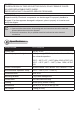
Depending on the car speed at your surveillance scene, please select an appropriate scene mode: Maximum car speed 180km/hr (110mph) 250km/hr (155mph) Scene mode LPC-Highway LPC-Freeway The Scene mode option can be found in Application > Media > Image settings. 3 English Please note the following for different applications: If you use IP9172-LPC for highway, you must select the LPR scene mode.
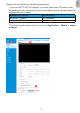
II Mounting Configuration & Dimensions Swivel Positions and Directions 135.5 mm 502.8 mm 400 mm 255 mm 105 mm 77.4 mm USABLE AREA USABLE AREA 170 502.8 360 158.
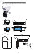
English III Component Description Ventilation fan Window frame heater coil Camera Mounting Platform Power distribution M16 1/2" Waterproof cable gland board IV Installation Suggestions If you plan to install this camera enclosure into a tropical, sea coastal, or an environment where salt water or corrosive industrial waste water/moist are present, please seal each stainless steel screws and fittings with a silicon grease compounds.
V Installation 1. Install the wall-mount bracket to a preferred location at your installation site. Drill mounting holes and a cable routing hole (if preferred) on a wall. Install the bracket. Prepare and route the wiring, Ethernet and 24V power source. 2. Flip the housing over and place it on a clean, stable surface. Secure the IR illuminator to the bottom of the housing using the included wrench and 2 hex screws.
English 3. Secure the U bracket to the IR illuminator using the included hex screws.
4. Prepare power wires, a ground wire, and a CAT5e Ethernet cable. Pass them through the M16 waterproof connectors under the housing. Ethernet cable Ø4 ~ 6.5mm Power wires & DI/DO wires, a combo cable from IR illuminator (if applied) You may need to remove the RJ45 connector, and use a crimping tool to connect the Ethernet wires to an RJ45 connector inside the enclosure. Use an Ethernet cable of the width of 4 ~ 6.5mm.
you can turn the assembly over and work on the inside of the housing. Put a foam pad below before you work on the wiring to avoid scratching the surface. 7. Assemble the camera components, e.g., the CS ring and lens module. Secure the mounting plate to the bottom of the camera (the label side) using the included screw. There is a plastic mount pad in the package. You do not need the mounting pad using the VIVOTEK camera. 9 English 6.
8. Adjust the camera's position so that the lens module can flush align with the tempered glass. Secure the camera using the screws and washers to the bottom of the housing. Lens flush w/ edge of enclosure 9. Connect 24V power source to the power input terminal. Connect power wires from the DC 12V output to the camera. Connect the 24V power output to drive the external IRs.
English IMPORTANT: You should prepare a power adaptor of the sufficient capacity for supplying 24V input. Below are the requirements: Working temperature Total consumption Power adaptor -20°C ~ 60°C (-4°F ~ -140°F): 60W -40°C ~ 60°C (-40°F ~ 140°F): 100W 3A 5A 10. Connect the Ethernet cable to the camera's RJ45 socket. 11. Also pass the combo cable of the IR illuminator through a waterproof connector. 12.
A sample connection diagram consisting of CaMate's IR illuminators and the camera is shown below. Please refer to your camera's documentation if your camera comes with different pinouts. DO+(5V) Tout DO2- DI1+ DI2+ DIRS485- RS485+ AC/DC+ PW AC/DC- PW Camera terminal block AWG26 (I) LED+: Green (I) LED-: Yellow (O) D/N+: Purple (O) D/N-: Blue (O) COM+: Orange (O) COM-: Brown AWG20 +AC24V DC12V AWG20 AC24V 13.
15. Install the housing to the wall-mount bracket by aiming and pressing the spring mortise, and hook the bracket onto the groove in the spring mortise. 13 English 14. Secure the intersection bracket to the bottom of the housing by driving two screws.
When mounting the housing, please carefully place the cable within the cutout on the bracket. There is a cutout for routing the cable. 16. Secure the housing to the bracket by fasteninng 4 T30 screws.
image. When zoom and focus is done, Close the top cover and fasten the hex screws from below. 18. Firmware configurable options: Make sure that the external IR is turned on in the night mode, and that the IR cut filter option is synchronized with the digital input you connected (default is Tout). When the "Turn on external IR illuminator in night mode" is selected, a digital output signal will be triggered to turn on the IR illuminators.
If using an iCS lens model, use the auto focus function for an optimal image. The configuration page automaticallly displays different options according to the lens you installed.
LPC-highway LPC-street LPC-parking lot If preferred, e.g., shooting fast moving vehicles, select the 60fps or 55fps frame rate. 17 English In the Configuration > Media > Image settings page, select an application scenario, LPC Highway or Freeway mode. The related parameters, such as shutter time, will be automatically changed for the scenario.
In the night mode, check if the input signals are correctly detected. You may simulate the night mode by blocking the IR unit's light sensor. Change the triggering parameters if necessary. Note that the IR unit does not immediately turns on or off. There is a 30-second buffer time. NOTE: When doing the initial testing in lab or office, the light sensor of the IR unit may not react quickly as in the outdoor environment. The lighting level in your office may not be brigtht enough to trigger the light sensor.
Mode Visible light IR light IR light enhanced Blue light enchanced Spectrum enhanced N/A ICR On Head light filter Off Remark N/A Off On Default Yes Off On Yes On Off When the Spectrum enhancement is enabled, image contrast is increased to enable better results for license plate recognition. 19 English Enter Configuration > Media > Image > IR control. Configure the Spectrum mode.
The parameters of IR illuminator can be controlled via the RS485 connection. You can enable the connection in the Configuration > PTZ > Mechanical window. Select the defaults for the IR illuminator: Pelco D, baud rate - 38400, Data bits - 8, Stop bit - 1, Parity - none.
With a motorized IR unit, the IR light zoom control buttons will be available on the home page of the camera web console. Click to change the IR lights angles. When IR lights zoom in, the light beams become narrower, the farther the lights can reach. When zoomed out, the wider the coverage, yet the range decreases. Mechanical IR Zoom functions Use the zoom buttons to control the coverage of your IR lighting.
Below is the table of configurable data bit (Data1 ~ Data4) values: bit 31 ~ 24 bit 23 ~ 21 bit 20 ~ 16 bit 15 ~ 13 bit 12 bit 11 ~ 10 bit 9 bit 8 bit 7 ~ 6 bit 5 ~ 4 bit 3 ~ 1 bit 0 Device ID: 01 (default) ~ 127 Baud rate (0)1200, (1)2400, (2)4800, (3)9600, (4)19200, (5)38400 (default), (6)57600, (7)115200 bps Brightness: (0) ~ (31), brightness from 0 ~ 100% (default), increment unit is 2.
FF012101b40009E0 FF012101b00009DC The customized buttons will appear on the main page for easy access to IR control.
This page is intentionally left blank.