
Manual

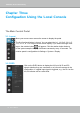

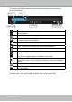


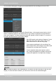

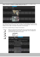
Table Of Contents
- Revision History
- Chapter One Hardware Installation and Initial Configuration
- Section One
- Management over a
- Local Console
- Chapter Two
- Introduction to the Local Console Interface
- Chapter Three
- Configuation Using the Local Console
- The Main Control Portal
- 3-3-1. Basic Search
- 3-3-2. Advanced Search
- 3-3-3. Storyboard
- 3-4-1. Settings - Overview
- 3-4-2. Settings - Camera - Management
- 3-4-3. Settings - Camera - Recording
- 3-4-4. Settings - Camera - Media
- 3-4-5. Settings - Camera - Image
- 3-4-6. Settings - Camera - Motion Detection
- 3-4-7. Settings - Camera - PTZ settings
- 3-4-8. Settings - Alarm - Alarm
- 3-4-9. Settings - Alarm - Email
- 3-4-10. Settings - System - Information
- 3-4-11. Settings - System - Maintenance
- 3-4-12. Settings - System - Display
- 3-4-13. Settings - System - UPS
- 3-4-14. Settings - System - Log
- 3-4-15. Settings - User
- 3-4-16. Settings - Storage
- 3-4-17. Settings - Network
- Settings - Network - IP
- Settings - DDNS
- Settings - Service
- Section Two
- Management over a Web Console
- Chapter Four Login and Getting Started
- 4-1. Login
- 4-2. Graphical Layout and Screen Elements - Liveview
- 4-2-4. Logo & Menu
- 4-2-5. View Cell panel
- 4-2-6. PTZ panel
- Adding Cameras to View Cells
- 4-2-7. Alarm panel
- 4-3. Graphical Layout and Screen Elements - Search recording clips
- 4-3-6. Calendar Panel
- 4-3-5. Alarm Panel
- Search Recording Clips Control Panel
- Chapter Five System Settings
- Chapter Six Operation
- Technical Specifications
- Safety and Compatibility
VIVOTEK - Built with Reliability
42 - User's Manual
Chapter Three
Configuation Using the Local Console
The Main Control Portal
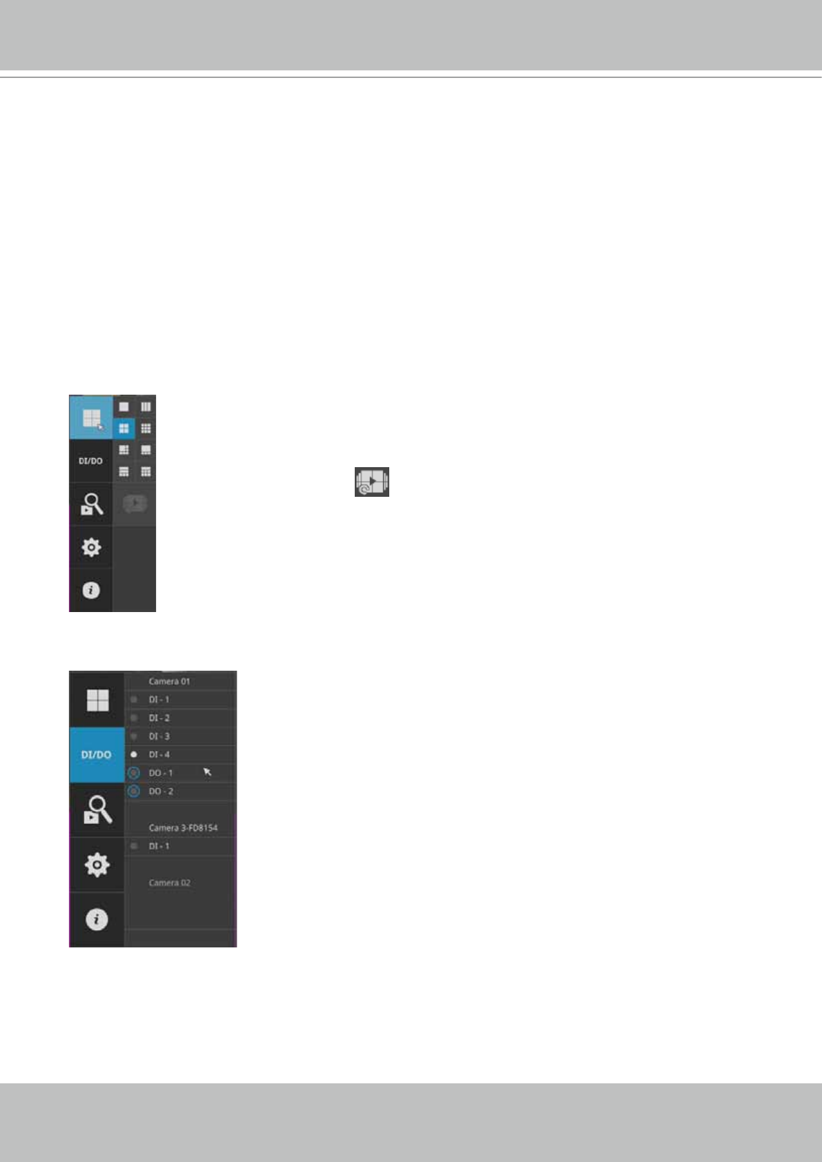
3-1. Layout
The rst functional button is Layout. You can select the 1x1, 1x3, 2x2, 3x3, 1+5,
1+3, 1+1+3, or 1+3+3 layout as the screen display. If you select the single view
layout, the rotation button
will appear. Click the rotation button below to
let the system swap the display of different cameras by every 10 seconds. The
rotation speed is congurable via Settings > System > Display.
Move your mouse cursor across the screen to display the portal.
3-2. DI/DO
Click on the DI/DO button to display the full list of all DI and DO
signals (whether they are connected or not) from all cameras in the
conguration. If a digital input signal is triggered, e.g., the DI-4 on the
left, its indicator will turn solid white.