VIVOTEK - Built with Reliability ND8322P ND8422P Network Video Recorder User’s Manual 8-CH & 16-CH (8 w/ PoE) • 2 HDDs • Auto Setup • Auto Adaptive Stream • Hardware Decoding Rev. 1.6.1.11 Rev. 1.0 Rev. 1.
VIVOTEK - Built with Reliability Table of Contents Chapter One Hardware Installation and Initial Configuration �������������������������������������������������������������������������������������� 6 Introducing the Network Video Recorder ��������������������������������������������������������������������������������������������������������������� 6 Special Features ���������������������������������������������������������������������������������������������������������������������������������������������
VIVOTEK - Built with Reliability 3-4-14. Settings - System - Log ������������������������������������������������������������������������������������������������������������ 85 3-4-15. Settings - System - EZConnect service ������������������������������������������������������������������������������������ 87 3-4-16. Settings - User �������������������������������������������������������������������������������������������������������������������������� 88 3-4-17.
VIVOTEK - Built with Reliability 5-3-2. Camera - Video ��������������������������������������������������������������������������������������������������������������������������������� 148 5-3-3. Camera - Audio ��������������������������������������������������������������������������������������������������������������������������������� 149 5-3-3. Camera - Motion detection ��������������������������������������������������������������������������������������������������������������� 150 5-3-4.
VIVOTEK - Built with Reliability Read Before Use The use of surveillance devices may be prohibited by law in your country. The Network Camera is not only a high-performance web-ready camera but can also be part of a flexible surveillance system. It is the user’s responsibility to ensure that the operation of such devices is legal before installing this unit for its intended use. It is important to first verify that all contents received are complete according to the Package Contents listed below.
VIVOTEK - Built with Reliability Chapter One Hardware Installation and Initial Configuration Introducing the Network Video Recorder VIVOTEK ND8322P and ND8422P series is a compact Linux embedded 8-CH or 16-CH standalone desktop NVR designed for any small-scale video surveillance installation. The series features ease of installation, and facilitates “One Button Setup” with its plug & play and auto setup functionality.
VIVOTEK - Built with Reliability Safety Connect the system to an earthed main power outlet. Never open the housing of the power supply unit. Install and operate the system only in a dry, weather-proof location.
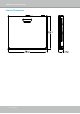
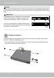
VIVOTEK - Built with Reliability Chassis Dimensions 8 - User's Manual
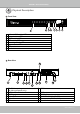
VIVOTEK - Built with Reliability 1 Physical Description Front View 2 1 1 2 3 4 5 6 7 8 3 4 5 6 7 8 LAN and PoE activity LED Network status LED eSATA activity LED HDD activity LED Recording activity LED System status LED USB ports Power button Rear View 9 1 2 3 4 5 6 1 RS-232 for opening a terminal console (for debug purposes only) 2 DI/DO terminal block 3 eSATA port 4 Audio OUT 5 Audio IN 6 VGA 10 7 8 12 11 7 HDMI 8 9 10 11 12 USB port GbE uplink port 10/100Mbit 802.
VIVOTEK - Built with Reliability NOTE: You can also use the Reset button to restore system defaults. Use a straightened paper clip to press and hold down the button for longer than 5 seconds. The system should start restoring defaults. IMPORTANT: It is important to leave a clearance of 10cm around the chassis. The clearance is required to ensure an adequate airflow through the chassis to ventilate heat. To ensure normal operation, maintain ambient airflow.
VIVOTEK - Built with Reliability 2. Secure the HDD brackets to the hard drives. 2 Label side 3. Connect SATA data cables to the connectors on the main board.
VIVOTEK - Built with Reliability 4. Connect SATA data and power cables to the hard drives.
VIVOTEK - Built with Reliability 5. Secure the hard disks to the mounting positions in the chassis with its label side facing up, and the connectors facing the inside of the chassis. 5 Note that the connectors correspond to the LED display on the front panel. The LEDs do not indicate the physical positions. 6. When done, install the top cover.
VIVOTEK - Built with Reliability 3 Interface Connections 1. Connect to a monitor using an HDMI cable. VGA is also supported. 2. Connect CAT5e or better-quality Ethernet cable to IP cameras. The Ethernet ports provide PoE power. The maximum power per port is 15.4 watts. However, please note that the total budget is 40 watts by every 4 PoE ports. 3. Connect USB devices such as, mouse, keyboard, USB optical drive, or USB thumb drive (formatted in FAT format), or UPS. 4.
VIVOTEK - Built with Reliability 16-Channel Connections (ND8422P) The ND8422P supports the connections to 16 cameras. However, the NVR comes with 8 PoE ports. The other 8 cameras should be powered by other devices, e.g., a PoE switch. The other 8 cameras should then be detected via the NVR’s Gb/s Ethernet uplink to the local network.
VIVOTEK - Built with Reliability Terminal Block Connections The terminal block pinouts is shown as follows: RS485 Alarm OUT 4 3 2 1 - + DO+DO- DO+DO- DO+DO- DO+DO- Alarm IN G8 7 6 5 G4 3 2 1 The pins are listed and described from left to right as shown in the drawing above. Pin Description NOTE RS485RS485 DataA 120Ω terminator is enabled on the bus. The terminator cannot be disabled. RS485+ RS485 Data+ Alarm OUT DO+ DC 12V±5% output, max. 40V, 50mA. Open collector design.
VIVOTEK - Built with Reliability IMPORTANT: 1. The PoE ports come with a limitation on power budget. Every 4 ports share a 40 watts power budget. For network cameras that consume large or additional amount of power, e.g., speed dome or those with embedded IR lights or heater, it is recommended you power these cameras with DC or AC power. You can still connect the Ethernet cables from these cameras to the NVR for data transmission.
VIVOTEK - Built with Reliability 4 Initial Configuration - via a Local Console A local console requires the following: 1. A monitor is connected via an HDMI or VGA cable. 2. A mouse and/or a keyboard are connected to the system. 3. It is presumed that the system has not been configured yet. Follow the onscreen messages to complete the initial configuration: 1. Select the UI language, Time zone, and current date and time. Click on the Continue button to proceed.
VIVOTEK - Built with Reliability 2. The system will then start to scan the local subnet for connected cameras. 3. All cameras detected on the network will be automatically selected. If necessary, deselect the cameras you want to exclude from the configuration. Click Continue to proceed. NOTE: 1. The maximum recording bandwidth is 64Mbps - ND8322P or 96Mbps - ND8422P. When cameras are recruited into the configuration, their stream 1 is used as the recording stream.
VIVOTEK - Built with Reliability 4. The system will automatically create volumes from the installed disk drives. The process will take several minutes. 5. An optional utility, EZConnect, is available through the Apple and Android App Stores. The EZConnect works with a server hosted by VIVOTEK for bridging and tunneling video requests between client devices and network cameras/CMS/NVR. The utility simplifies and facilitates network configuration for access across the Internet.
VIVOTEK - Built with Reliability 5-2. The QR code will be generated. 5-3. Open the utility from your cell phone. If you already registered an account, tap LOG IN. If not, tap SIGN UP to register an account from a VIVOTEK server. User 5-4. You can be defaulted to the Live view page. Tap the Add button below to add devices.
VIVOTEK - Built with Reliability 5-5. Tap the ADD DEVICES MANUALLY button. 5-6. You can then point your cell phone lens at the NVR screen (Step 5-3.) and use the SCAN QR CODES function to establish the connection. You may also manually enter the device ID.
VIVOTEK - Built with Reliability 5-7. The process will take several seconds to complete. 5-8. The NVR and the cameras under it will be ready for access. 6. Click the Done button. The LiveClient screen will display, and, by default, the recording from the selected cameras will immediately take place.
VIVOTEK - Built with Reliability 5 Initial Configuration - via a Web Console (Optional) IMPORTANT: If you already configured the system using an Ethernet web console, please skip the Auto Setup steps when you connect the HDMI cable. You may accidentally format your storage volumes. 1. Press the power switch on the front panel to start the NVR. Wait for the system status LED to light green. 2. From a management computer, install the IW2 utility software included in the product CD.
VIVOTEK - Built with Reliability 3. Start the IW2 utility. The IW2 utility will discover the NVR located in the same subnet. 4. Double-click on the ND8422P or 8322P entry to start a web session with the NVR system. 5. The login page will prompt. Enter "admin" and "admin" as user name and password for access for the first time. Expand the menu on the right of the Login button. Select and click on the Settings button to begin your configuration.
VIVOTEK - Built with Reliability 6. On the Settings page, click on Storage > Volume to access your storage volume configuration. 7. On the Storage settings page, check if your hard drives are present and identified by your system. Click on the Create... button. 8. Refer to the later discussions for the rest of the configuration procedure.
VIVOTEK - Built with Reliability 6 LED Indicators 1 Name Behavior 1. PoE & 1 Network LED 2 3 2. NET activity 1 LED 2 3 3. eSATA LED 1 2 4. HDD activity 1 LED 2 3 5. Record LED 6. Status LED 4 1 2 1 2 3 7. Power button 1 LED 2 2 3 4 5 6 7 Definitions Flashing Green OFF Solid Green Flashing Orange Solid Orange OFF Solid Green OFF Constant Green Constant Red Transmitting or receiving data. Device disconnected. Device is connected. Indicating on-going traffic over the LAN connection.
VIVOTEK - Built with Reliability 7 Power Up and Power Down To power up and power down, On the initial configuration: 1. Connect the power adapter between the system and power outlet. 2. Turn on the system by pressing the power button for more than one second. After the initial connection, 1. Press the power button for 1 second to power on. 2. Press the power button for 4 seconds to power down. the system should start flushing the cached contents in system memory and gracefully shut down. WARNING: 1.
VIVOTEK - Built with Reliability Section One Management over a Local Console Chapter Two Introduction to the Local Console Interface Camera 01 Camera 02 Camera 03 Camera 04 Camera 05 Camera 06 Camera 07 Camera 08 Camera 09 User's Manual - 29
VIVOTEK - Built with Reliability By default, a live view appears on an HDMI monitor. The interface architecture of the local console is illustrated as follows: LiveView Main screen Main control portals Layout DI/DO PTZ PiP Play recording clip Audio DI/DO Snapshot | Manual recording Search panel Search recording clip Settings Storyboard Overview (camera connection & storage) Stop buzzer Camera Config. portal Alarm Deselect camera Camera portal When a view cell is selected.
VIVOTEK - Built with Reliability 2-1. How to Begin 1. How to access the Configuration Portal? Make sure a mouse is attached to your NVR. Move your mouse cursor, and the Configuration Portal will appear on screen. For all the configurable options available through this portal, please refer to Chapter 3 on page 43. You can also hide these portal toolbar. Right-click on the LiveView screen to display the option. 2.
VIVOTEK - Built with Reliability PTZ control panel for ordinary PTZ type PTZ control panel for joystick type PTZ 3. How to retrieve and access recorded videos? 3-1. One is to access the video clips taken within 2 hours. Left-click to select a view cell, and then click on the Recording clips button. Select a time value by a single click. You will be prompted for User name and Password, enter admin and admin (the default user name and password), and then click Login.
VIVOTEK - Built with Reliability The Playback window will prompt, and a playback begins from the point in time you selected, e.g., 30 seconds ago. This function allows you to quickly review what has just happened. 3-2. Another way to access past videos is to open the Search recording clips window. Move your mouse cursor to display the Configuration Portal (without selecting any view cell). Click on the Search recording clips button. Please refer to page 44 for more information about the search functions.
VIVOTEK - Built with Reliability 4. How to recieve system alarm? Please refer to page 71 for how to configure system alarm triggers. When the alarm is triggered, e.g., by digital inputs or motion detection, an alarm message will prompt on the screen. Use the > arrow button to browse through the alarm messages. If the alarm is configured with video recording as the responding action, you can click on the alarm entry.
VIVOTEK - Built with Reliability 5. Why live view is unavailable? The default live view receives a camera's stream #1. If a camera's stream #1 is configured using MPEG-4 as the video codec, the following message will prompt. You can go to the Settings > Camera > Media > Video window to configure the video codec of stream #1 into H.264.
VIVOTEK - Built with Reliability 6. How do I move to another layout page? Move your cursor to the right hand side of your screen. The page turner buttons will appear as shown below. For example, if you have 8 cameras placed on 2 2x2 layout pages, use these buttons to visit different pages. 7. Why the onscreen tool bars disappear after some time? The system comes with idle modes. Below are the applicable conditions: 1.
VIVOTEK - Built with Reliability 2-2. Operation on Camera View Cell 2-2-1. PTZ Panel Once you selected a camera, click on the PTZ button on a camera portal. The PTZ panel will prompt. Below are the description of its functions: List of preset positions Focus far Focus near Home Zoom in Zoom out Starts patrol 1. PTZ control: Click and drag the nudget in the center towards the direction you wish to move to. 2. Focus: Click on the Focus near and Focus far buttons to adjust camera focus. 3.
VIVOTEK - Built with Reliability Below is the PTZ panel that appears with ordinary PTZ cameras. List of preset positions Speed selector Focus far Focus near Zoom in Zoom out Starts patrol 1. PTZ control: Click on the arrow buttons to move towards the direction you wish to move to. 2. Focus: Click on the Focus near and Focus far buttons to adjust camera focus. 3. Zoom: Use the Zoom in and Zoom out buttons to adjust the camera's zoom ratio. 4.
VIVOTEK - Built with Reliability 2-2-2. PiP (Picture in Picture) Panel PiP is short for Picture in Picture, a function that provides digital zoom into a live video. When activated, a Global view window will appear at the lower right of the view cell as shown below. You can display only a portion of the complete video frame as an area of your interest. Using a click and drag on the ROI window, you can instantly move to other areas within the video frame.
VIVOTEK - Built with Reliability 2-2-3. Play Recording Clips Panel The Play Recording Clips function provides a shortcut to the latest recordings on the system. You can select 30 secs, 1 min, 3 mins, 10 mins, and 60 mins for an immediate playback. For security reasons, using this function requires users to enter his/her credentials. The Playback window will prompt, and a playback begins from the point in time you selected, e.g., 30 seconds ago.
VIVOTEK - Built with Reliability 2-2-4. DI/DO The DI/DO panel provides a glimpse of all DI and DO signal statuses from the connected cameras. You can manually trigger a digital output by clicking on its indicators. When a digital input is triggered, its status will also be indicated on the panel. WARNING: Please note that DO is triggered by one click. You should then click again to disable the DO. Otherwise, the DO signal will be continuously triggered.
VIVOTEK - Built with Reliability 2-2-6. Right-click Commands Left-click to select a camera. Right-click to display the selection menu. 1. Camera information: Click to display camera name, resolution, codec, or frame rate on the view cell. The information will display on the upper left corner of a view cell. 2. Fit screen with ratio: The NVR server automatically optimizes the display camera view cells.
VIVOTEK - Built with Reliability Chapter Three Configuation Using the Local Console The Main Control Portal 3-1. Layout Move your mouse cursor across the screen to display the portal. The first functional button is Layout. You can select the 1x1, 1x3, 2x2, 3x3, 4x4, 1+5, 1+12, 1+3, 1+1+3, 1+3+3 layout as the screen display. If you select will appear. Click the rotation the single view layout, the rotation button button below to let the system swap the display of different cameras by every 10 seconds.
VIVOTEK - Built with Reliability 3-3. Search recording clips 3-3-1. Basic Search Click the button to start searching for recorded clips. A confirm box will prompt. Enter User name and Password to proceed. The search and calendar view will appear. Select a day on the calendar when the the recordings took place (the days with recorded clips will be highlighted in blue and green). Double-click on a day to begin playback and search.
VIVOTEK - Built with Reliability The timeline bar enables quick skimming through the recording. Its functions are described as follows: Span of existing recording Current time indicator Control buttons Timeline scale Buttons Functional buttons Description Time scale selector. Use the buttons to select the span of time displayed on the tool bar. Previous frame. (I-frame only) Next frame. (I-frame only) After you paused a playback, use this button to browse video frame by frame. Play backwards. Play.
VIVOTEK - Built with Reliability The fisheye dewarp modes can be selected during a playback: e.g., 1R, 1P, and 1O3R. When playing the video recorded by a fisheye camera, the fisheye display options will be available on screen. You can click to select the 1O, 1P (Panoramic), 1R (Regional), or 1O3R (1 Original and 3 Regional) modes. If 1P, 1R, or 1O3R mode is selected, you can exert the mouse control on screen, such as swiping the view, or hold down the mouse button and swipe the field of view.
VIVOTEK - Built with Reliability Note that to export a video segment from the playback timeline, 1. Click on the Export button , 2. Insert a USB drive formatted in the FAT format. 3. Select the "From time" by clicking on the timeline. You can also manually enter the "From time" and the "To time." 4. Click on the "From time" tab using a single click. 5. Repeat steps 3 and 4 to configure the To time. 6. Click on the Export button. 2 1 The export process is indicated on the right.
VIVOTEK - Built with Reliability 3-3-2. Advanced Search Click on the Advanced search button on the upper left of the screen to enter the Advanced Search mode. You can specify the search criteria by selecting the devices to be involved in the advanced search.
VIVOTEK - Built with Reliability You can then specify the start time and end time to configure a span of time to be searched. You can also determine what alarms will be included in the search.
VIVOTEK - Built with Reliability You can select what types of triggers were associated with the recordings you want to find. When done with the selection, click on the Search button. In the sample screen below, a list of alarms is displayed, and you can double-click on any of them to replay the moment when the alarm was triggered. The alarm-related recording will typically include a length of 5 seconds of pre-alarm and 20 seconds of post-alarm footage. Up to 200 search result entries will appear.
VIVOTEK - Built with Reliability 3-3-3. Storyboard The Storyboard interface provides a glimpse of past recordings over a timeline. It looks like doing the film editing after a film was shot. To enter the Storyboard window, click on the Storyboard shortcut on the upper-left of screen.
VIVOTEK - Built with Reliability Mouse over the line of snapshots to display its time of recording. Click on a snapshot of your interest. The time of recording is immediately displayed on top of it. The detailed search is based on a narrow-down criteria. The search begins from a 24-hour time span, and then moving in to a 4-hour, 1-hour, 10-minutes, and 2-minutes span. When the screen displays a 24-hour span, each snapshot represents a 3-hour time span.
VIVOTEK - Built with Reliability If you find yourself in the wrong segment on the timeline, use the buttons on the upper-right of the screen to travel. The definitions of these buttons depend on the time span of your current position. For example, if you are in a 4-hour time span, the "Back to previous state button" will bring you back to the 24-hour time span. Previous Next Back to previous state # hours/mins # hours/mins The smallest time span is 2 minutes.
VIVOTEK - Built with Reliability The playback window will appear. Please refer to page 45 for the operation details. 17:15:41 2014.03.14 1x To return to the Live View window, click on the Back to Search recording clips button the Back to Liveview button 54 - User's Manual on the upper-left of the screen.
VIVOTEK - Built with Reliability 3-4. Settings 3-4-1. Settings - Overview Click the Settings button to start the camera and system settings window. A confirm box will prompt. Enter User name and Password to proceed. The system will default to the overview page displaying the camera connection and storage statuses. An empty position will be left in blank, and a disconnected camera will be indicated as spaces. .
VIVOTEK - Built with Reliability The Camera menu provides access to Management, Recording, Media, Image, Motion detection, and PTZ settings pages. 3-4-2. Settings - Camera - Management On the camera Management page, you can configure the following: 1. Recruit or disband cameras. 2. Create a camera name. 3. Assign User name and Password, or apply the credentials to all cameras in your configuration. 4. Change the Network settings. 5. Change the cameras' positions on the layout screen.
VIVOTEK - Built with Reliability To recruit cameras: 1. Click on the Add button. A list of cameras in the same subnet will appear. 2. Click the Add button, the camera will be placed at an unoccupied position. You may also expand the menu on the side of the Add button to select a position number. 3. When a camera is added, it should appear on the graphical placement below. 4. Click the Apply button after you added cameras. 5. You may click the page back button to return to the previous window.
VIVOTEK - Built with Reliability To disband cameras: 1. Click on the Remove button. A list of cameras will appear. 2. The Remove button will turn yellow . Mouse over to the camera you want to remove, and its entry will display the Remove message. 3. Click on the Remove message. The camera should then disappear from the camera list. The recording from that camera will also be discontinued.
VIVOTEK - Built with Reliability Network On the Network tabbed window, you can configure the network type, IP address, and the connection ports for video streaming. You can select DHCP as the method for cameras to acquire IP addresses, or you can manually configure static IPs for a single or all cameras. Using static IPs is recommended. Although the NVR can remember the MAC addresses of cameras, if IPs are changed under the DHCP configuration, your NVR may still fail to connect the cameras.
VIVOTEK - Built with Reliability Camera position To change a camera's position on the Liveview layout, click and drag a camera to an unpopulated position. Note that you cannot swap the positions of two cameras by dragging a camera onto a position already populated by the other. Also, the camera index number on the management list is not affected by the change of positions. Click the Apply button for the configuration change to take effect.
VIVOTEK - Built with Reliability 3-4-3. Settings - Camera - Recording Recording options On the camera Recording page, you can configure the following: 1. Configure the duration of camera events, for the concern that camera can be too frequently triggered. 2. Enter the Pre- and Post-event recording time. The triggering events can be DI, DO, Motion detection, PIR, or Tampering detection. 3. The default recording stream is Stream 1, and the system automatically adjusts the frame rate, resolution, etc.
VIVOTEK - Built with Reliability Recording Schedule By default, all video feeds from cameras are recorded at all time. You can modify the recording task using the schedule tool: 1. Click to select a recording condition's checkbox - 1. Continuous recording recording , and 3. Clear , Event (no recording). 2. Click and drag on the cells on the time table. For example, to stop the recording during a period of time, select the the Clear checkbox and move the cursor across the time table.
VIVOTEK - Built with Reliability 3-4-4. Settings - Camera - Media Stream management The stream here refers to the recording stream, namely, Stream 1. You can use these preset conditions to configure the resolution, image quality, frame rate, and the bandwidth consumption of the recording stream on this window.
VIVOTEK - Built with Reliability Video The Video window allows you to configure all video streams (the no. of stream available can be different for different models). You can configure the following: 1. Codec: video compression codec in H.264, MPEG-4, or MJPEG. Note that MPEG-4 is not supported for Liveview. 2. Frame size: video resolution. Note that due to the limited CPU resources, you may not be able to change the resolution to a very high value, e.g., 5MP in the 1920x1920 resolution. 3.
VIVOTEK - Built with Reliability Audio The Audio window allows you to configure all audio codec, sampling rate, and Microphone input gains. Depending on design of the camera models, some codecs may not be available. Also, there are cameras that come without embedded mircrophones.
VIVOTEK - Built with Reliability 3-4-5. Settings - Camera - Image Display The Display window allows users to tune the image display options: 1. Video name: the video name is displayed on the title bar that is displayed on each view cell. The screen shot below shows a name as "Speed dome." 2. Video name and timestamp: Default is enabled. If enabled, the video name and time is displayed on the view cell. 3.
VIVOTEK - Built with Reliability Image adjustment The Image adjustment window allows users to tune the basics about image display options: 1. Color: Select to display image as color or black and white. 2. Brightness. 3. Saturation. 4. Contrast. 5. Sharpness. 6. High TV line, Gamma curve, low light compensation, etc. The rest of the options depend on the lens and image sensor type of each individual camera. Therefore, the options here can vary.
VIVOTEK - Built with Reliability 3-4-6. Settings - Camera - Motion Detection Motion Detection To set up a detection window: 1. Select a camera by a single click. 2. Use the PTZ panel to move to a field of view where you want to place a detection window. 3. Click and drag to draw a rectangular detection window. 4. Pull the detection area level up to a preferred position. An object must be larger than the detection area to trigger an alarm. 5. Select a Sensitivity level using the slide bar. 6.
VIVOTEK - Built with Reliability 3-4-7. Settings - Camera - PTZ settings To configure PTZ preset positions: 1. Select a PTZ camera by a single click. 2. Use the PTZ panel to move to a field of view where you want to designate as a preset position. 3. Click the add button, and enter a name for the position. Press Enter to proceed. Repeat the configuration to create more positions. 4. Click the Apply button for the configuration to take effect. Note that the PTZ panel can vary with different PTZ cameras.
VIVOTEK - Built with Reliability To configure a patrol: 1. Click to enter the Patrol menu. Select a preset position if you want to change its position on the patrolling order. 2. Click the up and down buttons to change the position on the order, or click the remove button to disband a position from the order. You can also change the interval to stay before moving from one position to the next position. 3. You may then click on the Preview patrol button to see if it runs as expected. 4.
VIVOTEK - Built with Reliability 3-4-8. Settings - Alarm - Alarm The events reported from individual cameras' digital inputs, digital outputs, and motion detection can be accommodated in the NVR system's alarm settings. These events will then be reported or trigger corresponding actions as follows: 1. Reporting events via Email or system buzzer. 2. Triggering video snapshot and text message by the occurrences of events to an FTP site. 3. Triggering the camera(s) for its lens to move to a preset position.
VIVOTEK - Built with Reliability To create an alarm, 1. Click on the Add button . You can manually enter a name for the current setting. You can enter up to 16 numeric or alphabetic characters for the name, including symbols such as [0-9][a-z][A-Z][_][ ]. You can also designate the interval between one alarm and the next triggered alarm to avoid the situation that the alarms can be too frequently triggered. Click on the next button to proceed.
VIVOTEK - Built with Reliability 3. On the Trigger window, select system triggering conditions, or one or more cameras by selecting their checkboxes. The number of DI or DOs on each camera is automatically detected and displayed through individual checkboxes. The Motion detection function, if there are many detection windows configured on a camera, is all triggered by one checkbox. Note that the triggering sources will be listed even if the camera is currently not connected.
VIVOTEK - Built with Reliability 4. On the Action window, you can select the Action type from a drop-down menu. The configuration details of each action type is discussion below. 4-1. Recording - When an event is triggered, the selected camera will record a video footage of the length defined by the pre-/post-event setting, to the NVR system. 4-2. Email - The Email action sends an Email to the administrator along with a snapshot of the event.
VIVOTEK - Built with Reliability The Email subject and addresses can be composed of 254 characters in numeric or alphabetic characters including: [0-9][a-z][A-Z][_][ ][-][.][,][@]. You can enter the addresses of multiple recipients. Use semicolons, (;), to separate the addresses of multiple recipients. 4-3. Buzzer - The buzzer is sounded on the occurrence of the event.
VIVOTEK - Built with Reliability 4-4. FTP - Snapshots from specified cameras can be uploaded to an FTP site on the occurrence of an event. Enter the FTP site address in the dotted-decimal notation, e.g., 159.22.151.20. Enter the login name and password for the user account. You can enter a directory name you prefer on the FTP site. The server port default is 21, a different number between 1025 and 65535 can also be assigned. The snapshot thus delivered has a size of 320x240 pixels.
VIVOTEK - Built with Reliability 4-5. Camera DO - A triggered alarm triggers a camera's DO, e.g., an alarm siren. 4-6. Camera pan-tilt-zoom - A PTZ capable camera can move its lens to the preset position in case of a triggered alarm. For example, a triggered sensor may indicate an area of interest has been intruded, and a camera's field of view should be moved to cover that area. The precondition is that you properly set up preset positions on your PTZ cameras using a local or a web console.
VIVOTEK - Built with Reliability 4-7. System DO - A triggered alarm can be used to toggle the NVR's digital output, e.g., to sound an alarm siren.
VIVOTEK - Built with Reliability 5. On the Schedule page, you can select to activate or de-activate alarm triggers throughout a specific timeline. For example, in some situations you can disable the alarm triggers during the office hours, and choose to enable the triggers only during the off-office hours. 6. Click Finish to end the configuration. 7. Repeat the process above to create more alarms according to the needs in your surveillance deployment.
VIVOTEK - Built with Reliability 3-4-9. Settings - Alarm - Email This window provides an interface where you can configure the connection to a Mail server. Via the Mail server, the system can deliver Emails containing system alarm messages to multiple receivers. A reachable Mail server and Email accounts must be provided before you can apply the settings. The configuration options are identical to those found in the Email configuration in Settings Alarm window.
VIVOTEK - Built with Reliability 3-4-10. Settings - System - Information On this window, you can configure the following: 1. Change the system name. 2. Select the UI text language. 3. Configure system time, time zone, and if you are connected to a DNS server where Auto Daylight Saving time can be applied, you can acquire the associated setting from a server within your network. 4. Click the Apply button for the configuration to take effect.
VIVOTEK - Built with Reliability 3-4-11. Settings - System - Maintenance If the need arises for updating system firmware, acquire the update from VIVOTEK's technical support or download site. Locate the firmware binaries, and click the Import button. The upgrade should take several minutes to complete. Note that during the upgrade, the recording task will be interrupted. On this window, you can perform 4 maintenance tasks: 1.
VIVOTEK - Built with Reliability 3-4-12. Settings - System - Display On this page, you can configure the system to consecutively display (rotate) cameras' view cells on the Liveview window. For example, if you have 8 cameras in 2 2x2 layouts, the rotation can let you see the live views of all cameras by every few seconds. You can also enable or disable the Alarm notification. To enable the rotate function, click on the rotate button on the layout panel.
VIVOTEK - Built with Reliability 3-4-13. Settings - System - UPS On this page, you can configure the system to gracefully shut down when UPS battery is lower than a certain level. You may also let it shut down when the estimated sustainable time is reached.
VIVOTEK - Built with Reliability 3-4-14. Settings - System - Log System logs are categorized as System, Recording, User, and Error. To display system logs, select a range of time and click on the Search button. You can search for past logs in each category window.
VIVOTEK - Built with Reliability 86 - User's Manual
VIVOTEK - Built with Reliability 3-4-15. Settings - System - EZConnect service This window provides access to the EZConnect configuration. Please refer to page 20 for how to configure system access using the EZConnect functionality.
VIVOTEK - Built with Reliability 3-4-16. Settings - User The User window allows you to create more users, to change user password, and place limitations on users' privileges and administration rights. Up to 16 users can be created, including the default administrator. 1. By default, there are two user groups: Administrator and Regular user. 2.
VIVOTEK - Built with Reliability To create or edit users, 1. Select a User group by unfolding its pull-down menu. Select either an Administrator or regular user as the user group. 2. Enter the User name and password. The max. number of characters for a user name is 64, with alphabetic and numeric characters including [0-9][a-z][A-Z][_][ ][-][.][,][@]. The max. number for password is also 64.
VIVOTEK - Built with Reliability 3. If you are creating a regular user with limited access to cameras, deselect the checkboxes by the cameras to deny the user access. 4. Click Apply to close the configuration window. Repeat the process to create more users. 3-4-17. Settings - Storage The storage page displays the volume information including physcial position, total capacity, used and free space, and associated commands such as Format and Delete.
VIVOTEK - Built with Reliability Attribute: The various attributes can vary from different HDD manufacturers. Value: Value for the currently selected attribute. Worst: Worst value acquired for that attribute. Threshold: A predefined threshold or triggering value. The threshold below which the normalized value will be considered exceeding specifications. Raw value: The detected parameters for that attribute. Status: The judgement made to deem the current reading as OK or failed.
VIVOTEK - Built with Reliability 3-4-17. Settings - Network Settings - Network - IP DHCP: Default is selected, the server obtains an available dynamic IP address assigned by the DHCP server each time the system is connected to the LAN. Manual setup: Select this option to manually assign a static IP address to the Network Camera. Enter the Static IP, Subnet mask, Default router, and Primary DNS provided by your ISP. Subnet mask: This is used to determine if the destination is in the same subnet.
VIVOTEK - Built with Reliability Settings - DDNS VIVOTEK provides Safe100.net, as a free DDNS dynamic domain name service for users who want access from the internet or a domain name service for the NVR. VIVOTEK maintains a database of product MAC addresses for the Safe100.net service, and you can apply one domain name for each NVR system. DDNS Enable: Select this checkbox to enable the DDNS setting. Enter a Host name, Email address, and password twice, and then click Apply to proceed.
VIVOTEK - Built with Reliability Settings - Service By default, the NVR service and video streaming are accessed via HTTP port 80 and RTSP port 554. You can designate a different port number if the need arises. Usually it is not necessary to change these ports. HTTPS encrypted connection is enabled by default. Instead of a web console, you can also access the NVR and the subordinate cameras using the iViewer and VIVOTEK's VAST software.
VIVOTEK - Built with Reliability 3-5. Information This window shows the revision number of the firmware running on this machine.
VIVOTEK - Built with Reliability Section Two Management over a Web Console There are two different interfaces on the system: 1. One is connecting mouse and keyboard, and an HDMI cable to a TV screen or monitor. The local management thus made is described in Section One of this manual. 2. The other is accessed through the Ethernet connection. Management via a web console will be described in Section Two of this manual.
VIVOTEK - Built with Reliability Chapter Four Login and Getting Started 4-1. Login This is the login page on the browser. The minimum for resolution is 1280x960. If you enable the IE7 compatible mode when using the IE8 browser, please disable the compatibility function. While you are in the browser, press F12 to check its status. It is highly recommended that you should change the default password. Please refer to Settings > Security > User account page to see how to prevent unauthorized access.
VIVOTEK - Built with Reliability You may login to a different software utility by unfolding the side panel on the Login button. You can also select a different language using the Multilingual selector menu on the lower left corner of the Login screen. The functional items, menus, and dialogues will then be displayed using the selected language. Remember me: Select the checkbox to save your user name for use on the next login. The user name will be preserved in browser cookies for two days.
VIVOTEK - Built with Reliability Login options: You may also mouse over the Login button to display the login options. You can then enter the Liveview, Playback, or Settings window. The NVR system features a simple UI structure which consists of a Liveview window, a Playback utility, and a system Settings window. Once logged in, you can move from one window to another by selecting the hot link buttons on the upper right of the screen.
VIVOTEK - Built with Reliability IMPORTANT: 1. Before operating the NVR, make sure you have properly installed hard drives and configured the storage volumes. Otherwise, you will not be able to operate some of the system's functionality. 2. Since the NVR system comes with 32-bit plug-ins for screen control, if your PC runs a default 64-bit IE browser and you manually enter the NVR's address on the browser, your browser session may malfunction.
VIVOTEK - Built with Reliability 4-2. Graphical Layout and Screen Elements - Liveview 3 4 2 Layout Layout contents Logo & Menu 1 Camera list 7 Alarm panel 6 PTZ panel 5 Viewcell panel Once you log in, the system defaults to the Liveview page, which provides access to other configuration utilities, live view screen, and other functional panels. The screen elements are described as follows: Item 1 Name Camera List Description Provides a glimpse of all cameras inserted into your configuration.
VIVOTEK - Built with Reliability 4-2-1. Camera List Panel The camera list displays the recruited cameras by the sequential numbering order you configured in the System Settings utility. Sorting criteria Camera thumbnails Page switcher Depending on the size and screen resolution of your monitor, the snapshots of 8 cameras are displayed in this panel. If a user logged in using a credential of a limited access, he may only see cameras that he can access instead of all of the cameras.
VIVOTEK - Built with Reliability * Snapshot: the camera's image snapshot is replenished every 5 minutes. If a camera is disconnected, the last image taken will be used to represent a camera. * Camera index & Camera name: Placing the mouse cursor on top of a camera text displays the camera index number and the camera name. You can click on the camera index to display the information box. * Status: Online: the online status can be accompanied by the DI/DO icon Offline: camera is disconnected.
VIVOTEK - Built with Reliability 4-2-2. Layout 1x1 1+3 1+5 2x2 3x3 User layout #1 User layout #2 User layout #3 By default, 5 typical layouts are provided for the user. They include: 1x1, 2x2, 3x3, 4x4, 1+3, 1+5, and 1M+12. System default is the 4x4 layout. Cameras that do not fit into the first page of a layout, say, a 3x3 layout, will be displayed on the succeeding layout pages. Each functional button on the screen is activated by a mouse hover.
VIVOTEK - Built with Reliability 4-2-3. Layout contents A few functional buttons are available on the Layout contents page. Clears all view cells on the current layout. Full view: extends the view cells on the current layout to the full of the screen. Rotate: the rotate function lets system display successive layout pages by the intervals of 10 seconds. The layout page that does not contain camera views will be skipped. A Rotate action will stop when you 1. move to another page, 2.
VIVOTEK - Built with Reliability 4-2-5. View Cell panel A single view cell is shown below. Each view cell contains a video stream display area, an information bar, and functional buttons at the bottom. A view cell is displayed in Normal, Focused, or Maximized mode. 1. A single click selects a view cell from the View Cell panel, enables its function buttons, and turn it into the Focused mode. 2. The 2nd click maximizes the size of the view cell to the full of the panel. 3.
VIVOTEK - Built with Reliability A view cell attempting to connect to a network camera will look like this. If the connection attempt takes a long time, it may result from network problems or incorrect configuration with video streaming. For example, you may have configured the camera to be streaming a 5MP stream. The NVR uses video stream #1 for recording, and stream #2 from cameras for live viewing.
VIVOTEK - Built with Reliability Information Bar Status icon Camera index Video time Status icon Description Connected with live streaming; a single click on this icon can trigger a manual recording. Connected and recording video to system storage. Disconnected or trying to establish a connection. NOTE: If you disable the Manual recording function on the Settings page, you will not be able to use the Manual Recording function on the Liveview.
VIVOTEK - Built with Reliability The time display format is as follows: yyyy/m/d/yyyy hh:mm:ss 2014.05.05 16:15:41 Tool Bar Buttons Buttons Description Resumes streaming. Pauses a video stream. Adds a Bookmark (that saves a short description and a one-minute footage from the current feed) Takes a snapshot. Removes camera from the view cell. Mutes (if there is audio input from the camera.) Unmutes Stream selector. Restores the view cell's original position on the Liveview panel.
VIVOTEK - Built with Reliability Tool Bar Functions in Details 1. Play and Pause buttons: These buttons pause and resume a video stream currently being played on your web browser. Note that this operation does not affect the video recording taking place between a camera and the NVR system. 2. Bookmark: This function allows you to place a bookmark on a recorded stream when you observe a situation from your live view window.
VIVOTEK - Built with Reliability Below are two bookmarks (yellow tags) shown along with a recorded video in the Playback utility screen. Bookmarks help find and retrieve important moments in a recoded video. NOTE: Bookmarks will be erased if the user/system erases the video clips they were appended to. For example, system will recycle storage space by deleting old videos along with their bookmarks. 3. Snapshot: This button produces a snapshot prompt.
VIVOTEK - Built with Reliability 4. Clear: This button removes camera from the current view cell. The view cell will then be available for other cameras 5. Mute and Unmute: These buttons stops or resumes audio from a live stream. 6. Restore: This button restores the view cell's original position on the Liveview panel. 7. Maximize: This button extends the size of current view cell to the full of the Liveview panel. 8.
VIVOTEK - Built with Reliability 9. Volume controller: The volume control takes effect when audio input from the network camera is available. Audio is heard only from a focused window, one that you selected by a mouse click from the Liveview panel. Some network cameras do not come with an embedded microphone, and its audio is disabled by system default. The actual sound level is also dependent on the system volume of the PC having a web console with the NVR.
VIVOTEK - Built with Reliability 1R (Regional view) 1R View (Single Regional View) Zoom In Zoom Out Zoom in/out & all-directional navigation control The 1R mode (or rectilinear) provides access to one image section within the hemisphere. You can zoom in or out (using the mouse wheel or PTZ panel) or travel through to other areas within the hemisphere using simple mouse clicks and drags. A single click on a particular object can bring the object to the center of your view window.
VIVOTEK - Built with Reliability 4-2-6. PTZ panel The PTZ panel takes effect for cameras that come with mechanical PTZ functions. It does not support digital PTZ functions. To utilize its functions, select a view cell populated by a PTZ camera, such as a speed dome. Depending on the individual functions that come with PTZ cameras, some functions will not be available for every cameras.
VIVOTEK - Built with Reliability PTZ presets: If your PTZ cameras have preset locations, click on the button to unfold the preset menu. Click on any of the preset locations to move to the area of your interest. Refer to your camera's User Manual for how to configure preset locations. The following message will prompt if the camera has no preset locations. Pan/Tilt controller: A mouse hover over the arrow buttons activates the arrow button. Use the buttons to navigate to a preferred location.
VIVOTEK - Built with Reliability Auto pan/patrol controller: These buttons provides pan and patrol functions provided that preset locations have been configured on the camera. For a speed dome camera, the pan command tells the camera to continuously pan 360 degrees until it is stopped by a user command. For PZ or PT series cameras, the pan action only takes place once to cover reachable areas. The Stop button ends a pan or patrol tour. 4-2-7.
VIVOTEK - Built with Reliability If an event is configured with a recording action, there will be a play button to the left of the alarm message. The alarm playback window will begin playback of a footage taken 10 seconds before the occurrence of an alarm. The playback of an alarm-triggered recording will normally last for one minute. If, however, you configured a shorter pre- and post-alarm recording time, your alarm recording may be slightly shorter.
VIVOTEK - Built with Reliability Move your cursor over an alarm with a recorded footage. The Play button will become available. The following buttons are available in the alarm playback window. Buttons Description View live video: displays the live view streaming instead of the alarm recording. Resumes the alarm playback. Begins the alarm playback. Pauses the current playback. Mute or unmute the audio with the current playback. Drag the controller to change the audio volume level.
VIVOTEK - Built with Reliability Incoming Alarms New alarms will be indicated by the messages in bold letters, the alarm bell icons, and the increasing number of unread messages on the title bar.
VIVOTEK - Built with Reliability 4-3. Graphical Layout and Screen Elements - Search recording clips 2 3 Layout contents Logo & Menu 1 Camera list 6 Calendar 5 Alarm panel 4 Playback panel The screen elements of the Playback window are described as follows: Item 1 2 3 Name Camera List Description Provides a glimpse of all cameras that have recorded data. Basic information is also provided along with a screenshot.
VIVOTEK - Built with Reliability 4-3-1. Camera List Panel The camera list displays the 8 recruited cameras by the sequential numbering order you configured in the System Settings window on page 142. The elements in the Camera list on a Search recording clips window are identical to those on a Liveview window. Please refer to page 102 for details on the Camera list panel. There are two key differences between the Camera List on Liveview and that on the Playback window: 1.
VIVOTEK - Built with Reliability 4-3-2. Search Recording Clips Layout 3 types of layouts are provided for the Search recording clips window: 1x1, 2x2, and 1+3. In the Search recording clips window, users can simultaneously playback up to 4 recorded videos. Clears all view cells on the current layout Starts or stops the Synchronous playback. Full view: extends the view cells on the current layout to the full of the screen.
VIVOTEK - Built with Reliability 4-3-4. View Cells in Search Recording Clips The view cells in Liveview and Playback windows are similar. Their differences are listed as follows: 1. 3 simple layout types are supported as previously described. 2. The information bar displays camera index and video time information only. 3. The Play and Pause buttons are not available on the Tool bar. One Export function is added on a playback view cell.
VIVOTEK - Built with Reliability Search Recording Clips Control Panel Timeline slider Span of existing recording Control buttons Playback info Timeline zoomer The time slide bar enables quick skimming through the recording. Its functional buttons are described as follows: Buttons Description Pause Play. This button is available after you manually pause a playback. Stops the current playback. Next frame. After you paused a playback, use this button to browse video frame by frame. Speeds down by 1/2.
VIVOTEK - Built with Reliability The time line shows the length of existing recording taken on a specific time span. You can use the timeline zoomer to scale down the span of time. For example, if the time span is reduced to 1 hour, then each section on the time line represents 15 minutes of recording. The total time span of a timeline starts from the minimal of 4 minutes, 20 minutes, 40 minutes, 1 hour, and up to a maximum of 24 hours.
VIVOTEK - Built with Reliability 4-3-5. Alarm Panel The alarm panel displays the alarms or bookmarks recorded by the day of recording. Two additional buttons are available: Page selector and Alarm filter. Page selector Alarm filter See page 163 for how to configure alarms. • A playback button will be available with an alarm-triggered recording. The alarm panel in the Playback window also supports the List mode and Icon mode that are similar to that in the Liveview window.
VIVOTEK - Built with Reliability 4-3-6. Calendar Panel Double-click on any of the existing cameras to display the Calendar panel. Days with recorded videos will be highlighted in blue regardless of the length of existing recordings that occurred in that day. You may then click on a day to begin viewing the past recordings. 1 2 3 4 You may use the arrow button to view the records in other months.
VIVOTEK - Built with Reliability Chapter Five System Settings The Settings window is accessed by clicking on the Settings button on the Logo panel. You will enter the Overview of the Settings window. All the configuration menus are placed under 7 major categories: System, Network, Camera, Storage, Security, Alarm, and Logs. Click on any of the menu shortcuts to begin configuration.
VIVOTEK - Built with Reliability Notify - During the configuration process, configuration errors or information will be indicated by a small pnotify message boxes on the lower right of the screen. 5-1. System 5-1-1. System - General The system general information window allows you to change the system host name, time zone, system date and time, and set up a scheduled reboot of the system.
VIVOTEK - Built with Reliability The Schedule reboot device allows the system to clean up dirty cache by a scheduled reboot. You can configure a reboot by a specific time within a week. Note that during the reboot the video recording will be temporarily interrupted. Scheduled reboot is an recurring event. Select the day within a week and a time for the reboot using the checkboxes and drop-down menus. 5-1-2.
VIVOTEK - Built with Reliability 5-1-3. System - Backup On this window, you can perform 3 maintenance tasks: 1. Backup - You can backup your system configuration using the Backup function. Click Backup, a message window will prompt. Click Save to preserve your system configurations. Select a location for your backup file, then click Save to complete the process. Note that the backup action does not involve the following: 1. Recorded videos and database, 2.
VIVOTEK - Built with Reliability 2. Restore - If you have a previously-saved profile, you can restore your previous configuration. Click the Restore button. A file location window will prompt. Locate the backup file, and click Open. The Restore process will take several minutes to complete, and system operation will be interrupted during the process. 3. Restore Default - There are two kinds of defaults for the NVR systems: System defaults and factory defaults.
VIVOTEK - Built with Reliability 5-1-4. System - Maintenance This window displays basic information of various aspects, including CPU and memory usage, LAN port operation and its bonding, disk drive temperatures, and UPS status. The Reboot button is used to restart the NVR system. The Reboot process will take about 180 seconds to complete. The Refresh button polls the system for the latest system information as previously described.
VIVOTEK - Built with Reliability UPS support Once a UPS is connected via the USB interface, the NVR system supports the cooperating protection against power outage. The UPS status [model name, status (Online or On battery), battery charge level] is listed in the Maintenance page as shown below.
VIVOTEK - Built with Reliability 5-1-5. System - Display Depending on the resolution of the monitor you use to connect to the NVR, select the output resolution as 1080P or 720P. Once connected, you can also use the F5 key on keyboard to switch between the two resolutions.
VIVOTEK - Built with Reliability 5-2. Network 5-2-1. Network - General Address settings: Get IP address automatically: Select this option to obtain an available dynamic IP address assigned by the DHCP server each time the system is connected to the LAN. Use fixed IP address: Select this option to manually assign a static IP address to the Network Camera. Enter the Static IP, Subnet mask, Default router, and Primary DNS provided by your ISP.
VIVOTEK - Built with Reliability 5-2-2. Network - DDNS VIVOTEK provides Safe100.net, as a free DDNS dynamic domain name service for users who want access from the internet or a domain name service for the NVR. VIVOTEK maintains a database of product MAC addresses for the Safe100.net service, and you can apply one domain name for each NVR system. Enable dynamic DNS service: Select this checkbox to enable the DDNS setting. Make sure you have internet access. Click the Register button.
VIVOTEK - Built with Reliability Enter a Host name, Email address, and password twice, and then click Register to proceed. The acceptable characters for email address are: [0-9][a-z][A-Z][!][#][$][%][‘][*][+][-][/][=][?] [^][_][`][{][|][}][~][.]. Two successive periods, [..], are not acceptable. The address filed can accommodate up to 254 characters. Use only alphabetic and numeric characters for the password. The maximum number of characters is 64. When completed, a confirm message will prompt.
VIVOTEK - Built with Reliability 5-2-3. Network - Service By default, the NVR service and video streaming are accessed via HTTP port 80 and RTSP port 554. You can designate a different port number if the need arises. Usually it is not necessary to change these ports. Instead of a web console, you can also access the NVR and the subordinate cameras using the iViewer and VIVOTEK's VAST software. The NVR can be managed as one of the sub-stations in a hierarchical device structure.
VIVOTEK - Built with Reliability 5-2-4. Network - Utility Use the test utility to test the connectivity with a network device, such as a camera. Test results will be displayed by a message prompt. Failure to reach a device displays the message below.
VIVOTEK - Built with Reliability 5-3. Camera 5-3-1. Camera - General The camera window provides management tools to recruit or disband cameras from your NVR configuration. 1. Search: The Search button allows you to locate all VIVOTEK cameras within a local network. Use the check circles on top to display all cameras or only cameras that have not been recruited.
VIVOTEK - Built with Reliability On a listed camera, mouse over to the left of the entry to display the Remove button. the button. To deselect a camera, use the Add button. Click on Select a camera index number from the pull-down menu. The first unused number will be listed. You may also select a different number or a number already appointed to another camera. However, doing so will replace an existing camera. Repeat this process to select more cameras in your deployment, and then click the OK button.
VIVOTEK - Built with Reliability The legends used in the camera list are described below: Selected Move hover (#) numbered: Camera index. Name: Camera name. IP address: A valid camera configuration enables the IP address as a hyper link. You can click on the hyper link to open an IE web console with the camera. MAC address: A unique MAC address as that printed on the camera's label. Model: Camera model name. Channel: This indicates the stream number.
VIVOTEK - Built with Reliability Left-click to select a camera, and edit the Connection and Recording configuration below: 1. Connection - You can rename the camera, and if your camera comes with password protection, enter its User name and Password here. Otherwise, you will not be able to manage or access the camera. root If preferred, the acceptable characters for a new camera name can be: [0-9][a-z][A-Z][_][-][ ]. The max. number of alphabetic and numeric characters is 64.
VIVOTEK - Built with Reliability 2. Recording: 2-1. Keep all recordings for maximum * days - determine the life span of recordings in your system. Usually old recordings will be erased when the storage volumes become full. When a storage volume is 90% full, the recorded videos taken on the oldest day (from every camera) will be erased. Deletion of old files will stop when the used space falls under 85% again.
VIVOTEK - Built with Reliability 4. Save: Click the Save button to preserve your configuration whenever changes are made to the configuration or when you are leaving this page. IMPORTANT: Leaving the Camera - General page without saving your configuration, you will lose your configuration changes.
VIVOTEK - Built with Reliability 5-3-2. Camera - Video The Video page determines the Liveview and recording streams of individual cameras in terms of compression format, video resolutions, frame rate, and the constant bit rate settings. The constant bit rate setting is especially important in that the sum of bandwidth consumed for all recording streams must not exceed the 64/96Mbps (8-/16-CH models) threshold. The constant bit rate is like an upper threshold placed on each video stream.
VIVOTEK - Built with Reliability Fixed quality: This guarantees all video frames in a video stream will be delivered using the same image quality. If network congestion or in the case of insufficent bandwidth, some video frames may be dropped in order to maintain image quality. 5-3-3. Camera - Audio The Audio window allows you to configure all audio codec, sampling rate, and Microphone input gains. Depending on design of the camera models, some codecs may not be available.
VIVOTEK - Built with Reliability 5-3-3. Camera - Motion detection To configure the motion detection, 1. Select a camera from the list using a single mouse click, 2. Use mouse clicks and drag to draw a square to cover an area of your interest. 3. In a graph below, raise the Detecting area bar (blue), to a percentage you prefer. A moving object can only trigger an alarm when it is larger than the preset percentage of the detection area. If set a very low level, any activities can trigger an alarm. 4.
VIVOTEK - Built with Reliability 5-3-4. Camera - Schedule The camera recording schedule can be configured down to an hourly basis. The default settings for cameras is to record videos at all time. To set up a schedule, 1. Select a camera from the list using a single mouse click, 2. By default, all days and hours will be selected for continuous recording.
VIVOTEK - Built with Reliability The Event recording is triggered by digital inputs or motion detection. You can click on the setup button to select or deselect the triggering options.
VIVOTEK - Built with Reliability 5-4. Storage 5-4-1. Storage - Volume Each hard drive installed into the system will be considered as a candidate for composing a single-disk volume. Single disk: The single disk configuration provides no fault tolerance. The system stores video recordings to one or more single disk volumes in a consecutive order. Single disks Each single disk volume contains one disk drive.
VIVOTEK - Built with Reliability The legends used in the Volume list are described below: Selected (#) numbered: Volume index. Disk: Member(s) of this volume. Capacity: Total usable capacity size in Gigabytes. Used: The used capacity in Gigabytes. Status: The status display when processing volume configuration, deleting, and formatting a volume. Error: Configuration or hard drive errors. The volume is invalid, and may need to be manually removed.
VIVOTEK - Built with Reliability 2. The creation progress will be shown at the Status column. When completed, and if you already have cameras in your configuration, the recording task will immediately begin. To delete a storage volume: 1. Click to select a storage volume from the list. 2. Click on the Delete button. 3. A warning message will prompt saying all recorded data will be lost. Click OK if you want to remove the volume.
VIVOTEK - Built with Reliability To format a storage volume: You may also format an existing storage volume in situations such as when you need to redeploy the system elsewhere.
VIVOTEK - Built with Reliability 5-4-2. Storage - Disk The Disk window provides access to physical disk information, disk physical location, disk health, polling for S.M.A.R.T. statuses, and bad block check. (#) numbered: Disk index. This is determined by their locations in the chassis. Model: Disk model name. Capacity: Disk capacity in Gigabytes. Status: Disk operating status. Can be stated as: Connected: Identified: Disk is properly installed, but not yet configured into storage volume.
VIVOTEK - Built with Reliability 1. Disk Information: Model family: The brand name of the HDD manufacturer. Device model: The disk model name. Serial number: Serial number assigned to the disk drive. Firmware version: The version of firmware running on this disk drive. User capacity: The rated capacity for this disk drive. Status: The bad block check or S.M.A.R.T. test previously executed on this drive. 2. S.M.A.R.T. test: Attribute: The various attributes can vary from different HDD manufacturers.
VIVOTEK - Built with Reliability 5-5. Security 5-5-1. User account The User account window allows you to create more users, to change user password, and place limitations on users' privileges and administration rights. Up to 16 users can be created, including the default administrator. 1. By default, there are two user groups: Administrator and Normal user. 2.
VIVOTEK - Built with Reliability 2. Select a User group by unfolding its pull-down menu. Select either an Administrator or normal user as the user group. 3. Enter the User name and password. The max. number of characters for a user name is 64, with alphabetic and numeric characters including [0-9][a-z][A-Z][_][ ][-][.][,][@]. The max. number for password is also 64. 4. If you are creating a normal user with limited access to cameras, deselect the checkboxes in front of the cameras to deny the user access.
VIVOTEK - Built with Reliability To change the password for an existing user, 1. From the Security > User account window, click on an existing user. 2. click on the Change password... button. 3. The password prompt will appear. Enter the new password twice and click OK to confirm. 4. The user's entry will appear in a lighter color to distinguish it as a changed entry that has not been applied. 5. Click Save to preserve your changes on the screen.
VIVOTEK - Built with Reliability 5-5-2. Access list The access control applies to the access from a web client over HTTP and RTSP protocols. Three access configuration options are available: 1. Allow all: Allows access from all IP addresses. 2. Allow only: Allows access only from the listed IPs. You should manually enter the IPs for computers that need to access the NVR.
VIVOTEK - Built with Reliability 5-6. Alarm 5-6-1. General The events reported from individual cameras' digital inputs, digital outputs, motion detection, PIR, or tampering detection can be accommodated in the NVR system's alarm settings. These events will then be reported or trigger corresponding actions as follows: 1. Reporting events via Email or system buzzer. 2. Triggering video snapshot and text message by the occurrences of events to an FTP site. 3.
VIVOTEK - Built with Reliability Below is a glimpse of alarm sources and alarm actions: Sources Actions DI ► Video recording DO Email Motion detection Buzzer Disk failure FTP Disk full Camera preset points PIR Camera DO Tampering ►video footage ►Email snapshots ►snapshots ►Pan-tilt-zoom actions To create an alarm, 1. Click on the Create... button. 2. The Create Alarm wizard window will prompt. You can manually enter a name for the current setting.
VIVOTEK - Built with Reliability The Activate alarm checkbox is selected by default. Click on the Next button to proceed. 3. On the Source window, select one or more cameras by selecting its checkboxes. The number of DI or DOs on each camera is automatically detected and displayed through individual checkboxes. The Motion detection function, if there are many detection windows configured on a camera, is all triggered by one checkbox.
VIVOTEK - Built with Reliability 4. On the Action window, you can select the Action type from a drop-down menu. The configuration details of each action type is discussion below. 4-1. Recording - When an event is triggered, the selected camera will record a video footage of the length defined by the pre-/post-event setting, to the NVR system. See below for an Alarm window. Once an alarm is triggered, it is listed on the Alarm panel on the Liveview window.
VIVOTEK - Built with Reliability 4-2. Email - The Email action sends an Email to the administrator along with a snapshot of the event. To configure Email notification, enter valid Email addresses as the Sender and Recipient addresses, an Email subject, and the SMTP server address through which the Email will be delivered. If you need to log in to SMTP server to deliver an Email, enter the User name and password for access to that account.
VIVOTEK - Built with Reliability 4-3. Buzzer - The buzzer is sounded on the occurrence of the event. The buzzer tones are categorized into: Major (1 long 2 shorts), Normal (3 shorts), and Minor (2 shorts) depending on the importance of an event. Select a Buzzer modulation from the dropdown list. A long tone has a duration of 1 second, while a short tone 0.5 second. Select how many times the buzzer tones will be repeated on the occurrence of an event.
VIVOTEK - Built with Reliability 4-4. FTP - Snapshots from specified cameras can be uploaded to an FTP site on the occurrence of an event. Enter the FTP site address in the dotted-decimal notation, e.g., 159.22.151.20. Enter the login name and password for the user account. You can enter a directory name you prefer on the FTP site. The server port default is 21, a different number between 1025 and 65535 can also be assigned.
VIVOTEK - Built with Reliability 4-5. HTTP - An event message is sent to an HTTP server on the occurrence of an event. The URL format for the HTTP server address is http://host:port[abs_path]. The applicable characters for the abs_path are: [0-9][a-z][A-Z][-][.][:][/][?][&][@][_][=]. If you need to log in to HTTP server, enter the User name and password for access to that account. The user name can be composed of 64 numeric or alphabetic characters and symbols including [0-9][a-z][A-Z][_][ ][-][.][,].
VIVOTEK - Built with Reliability 4-6. Camera preset points - A PTZ capable camera can move its lens to the preset position in case of a triggered alarm. For example, a triggered sensor may indicate an area of interest has been intruded, and a camera's field of view should be moved to cover that area. The precondition is that you properly set up preset positions on your PTZ cameras using a web console. 4-7. Camera DO - A triggered alarm triggers a camera's DO, e.g., an alarm siren.
VIVOTEK - Built with Reliability 5. On the Schedule page, you can select to activate or de-activate alarm triggers throughout a specific time. For example, in some situations you can disable the alarm triggers during the office hours, and choose to enable the triggers only during the off-office hours. 1 2 3 6. Click Finish to end the configuration. A configured instance will appear in lighter color and an asterisk mark in front to distinguish it as a changed entry that has not been applied. 7.
VIVOTEK - Built with Reliability 5-6-2. Editing Alarms via Source, Action, and Schedule 1. Editing an existing instance 1-1. To remove an existing alarm, select by a left-click, and then click on the Remove button. 2 1 1-2. To edit an existing alarm, select by a left-click, and then click on the Source, Action, or Schedule button on the left function tree. The associated parameters will display on different windows.
VIVOTEK - Built with Reliability 5-6-3. Alarm History The alarm history comes with a search engine for a quick access to the list of alarms that happened before. To search for past alarms, select the search conditions such as the span of time of its occurrence, trigger type, and the device, and click the Search button.
VIVOTEK - Built with Reliability 5-7. Logs By defaults, system logs will be written to every disk drives installed into the system. Up to 10,000 event logs will be kept with a segmented disk section within each drive. Old logs will be automatically removed if exceeding the 10,000 threshold. The logs related functions include: 1. Export button: This button can be used to export the current event logs in the CSV format. The default export file name is [MAC]_[DATE]_[TIME].csv.
VIVOTEK - Built with Reliability The following information is shown with each event log: 1. Level: The following severity level can be applied to an event. 1-1. Error: Configuration errors such as lack of system memory or a faulty camera password. 1-2. Info: General information such as acquiring an IP from DHCP server. 1-3. Warning: Configuration and operation errors such as re-starting server service. 1-4.
VIVOTEK - Built with Reliability Chapter Six Operation IMPORTANT: 1. Before operating the NVR, make sure you have properly installed hard drives and configured the storage volumes. Otherwise, you will not be able to operate most of the system's functionality. 2. Since the NVR system comes with 32-bit plug-ins for screen control, if your PC runs a default 64-bit IE browser and you manually enter the NVR's address on the browser, your browser session may malfunction.
VIVOTEK - Built with Reliability To begin the design of your layout, 1. Select a layout pattern by a single click. The options are: 1x1, 1+3, 1+5, 2x2, 3x3, where 4x4 and 1+12 are available for the 16-CH model. 1 3 2. Click and drag cameras from the Camera list to empty cells on your layout. Repeat the action until you placed all your cameras into the layout. You may also double-click on a camera's thumbnail to fill it into the first unoccupied view cell. 2 Camera list 3.
VIVOTEK - Built with Reliability Placing different regional views of a fisheye camera into view cells will look like this: 1R View (Single Regional View) NOTE: Only an administrator can alter the display modes of fisheye cameras. Although ordinary users can make changes to a regional view, his changes will not be preserved after a console is re-started. In addition to fisheye cameras, if a camera has a wide field of view, you may also display its different fields of view in multiple view cells.
VIVOTEK - Built with Reliability 4. When you are done with the current layout design, i.e., the user layout 1, click Save to preserve your settings. This message prompts on the screen whenever any change is made to the current layout. 5. You can create more user layouts by mouse-overing the user layout button. You may create more user layouts for different purposes, such as for the use of different users, or playing different views of a camera on multiple view cells.
VIVOTEK - Built with Reliability NOTE: By default, every users or administrator logs in to the Live view window to the last layout page he visited. The last layout page a user visited during the previous console becomes the default layout. 6-1-2. PTZ and Other Screen Controls Note that the PTZ control panel only applies when you select a view cell with a camera that comes with mechanical PTZ functions. Currently the e-PTZ function is not supported by the NVR system.
VIVOTEK - Built with Reliability To access live view control, 1. Click on a view cell. The view cell will become a focused view cell. The streaming control buttons will be listed at the bottom of a view cell. These buttons have been discussed on page 109. 2. The 2nd click on a view cell enlarges it to the full of the live view area. The 3rd click reduces its size to the original focused view. 3. To deselect a view cell, you can click on another view cell in the display area or click on the button.
VIVOTEK - Built with Reliability To place bookmarks and exert screen controls, On a focused view cell, you can place a bookmark that saves a short description and a oneminute footage from the current feed. The bookmark is also displayed along with the recorded video, and therefore it is easier to look for a specific moment in time when you need to trace back for a scenario later.
VIVOTEK - Built with Reliability To Activate and Deactivate PiP function, PiP is short for Picture in Picture, a function that provides digital zoom into a live video. When activated, a Global view window will appear at the lower right of the view cell as shown below. You can display only a portion of the complete video frame as an area of your interest. Using a click and drag on the ROI window, you can instantly move to other areas within the video frame.
VIVOTEK - Built with Reliability 6-1-4. Camera Properties and Controls You can click on the underlined name entry of a camera on the camera list to open its properties window. Here you can find a short description of the camera name, address, and model name. You can also enable or disable the scheduled or continuous recording set for the camera. Click on their associated icons, , , to change their recording status.
VIVOTEK - Built with Reliability 6-1-5. Alarm Panel To receive alarms from cameras, you need to configure alarm triggers in the Settings > Alarm configuration window (see page 163). Network cameras' digital inputs, digital outputs, or motion detection can all be used to detect conditions in external environments. You can configure certain kind of actions to take place in response to the alarms: such as 1. recording the immediate image, 2. sends an Email notification, 3.
VIVOTEK - Built with Reliability 6-1-6. Layout view Control Buttons 1. When editing a user layout, you can use this button to clear all view cells of inserted cameras. 2. This button extends the current layout to the full of the screen. 3. The Rotate function lets system display successive pages in a user layout by the intervals of 10 seconds. The layout page that does not contain camera views will be skipped. A Rotate action will stop when you 1. move to another page in the user layout, 2.
VIVOTEK - Built with Reliability 6-2. Search Recording Clips The elements in the Camera list on a Search recording clips window are similar to those on a Liveview window. Please refer to page 102 for details on the Camera list panel. However, on a Search recording clips window, you can not: 1. Users cannot click and drag a camera thumbnail to a playback view cell. 2. A double-click on a camera does not display video in a view cell.
VIVOTEK - Built with Reliability 6-2-2. Past Alarms and Bookmarks When you selected a day when alarms took place on a camera, the alarms will be listed on the Alarm panel. Up to 200 entries can be listed on a single page, and a max. of 1,000 entries across multiple pages. You may then, 1. Mouse over the alarm thumbnails and click on the play button. The Playback window will then play back the video recorded by the time of the occurrence. 2.
VIVOTEK - Built with Reliability Note that the bookmarks you inserted on the Liveview window will be listed on the Alarm panel, and the bookmarks will also appear on the slide bar of the Playback window. To retrieve or view the video clip tagged by the bookmark, click on it to play the video that was recorded by the time bookmark was inserted. Bookmarks 6-2-3. Synchronous Playback The NVR supports synchronous playback, which allows you to review video clips from up to 4 cameras at the same time.
VIVOTEK - Built with Reliability 6-2-4. Export media To export video clips, button on the tool bar, while the Playback window is playing 1. Click on the Export media a video section of your interest. 2. An Export media window will prompt. 3. Select the file format using the pull-down menu. An EXE file is an self-executable file playable by an embedded Media Player. The 3GP format is a multimedia container format for 3G UMTS services. These files can be played on QuickTime, RealPlayer, and VLC.
VIVOTEK - Built with Reliability 7. The exported media file should be saved to the default download folder. 8. A self-executable EXE file should look like this.
VIVOTEK - Built with Reliability 6-2-5. Time Search Use the time line slide bar to find the nearest recording from a specific point in time. Timeline slider Span of existing recording Control buttons Playback info Timeline zoomer Details of the control bar in the Playback window can be found on page 125. If the need arises to more accurately pin-point the occurrence of an event, you can use the Timeline zoomer and the slider thumb on the time line for a closer view into the existing recording.
VIVOTEK - Built with Reliability Time span =12 hrs Each section =3 hrs Total time span Time span =1 hrs Each section =15 mins If recordings take place by an event-triggered recording, the intervals between recordings can be down to 1 minute, and the individual recordings will not be easily discernible. In this situation, you can mouse over the timeline to pin-point individual recording instances.
VIVOTEK - Built with Reliability Technical Specifications Hardware Information Model ND8322P Protocols OS Embedded Linux Power Flash 256MB Power Consumption Hardware + Software LED Indicator System CPU RAM Watchdog Power Input ARM Processor LED Indicator 1GB Power Restoration System Restart Automatically after Power Recovery HDD Devices Internal x2 Storage HDD Max.
VIVOTEK - Built with Reliability Hardware Information ND8422P Protocols OS Embedded Linux Power CPU ARM Processor Power Input DC56V 2.5A Flash 256MB Power Consumption Max.
VIVOTEK - Built with Reliability Safety and Compatibility Federal Communications Commission (FCC) Statement This Equipment has been tested and found to comply with the limits for a Class A digital device, pursuant to Part 15 of the FCC rules. These limits are designed to provide reasonable protection against harmful interference when the equipment is operated in a commercial environment.
VIVOTEK - Built with Reliability Japan VCCI Class A statement ACA (Australian Communications Authority) 198 - User's Manual