
User Manual
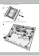


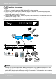

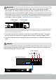

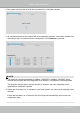
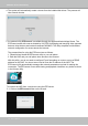
Table Of Contents
- Chapter One Hardware Installation and Initial Configuration
- Section One
- Management over a
- Local Console
- Chapter Two
- Introduction to the Local Console Interface
- Chapter Three
- Configuation Using the Local Console
- The Main Control Portal
- 3-3-1. Basic Search
- 3-3-2. Advanced Search
- 3-3-3. Storyboard
- 3-4-1. Settings - Overview
- 3-4-2. Settings - Camera - Management
- 3-4-3. Settings - Camera - Recording
- 3-4-4. Settings - Camera - Media
- 3-4-5. Settings - Camera - Image
- 3-4-6. Settings - Camera - Motion Detection
- 3-4-7. Settings - Camera - PTZ settings
- 3-4-8. Settings - Alarm - Alarm
- 3-4-9. Settings - Alarm - Email
- 3-4-10. Settings - System - Information
- 3-4-11. Settings - System - Maintenance
- 3-4-12. Settings - System - Display
- 3-4-13. Settings - System - UPS
- 3-4-14. Settings - System - Log
- 3-4-15. Settings - System - EZConnect service
- 3-4-16. Settings - User
- 3-4-17. Settings - Storage
- 3-4-17. Settings - Network
- Settings - Network - IP
- Settings - DDNS
- Settings - Service
- Section Two
- Management over a Web Console
- Chapter Four Login and Getting Started
- Chapter Five System Settings
- Chapter Six Operation
- Technical Specifications
- Safety and Compatibility

VIVOTEK - Built with Reliability
14 - User's Manual
Interface Connections
Although the system supports MAC Binding, the system should be able to detect VIVOTEK's
cameras within the network regardless of the presence of a DHCP server. Ideally, cameras
and the NVR should reside in the same subnet. If a camera's IP is changed for some reasons,
the system should be able to detect its new IP.
NOTE:
1. Connect to a monitor using an HDMI cable. VGA is also supported.
2. Connect CAT5e or better-quality Ethernet cable to IP cameras. The Ethernet ports provide
PoE power. The maximum power per port is 15.4 watts. However, please note that the total
budget is 40 watts by every 4 PoE ports.
3. Connect USB devices such as, mouse, keyboard, USB optical drive, or USB thumb drive (for-
matted in FAT format), or UPS.
4. Connect external devices, such as sensors, relays, or alarms to the terminal block.
5. Connect the power adaptor to the power mains and the system.
3
AC100~240V
50/60Hz, 2-1A
LAN
LAN/WAN
PoE