
User Manual


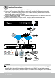

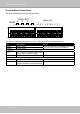

Table Of Contents
- Chapter One Hardware Installation and Initial Configuration
- Section One
- Management over a
- Local Console
- Chapter Two
- Introduction to the Local Console Interface
- Chapter Three
- Configuation Using the Local Console
- The Main Control Portal
- 3-3-1. Basic Search
- 3-3-2. Advanced Search
- 3-3-3. Storyboard
- 3-4-1. Settings - Overview
- 3-4-2. Settings - Camera - Management
- 3-4-3. Settings - Camera - Recording
- 3-4-4. Settings - Camera - Media
- 3-4-5. Settings - Camera - Image
- 3-4-6. Settings - Camera - Motion Detection
- 3-4-7. Settings - Camera - PTZ settings
- 3-4-8. Settings - Alarm - Alarm
- 3-4-9. Settings - Alarm - Email
- 3-4-10. Settings - System - Information
- 3-4-11. Settings - System - Maintenance
- 3-4-12. Settings - System - Display
- 3-4-13. Settings - System - UPS
- 3-4-14. Settings - System - Log
- 3-4-15. Settings - System - EZConnect service
- 3-4-16. Settings - User
- 3-4-17. Settings - Storage
- 3-4-17. Settings - Network
- Settings - Network - IP
- Settings - DDNS
- Settings - Service
- Section Two
- Management over a Web Console
- Chapter Four Login and Getting Started
- Chapter Five System Settings
- Chapter Six Operation
- Technical Specifications
- Safety and Compatibility

VIVOTEK - Built with Reliability
16 - User's Manual
Terminal Block Connections
The terminal block pinouts is shown as follows:
RS485
+-
4 3 2 1
Alarm OUT
G 8 7 6 5 G 4 3 2 1
Alarm IN
DO+DO- DO+DO- DO+DO- DO+DO-
The pins are listed and described from left to right as shown in the drawing above.
Pin Description NOTE
RS485- RS485 Data- A 120Ω terminator is enabled on the bus.
The terminator cannot be disabled.
RS485+ RS485 Data+
Alarm OUT
DO+ DC 12V±5% output, max. 40V,
50mA. Open collector design.
DO- Signal ground
Alarm IN
DI no. 1 ~ 8 Open-short-to-GND
G Pins #1~4 share a common ground.
Pins #5~8 share a common ground.