VIVOTEK Table of Contents Overview ������������������������������������������������������������������������������������������������������������������������������������������������������3 Read before use ��������������������������������������������������������������������������������������������������������������������������������������3 Package contents ������������������������������������������������������������������������������������������������������������������������������������3 Physical Description
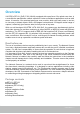
VIVOTEK Overview VIVOTEK’s PZ7131 (PoE) /7132 (WLAN), equipped with a pan-focus 2.6x optical zoom lens, is a cost-effective pan/tilt/zoom network camera for indoor surveillance applications such as retail stores. It houses a 2.6x motorized pan-focus zoom module, which can easily zoom in and out to view near or distant objects. With a 350-degree horizontal and 125-degree vertical range of capture, it effectively gives users a wide, bird’s-eye view of any area.
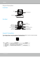
VIVOTEK Physical Description Front Panel Lens Built-in Microphone Status LED Rear Panel Antenna (PZ7132 Only) Microphone In Ethernet 10/100 RJ45 Socket Audio Out Power Cord Socket Mic. In 12VDC Ethernet Ext. I/O Audio Out Ext. Int. General I/O Terminal Block Recessed Reset Button External/Internal Microphone Switch General I/O Terminal Block This Network Camera provides a general I/O terminal block which is used to connect external input / output devices.
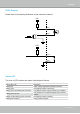
VIVOTEK DI/DO Diagram Please refer to the following illustration for the connection method. 12V PIN 1 Power+12V PIN 2 Digital output +12V PIN 3 Digital input PIN 4 Ground Status LED The color of LED indicates the status of the Network Camera. Status LED Color Description Blinking red Power is being supplied to the Network Camera. Steady green The Network Camera is booting up.
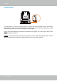
VIVOTEK Hardware Reset Mic. In Ethernet 12VDC Ext. I/O Mic. In 12VDC Ethernet Ext. I/O Audio Out Audio Out Ext. Int. Ext. Int. The reset button is used to reset the system or restore the factory default settings. Sometimes resetting the system can return the camera to normal operation. If the system problems remain after rebooting, restore the factory settings and install again. Reset: Press and release the recessed reset button with a paper clip or thin object.
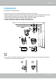
VIVOTEK Installation Hardware Installation Follow the steps below to install the Network Camera to the ceiling: 1. Attach ceiling mount bracket A to the Network Camera and secure it with two small screws. 2. Drill three pilot holes into the ceiling; hammer the plastic anchors into the holes. 3. Fasten ceiling mount bracket B to the ceiling with three screws. 4. Slide the Network Camera into ceiling mount bracket B. 5. Secure ceiling mount bracket A and B with a small screw.
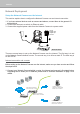
VIVOTEK Network Deployment Setup the Network Camera over the Internet This section explains how to configure the Network Camera over an Internet connection. 1. If you have external devices such as sensors and alarms, connect them to the general I/O terminal block. 2. Connect the camera to a switch via Ethernet cable. 3. Connect the supplied power cable from the Network Camera to a power outlet.
VIVOTEK 2. In this case, if the Local Area Network (LAN) IP address of your Network Camera is 192.168.0.3, please forward the following ports for the Network Camera on the router. ■ HTTP port ■ RTSP port ■ RTP port for audio ■ RTCP port for audio ■ RTP port for video ■ RTCP port for video If you have changed the port numbers on the Network page, please open the ports accordingly on your router. For information on how to forward ports on the router, please refer to your router’s user’s manual. 3.
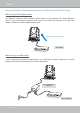
VIVOTEK Set up the Network Camera through Power over Ethernet (PoE) (PZ7131 only) When using a PoE-enabled switch The Network Camera is PoE-compliant, which allows it to be powered via a single Ethernet cable. If your switch/router supports PoE, refer to the following illustration to connect the Network Camera to a PoE-enabled switch/router.
VIVOTEK Set up the Network Camera through Wireless Connection (PZ7132 only) 1. Check the SSID currently set on your wireless access point (AP). 2. Go to PZ7132's Configuration > Advanced mode > Wireless. 3. Type in the SSID consistent with the setting on your AP. 4. Select the Wireless mode as "Infrastructure". 5. Click Save. The Network Camera starts to reboot. 6. Wait for the live image is reloaded to your browser. Then, unplug the power cable and Ethernet cable from the Network Camera. 7.
VIVOTEK Software Installation Installation Wizard 2 (IW2), free-bundled software included on the product CD, helps you set up your Network Camera on the LAN. 1. Install IW2 from the Software Utility directory on the software CD. Double click the IW2 shortcut on your desktop to launch the program. 2. The program will conduct an analysis of your network environment. After your network environment is analyzed, please click Next to continue the program. 3.
VIVOTEK Accessing the Network Camera This chapter explains how to access the Network Camera through web browsers, RTSP players, 3GPP-compatible mobile devices, and VIVOTEK recording software. Using Web Browsers Use Installation Wizard 2 (IW2) to access to the Network Cameras installed on the LAN. If your network environment is not the LAN, follow these steps to access the Network Camera: 1. Launch your web browser (eg. Microsoft® Internet Explorer, Mozilla Firefox, or Netscape). 2.
VIVOTEK ► By default, the Network Camera is not password-protected. To prevent unauthorized access, it is highly recommended to set a password for the Network Camera. For more information about how to enable password protection, please refer to Security on page 27. ► If you see a dialog box indicating that your security settings prohibit running ActiveX ® Controls, please enable the ActiveX ® Controls for your browser. 1. Choose Tools > Internet Options > Security > Custom Level. 2.
VIVOTEK Using RTSP Players To view the MPEG-4 streaming media using RTSP players, you can use one of the following applications that support RTSP streaming. Quick Time Player Real Player VLC media player 1. Launch a RTSP player. mpegable Player 2. Choose File > Open URL. An URL dialog box will pop up. 3.
VIVOTEK Using 3GPP-compatible Mobile Devices To view the streaming media through 3GPP-compatible mobile devices, make sure the Network Camera can be accessed over the Internet. For more information on how to set up the Network Camera over the Internet, please refer to Setup the Network Camera over the Internet on page 8. To utilize this feature, please check the following settings on your Network Camera: 1.
VIVOTEK Using VIVOTEK Recording Software The product software CD also contains VIVOTEK’s recording software, allowing simultaneous monitoring and video recording for multiple Network Cameras. Please install the recording software, then launch the program to add the Network Camera to the Channel list. For detailed information about how to use the recording software, please refer to the user’s manual of the software or download the manual from http://www.vivotek.com.
VIVOTEK Main Page This chapter explains the layout of the main page. It is composed of the following sections: VIVOTEK INC. Logo, Host Name, Camera Control Area, PTZ Control Panel, Configuration Area, and Live video window. Host Name Logo of VIVOTEK INC. Camera Control Area PTZ Control Area Live View Window Configuration Area VIVOTEK INC. Logo Click this logo to visit the VIVOTEK website. Host Name The host name can be customized to fit your needs.
VIVOTEK Pan: Click this button to start the auto pan. When the current position is Home or on the left side of Home, the camera starts panning from the current position to the left-most position, then to the rightmost position, and finally backward to the original position. When the current position is on the right side of Home, the camera starts panning from the current position to the right-most position, then to the leftmost position, and finally backward to the original position.
VIVOTEK Video Title: The video title can be configured. For more information, please refer to Video Settings on page 52. MPEG-4 Protocol and Media Options: The transmission protocol and media options for MPEG-4 video streaming. For further configuration, please refer to Client Settings on page 22. Time: Display the current time. For further configuration, please refer to Video Settings on page 52. Title and Time: The video title and time can be stamped on the streaming video.
VIVOTEK Go to: Once the Administrator has determined the list of preset positions, you can aim the camera using this command. For more information, please refer to Camera Control on page 60. ■ The following window is displayed when the video mode is set to MJPEG: Video Title Title and Time Time Video 13:53:26 2008/12/01 Video Control Buttons Drop-down List of Preset Positions Video Title: The video title can be configured. For more information, please refer to Video Settings on page 52.
VIVOTEK Client Settings This chapter explains how to select the stream transmission mode and saving options on the local computer. When finished with the settings on this page, click Save on the bottom of the page to enable the settings. MPEG-4 Media Options Select whether to stream video or audio data or both. This is enabled only when the video mode is set to MPEG-4.
VIVOTEK MP4 Saving Options Users can record live video as they are watching by clicking Here, you can specify the storage destination and file name. Start MP4 Recording on the main page. Folder: Specify the storage destination for the recorded video files. File name prefix: Enter the text that will be appended to the front of the video file name. Add date and time suffix to the file name: Select this option to append the date and time to the end of the file name.
VIVOTEK Configuration Click Configuration on the main page to enter the camera setting pages. Note that only Administrators can access the configuration page. VIVOTEK offers an easy-to-use user interface that helps you set up your network camera with minimal effort. To simplify the setting procedure, two types of user interfaces are available: Advanced Mode for professional users and Basic Mode for entry-level users.
VIVOTEK Advanced Mode Configuration list Click to switch to Basic mode Firmware Version Each function on the configuration list will be explained in the following sections. Those functions that are displayed only in Advanced Mode are marked with Advanced Mode . If you want to set up the advanced functions, please click [Advanced Mode] on the bottom of the configuration list to quickly switch over.
VIVOTEK System Time Keep current date and time: Select this option to preserve the current date and time of the Network Camera. The Network Camera’s internal real-time clock maintains the date and time even when the system power is turned off. Sync with computer time: Select this option to synchronize the date and time of the Network Camera with the local computer. The read-only date and time of the PC is displayed when updated. Manual: The administrator can enter the date and time manually.
VIVOTEK Security This section explains how to enable password protection and create multiple accounts. Root Password The administrator account name is “root”, which is permanent and can not be deleted. If you want to add more accounts in the Manage User column, please set a password for the “root” account first. 1. Type the password in both text boxes, then click Save to enable password protection. 2.
VIVOTEK HTTPS (Hypertext Transfer Protocol over SSL) Advanced Mode This section explains how to enable authentication and encrypted communication over SSL (Secure Socket Layer). It helps protect streaming data transmission over the Internet on higher security level. Enable HTTPS Check this item to enable HTTPS communication, then select a connection option: "HTTP & HTTPS" or "HTTPS only". Note that you have to create and install a certificate first in the second column before clicking the Save button.
VIVOTEK 4. The Certificate Information will automatically de displayed in the third column as shown below. You can click Property to view detailed information about the certificate. 5. Click Home to return to the main page. Change the address from “http://” to “https://“ in the address bar and press Enter on your keyboard. Some Security Alert dialogs will pop up. Click OK or Yes to enable HTTPS. https:// https://192.168.5.151/index.
VIVOTEK Create self-signed certificate manually 1. Select this option. 2. Click Create to open a Create Certificate page, then click Save to generate the certificate. 3. The Certificate Information will automatically be displayed in the third column as shown below. You can click Property to see detailed information about the certificate. Create certificate and install : Select this option if you want to create an official certificate issued by a CA (Certificate Authority). 1. Select this option. 2.
VIVOTEK 3. If you see the following Information bar, click OK and click on the Information bar on the top of the page to allow pop-ups. 4. The pop-up window shows an example of a certificate request.
VIVOTEK 5. Look for a trusted certificate authority that issues digital certificates. Enroll the Network Camera. Wait for the certificate authority to issue a SSL certificate; click Browse... to search for the issued certificate, then click Upload in the second column. NOTE ► How do I cancel the HTTPS settings? 1. Uncheck Enable HTTPS secure connection in the first column and click Save; a warning dialog will pop up. 2. Click OK to disable HTTPS. 3.
VIVOTEK Network This section explains how to configure a wired network connection for the Network Camera. Network Type LAN Select this option when the Network Camera is deployed on a local area network (LAN) and is intended to be accessed by local computers. The default setting for the Network Type is LAN. Rememer to click Save when you complete the Network setting.
VIVOTEK Network Camera (192.168.5.151) Enable UPnP port forwarding: To access the Network Camera from the Internet, select this option to allow the Network Camera to open ports on the router automatically so that video streams can be sent out from a LAN. To utilize of this feature, make sure that your router supports UPnPTM and it is activated.
VIVOTEK ► Steps to enable UPnP TM user interface on your computer: Note that you must log on to the computer as a system administrator to install the UPnP TM components. 1. Go to Start, click Control Panel, then click Add or Remove Programs. 2. In the Add or Remove Programs dialog box, click Add/Remove Windows Components. 3. In the Windows Components Wizard dialog box, select Networking Services and click Details.
VIVOTEK 4. In the Networking Services dialog box, select Universal Plug and Play and click OK. 5. Click Next in the following window. 6. Click Finish. UPnP TM is enabled. ► How does UPnP TM work? UPnP TM networking technology provides automatic IP configuration and dynamic discovery of devices added to a network. Services and capabilities offered by networked devices, such as printing and file sharing, are available among each other without the need for cumbersome network configuration.
VIVOTEK Enable IPv6 Select this option and click Save to enable IPv6 settings. Please note that this only works if your network environment and hardware equipment support IPv6. The browser should be Microsoft® Internet Explorer 6.5, Mozilla Firefox 3.0 or above. When IPv6 is enabled, by default, the network camera will listen to router advertisements and be assigned with a link-local IPv6 address accordingly. IPv6 Information: Click this button to obtain the IPv6 information as shown below.
VIVOTEK Please follow the steps below to link to an IPv6 address: 1. Open your web browser. 2. Enter the link-global or link-local IPv6 address in the address bar of your web browser. 3. The format should be: http://[2001:0c08:2500:0002:0202:d1ff:fe04:65f4]/ IPv6 address 4. Press Enter on the keyboard or click Refresh button to refresh the webpage.
VIVOTEK HTTP Advanced Mode To utilize HTTP authentication, make sure that your have set a password for the Network Camera first; please refer to Security on page 27 for details. Authentication: Depending on your network security requirements, the Network Camera provides two types of security settings for an HTTP transaction: basic and digest. If basic authentication is selected, the password is sent in plain text format and there can be potential risks of being intercepted.
VIVOTEK URL command -- http://:/ For example, when the Access name for stream 2 is set to video2.mjpg: 1. Launch Mozilla Firefox or Netscape. 2. Type the URL command in the address bar. Press Enter. 3. The JPEG images will be displayed in your web browser. http://192.168.5.151/video2.
VIVOTEK Note that as JPEG only transmits a series of JPEG images to the client, to enable the two-way audio function, make sure the video mode is set to “MPEG-4” on the Audio and Video Settings page and the media option is set to “Video and Audio” on the Client Settings page. Please refer to Client Settings on page 22 and Audio and Video Settings on page 52.
VIVOTEK RTSP Streaming To utilize RTSP streaming authentication, make sure that you have set a password for the Network Camera first; please refer to Security on page 27 for details. Authentication: Depending on your network security requirements, the Network Camera provides three types of security settings for streaming via RTSP protocol: disable, basic, and digest. If basic authentication is selected, the password is sent in plain text format, but there can be potential risks of it being intercepted.
VIVOTEK RTSP port /RTP port for video, audio/ RTCP port for video, audio ■ RTSP (Real-Time Streaming Protocol) controls the delivery of streaming media. By default, the port number is set to 554. ■ The RTP (Real-time Transport Protocol) is used to deliver video and audio data to the clients. By default, the RTP port for video is set to 5556 and the RTP port for audio is set to 5558.
VIVOTEK Wireless LAN (PZ7132 only) SSID (Service Set Identifier): This is the name that identifies a wireless network. Access Points and wireless clients attempting to connect to a specific WLAN (Wireless Local Area Network) must use the same SSID. The default setting is “default”. Note: The maximum length for an SSID is 32 single-byte characters and cannot consist of “, <, >, or blank spaces.
VIVOTEK 2. WEP (Wired Equivalent Privacy): This allows communication only with other devices with identical WEP settings. ■ Authentication Mode: Choose one of the following modes. The default setting is “Open”. Open – Communicates the key across the network. Shared – Allows communication only with other devices with identical WEP settings. ■ Key length: The administrator can set the key length to 64 or 128 bits. The default setting is “64 bits”. ■ Key format: Hexadecimal or ASCII.
VIVOTEK 3. WPA-PSK: Use WPA (Wi-Fi Protected Access) pre-shared key. More secure than WEP, the Wi-Fi Alliance developed WPA (Wi-Fi Protected Access) in 2003 to address WEP’s weaknesses. Improvements included TKIP, which changes the encryption key for each data transmission. ■ Algorithm: Choose one of the following algorithms for WPA-PSK and WPA2-PSK modes. TKIP (Temporal Key Integrity Protocol): A security protocol used in IEEE 802.11 wireless networks.
VIVOTEK DDNS This section explains how to configure the dynamic domain name service for the Network Camera. DDNS is a service that allows your Network Camera, especially when assigned with a dynamic IP address, to have a fixed host and domain name. DDNS: Dynamic domain name service Enable DDNS: Select this option to enable the DDNS setting. Provider: Select a DDNS provider from the provider drop-down list. VIVOTEK offers Safe100.net, a free dynamic domain name service, to VIVOTEK customers.
VIVOTEK [Register] Successfully Your account information has been mailed to registered e-mail address 4. Select Enable DDNS and click Save to enable the setting. ■ CustomSafe100 VIVOTEK offers documents to establish a CustomSafe100 DDNS server for distributors and system integrators. You can use CustomSafe100 to register a dynamic domain name if your distributor or system integrators offer such services. 1. In the DDNS column, select CustomSafe100 from the drop-down list. 2.
VIVOTEK Access List Advanced Mode This section explains how to control access permission by verifying the client PC’s IP address. General Settings Maximum number of concurrent streaming connection(s) limited to: Simultaneous live viewing for 1~10 clients (including stream 1 and stream 2). The default value is 10. If you modify the value and click Save, all current connections will be disconnected and automatically attempt to re-link (IE Explore or Quick Time Player).
VIVOTEK ■ Refresh: Click this button to refresh all current connections. ■ Add to deny list: You can select entries from the Connection Status list and add them to the Deny List to deny access. Please note that those checked connections will only be disconnected temporarily and will automatically try to re-link again (IE Explore or Quick Time Player). If you want to enable the denied list, please check Enable access list filtering and click Save in the first column.
VIVOTEK Network: This rule allows the user to assign a network address and corresponding subnet mask to the Allow/Deny List. For example: IP address 192.168.2.x will be bolcked. Range: This rule allows the user to assign a range of IP addresses to the Allow/Deny List. This rule is only applied to IPv4. For example: ■ Delete Allowed/Denied list: In the Delete Allowed List or Delete Denied List column, make a selection and click Delete.
VIVOTEK Audio and Video This section explains how to cofigure the audio and video settings of the Network Camera. It is composed of the following two columns: Video Settings and Audio Settings. Video Settings Video title: Enter a name that will be displayed on the title bar of the live video. Video title Title and time Video 13:32:09 2008/12/01 Color: Select to display color or black/white video streams.
VIVOTEK Note that when the frame size is set to 176 x 144 as shown in the picture below, only the time will be stamped on the video streams. 12:07:35 2009/04/24 Fix iris Advanced Mode : Select this item to set up the iris at the maximum value; then adjust the zoom factor and focus range. Image Settings Advanced Mode Click Image Settings to open the Image Settings page. On this page, you can tune White balance, Brightness, Saturation, Contrast, and Sharpness for the video.
VIVOTEK ■ Keep current value Follow the steps below to manually set the white balance to compensate for the ambient lighting conditions. 1. Set the White balance to Auto and click Save. 2. Place a sheet of white paper in front of the lens, then allow the Network Camera to adjust the color temperature automatically. 3. Select Keep Current Value to confirm the setting while the white balance is being measured. 4. Click Save to enable the new setting.
VIVOTEK ■ Max gain (Auto Gain Control): You can manually set up the AGC level (4X or 8X). The default value is 4X. ■ Enable BLC (Back Light Compensation): Enable this option when the object is too dark or too bright to recognize. It allows the camera to adjust to the best light conditions in any environment and automatically give the necessary light compensation. You can click Preview to fine-tune the image, or click Restore to recall the original settings without incorporating the changes.
VIVOTEK ■ Video quality A complex scene generally produces larger file size, meaning that higher bandwidth will be needed for data transmission. Therefore, if Constant bit rate is selected, the bandwidth utilization is fixed at a selected level, resulting in mutable video quality performances. The bit rates are selectable at the following rates: 20Kbps, 30Kbps, 40Kbps, 50Kbps, 64Kbps, 128Kbps, 256Kbps, 512Kbps, 768Kbps, 1Mbps, 2Mbps, 3Mbps and 4Mbps.
VIVOTEK Audio Settings Mute: Select this option to disable audio transmission from the Network Camera to all clients. Note that if mute mode is turned on, no audio data will be transmitted even if audio transmission is enabled on the Client Settings page. In that case, the following message is displayed: Internal microphone input gain: Select the gain of the internal audio input according to ambient conditions. Adjust the gain from +21 db (most sensitive) ~ -33 db (least sensitive).
VIVOTEK Motion Detection This section explains how to configure the Network Camera to enable motion detection. A total of three motion detection windows can be configured. Video(TCP-AV) Follow the steps below to enable motion detection: 1. Click New to add a new motion detection window. 2. In the Window Name text box, enter a name for the motion detection window. ■ To move and resize the window, drag and drop your mouse on the window. ■ To delete window, click X on the top right corner of the window. 3.
VIVOTEK A green bar indicates that even though motions have been detected, the event has not been triggered because the image variations still fall under the defined threshold. Percentage = 30% NOTE ► How does motion detection work? A C B D There are two motion detection parameters: Sensitivity and Percentage. In the illustration above, frame A and frame B are two sequential images.
VIVOTEK Camera Control This section explains how to control the Network Camera’s Pan/Tilt/Zoom/Focus operation via the control panel and how to preset positions. Preset Locations On this page, you can preset positions for the Network Camerato go to directly or patrol. A total of 128 preset positions can be configured. Please follow the steps below to preset a position: 1. Adjust the shooting area to a desired position using the buttons on the right side of the window. 2.
VIVOTEK Patrol Settings You can select preset locations for the Network Camera to patrol. Please follow the steps below to set up a patrol schedule: 1. Click a preset location on the list and click Select. 2. The selected preset locations will be displayed on the Selected locations list. 3. Set the Dwelling time for the preset location during auto patrol. The default value is 10 seconds. You can also manually set a value and click Update. 4. Repeat step 1 and 3 to select additional preset locations. 5.
VIVOTEK ■ The Preset Locations will be displayed on the Home page: ■ Click Go to: The Network Camera will move to the preset location. ■ Click Patrol: The Network Camera will patrol among the selected preset positions (from right to left) for once.
VIVOTEK Homepage Layout Advanced Mode This section explains how to set up your own customized homepage layout. Preview This column shows the settings of your homepage layout. You can manually select the background and font colors in Theme Options, the third column on this page. The settings will automatically show up in this Preview field. The following shows the homepage using the default settings: Logo Here you can change the logo at the top of your homepage.
VIVOTEK Theme Options Here you can change the color of your homepage layout. There are three types of preset patterns for you to choose from. The new layout will simultaneously appear in the Preview filed. Click Save to enable the settings.
VIVOTEK ■ Follow the steps below to set up the customed homepage: 1. Click Custom on the left column. 2. Click the field where you want to change the color on the right column. Color Selector Custom Pattern 3. The palette window will pop up as shown below. 2 3 1 4 4. Drag the slider bar and click on the left square to select a desired color. 5. The selected color will show up in the corresponding fields and in the Preview column. 6. Click Save to enable the settings.
VIVOTEK Application Advanced Mode This section explains how to configure the Network Camera to react in response to particular situations (event). A typical application is that when a motion is detected, the Network Camera sends buffered images to a FTP server or e-mail address as notifications. In the illustration on the right, an event can be triggered by many sources, such as motion detection or external digital input devices.
VIVOTEK Event Settings In the Event Settings column, click Add to open the Event Settings page. On this page, you can arrange three elements -- Trigger, Schedule, and Action to set an event. A total of 3 event settings can be configured. Event name: Enter a name for the event setting. Enable this event: Select this option to enable the event setting. Priority: Select the relative importance of this event (High, Normal, or Low). Events with a higher priority setting will be executed first.
VIVOTEK An event is an action initiated by a user-defined trigger source; it is the causal arrangement of the following three elements: Trigger, Event Schedule, and Action. Trigger This is the cause or stimulus which defines when to trigger the Network Camera. The trigger source can be configured to use the Network Camera’s built-in motion detection mechanism or external digital input devices. There are several choices of trigger sources as shown below.
VIVOTEK Event Schedule Specify the period for the event. ■ Select the days of the week. ■ Select the recording schedule in 24-hr time format. Action Define the actions to be performed by the Network Camera when a trigger is activated. ■ Trigger digital output for seconds Select this option to turn on the external digital output device when a trigger is activated. Specify the length of the trigger interval in the text box.
VIVOTEK Here is an example of Event Settings page: When completed, click Save to take effect and then click Close to quit Event Settings page. The new event settings / server settings / media settings will appear in the event drop-down list on the Application page.
VIVOTEK Here is an example of Application page with an event setting: When the Event Status is ON, once an event is triggered by motion detection, the Network Camera will automatically send snapshots via e-mail. If you want to stop the event trigger, you can click ON to turn it to OFF status or click Delete to remove the event setting. To remove a server setting from the list, select a server name from the drop-down list and click Delete.
VIVOTEK Server Settings Click Add Server on Event Settings page to open the Server Setting page. On this page, you can specify where the notification messages are sent when a trigger is activated. A total of 5 server settings can be configured. Server name: Enter a name for the server setting. Server Type There are four choices of server types available: Email, FTP, HTTP, and Network storage. Select the item to display the detailed configuration options. You can configure either one or all of them.
VIVOTEK FTP: Select to send the media files to an FTP server when a trigger is activated. ■ Server address: Enter the domain name or IP address of the FTP server. ■ Server port By default, the FTP server port is set to 21. It can also be assigned to another port number between 1025 and 65535. ■ User name: Enter the login name of the FTP account. ■ Password: Enter the password of the FTP account. ■ FTP folder name Enter the folder where the media file will be placed.
VIVOTEK HTTP: Select to send the media files to an HTTP server when a trigger is activated. ■ URL: Enter the URL of the HTTP server. ■ User name: Enter the user name if necessary. ■ Password: Enter the password if necessary. To verify if the HTTP settings are correctly configured, click Test. The result will be shown in a pop-up window as below. If successful, you will receive a test.txt file on the HTTP server. Click Save to enable the settings, then click Close to exit the page.
VIVOTEK Media Settings Click Add Media on the Event Settings page to open the Media Settings page. On this page, you can specify the type of media that will be sent when a trigger is activated. A total of 5 media settings can be configured. Media name: Enter a name for the media setting. Media Type There are three choices of media types available: Snapshot, Video clip, and System log. Select the item to display the detailed configuration options. You can configure either one or all of them.
VIVOTEK Video clip: Select to send video clips when a trigger is activated. ■ Source: Select to record video clips from stream 1 or stream 2. ■ Pre-event recording The Network Camera has a buffer area; it temporarily holds data up to a certain limit. Enter a number to decide the duration of recording before a trigger is activated. Up to 9 seconds can be set. ■ Maximum duration Specify the maximum recording duration in seconds. Up to 10 seconds can be set.
VIVOTEK Recording notify message: Select to send a recording notification message when a trigger is activated. The following is an example of a recording notification message (.txt file), which shows a list of deleted previously-recorded data due to cycle recording. When completed, click Save to enable the settings and click Close to exit this page. The new media settings will appear on the Event Settings page. You can continue to select a server and media type for the event.
VIVOTEK Click 20081120 to open the directory: The format is: HH (24r) Click to open the file list of that hour Click to go back to the previous level of the directory Click to delete selected items Click to delete all recorded data The format is: File name prefix + Minute (mm) You can set up the file name prefix on Media Settings page. Please refer to page 75 for detailed information.
VIVOTEK Recording Advanced Mode This section explains how to configure the recording settings for the Network Camera. Recording Settings NOTE ► Before setting up this page, please set up the Network Storage on the Server Settings page first. Network Storage Setting Click Server to open the Server Settings page and follow the steps below to set up: 1. Fill in the information for your server.
VIVOTEK If successful, you will receive a test.txt file on the network storage server. 3. Enter a server name. 4. Click Save to complete the settings and click Close to exit the page. Recording Settings Click Add to open the recording setting page. On this page, you can define the recording source, recording schedule and recording capacity. A total of 2 recording settings can be configured.
VIVOTEK Recording name: Enter a name for the recording setting. Enable this recording: Select this option to enable video recording. Priority: Select the relative importance of the recording setting (High, Normal, and Low). Source: Select the recording source (stream 1 or stream 2). Recording Schedule: Specify the recording duration. ■ Select the days of the week. ■ Select the recording start and end times in 24-hr time format.
VIVOTEK System Log Advanced Mode This section explains how to configure the Network Camera to send the system log to the remote server as backup. Remote Log You can configure the Network Camera to send the system log file to a remote server as a log backup. Before utilizing this feature, it is suggested that the user install a log-recording tool to receive system log messages from the Network Camera. An example is Kiwi Syslog Daemon. Visit http://www.kiwisyslog. com/kiwi-syslog-daemon-overview/.
VIVOTEK View Parameters Advanced Mode The View Parameters page lists the entire system’s parameters in alphabetical order. If you need technical assistance, please provide the information listed on this page.
VIVOTEK Maintenance This chapter explains how to restore the Network Camera to factory default, upgrade firmware version, etc. Reboot This feature allows you to reboot the Network Camera, which takes about one minute to complete. When completed, the live video page will be displayed in your browser. The following message will be displayed during the rebooting process.
VIVOTEK Calibrate This feature re-calibrate the home position to the default center to recover the any displacement caused by external forces. Please note that there is no confirm message box after clicking on Calibrate, and the Network Camera will calibrate immediately. Export / Upload Files Advanced Mode This feature allows you to Export / Upload daylight saving time rules, custom language files, and setting backup files.
VIVOTEK Upload daylight saving time rule: Click Browse… and specify the XML file to upload. If the incorrect date and time are assigned, you will see the following warning message when uploading the file to the Network Camera. The following message is displayed when attempting to upload an incorrect file format. Export language file: Click to export language strings. VIVOTEK provides nine languages: English, Deutsch, Español, Français, Italiano, 日本語, Português, 簡体中文, and 繁體中文.
VIVOTEK Upgrade Firmware This feature allows you to upgrade the firmware of your Network Camera. It takes a few minutes to complete the process. Note: Do do not power off the Network Camera during the upgrade! Follow the steps below to upgrade the firmware: 1. Download the latest firmware file from the VIVOTEK website. The file is in .pkg file format. 2. Click Browse… and specify the firmware file. 3. Click Upgrade.
VIVOTEK Appendix URL Commands for the Network Camera Overview For some customers who already have their own web site or web control application, the Network Camera/Video Server can be easily integrated through URL syntax. This section specifies the external HTTP-based application programming interface. The HTTP-based camera interface provides the functionality to request a single image, control camera functions (PTZ, output relay etc.), and get and set internal parameter values.
VIVOTEK General CGI URL syntax and parameters CGI parameters are written in lower-case and as one word without any underscores or other separators. When the CGI request includes internal camera parameters, the internal parameters must be written exactly as they are named in the camera or video server. The CGIs are organized in function related directories under the cgi-bin directory. The file extension of the CGI is required. Syntax: http:///cgi-bin/[/...]/.
VIVOTEK http:///cgi-bin/viewer/getparam.cgi?[] [&…] http:///cgi-bin/operator/getparam.cgi?[] [&…] http:///cgi-bin/admin/getparam.cgi?[] [&…] where the should be [_] or [.] If you do not specify the any parameters, all the parameters on the server will be returned. If you specify only , the parameters of related group will be returned.
VIVOTEK Set server parameter values Note: The access right depends on the URL directory. Method: GET/POST Syntax: http:///cgi-bin/anonymous/setparam.cgi? = [&=…][&update=][&return=] http:///cgi-bin/viewer/setparam.cgi? = [&=…][&update=] [&return=] http:///cgi-bin/operator/setparam.
VIVOTEK \r\n where is =\r\n [] Only the parameters that you set and readable will be returned. Example: Set the IP address of server to 192.168.0.123 Request: http://myserver/cgi-bin/admin/setparam.cgi?network_ipaddress=192.168.0.123 Response: HTTP/1.0 200 OK\r\n Content-Type: text/html\r\n Context-Length: 33\r\n \r\n network.ipaddress=192.168.0.
VIVOTEK , … blank A blank string everything inside <> As description NOTE: The camera should prevent to restart when parameter changed. Group: system NAME VALUE SECURITY DESCRIPTION (get/set) hostname string[40] 1/6 host name of server (Network Camera, Wireless Network Camera) ledoff 6/6 turn on(0) or turn off(1) all led indicators date , 6/6 Current date of system. Set to ‘keep’ time keep, keeping date unchanged.
VIVOTEK Indiana -160: GMT-04:00 Atlantic Time, Canada, Caracas, La Paz, Santiago -140: GMT-03:30 Newfoundland -120: GMT-03:00 Brasilia, Buenos Aires, Georgetown, Greenland -80: GMT-02:00 Mid-Atlantic -40: GMT-01:00 Azores, Cape_Verde_IS.
VIVOTEK Seoul, Yakutsk 380: GMT 09:30 Adelaide, Darwin 400: GMT 10:00 Brisbane, Canberra, Melbourne, Sydney, Guam, Vladivostok 440: GMT 11:00 Magadan, Solomon Is., New Caledonia 480: GMT 12:00 Aucklan, Wellington, Fiji, Kamchatka, Marshall Is. 520: GMT 13:00 Nuku'Alofa daylight_enable 6/6 enable automatic daylight saving to time zone daylight_dstactual 6/7 mode daylight_auto_beg check if current time is under daylight saving time.
VIVOTEK settings. This command can cooperate with other “restoreexceptXYZ” commands. When cooperating with others, the system parameters will be restored to default value except a union of combined results. restoreexceptlang 7/6 Restore the system parameters to default value except custom language file user uploaded. This command can cooperate with other “restoreexceptXYZ” commands.
VIVOTEK Group: status NAME VALUE SECURITY DESCRIPTION (get/set) di_i<0~(ndi-1)> 1/7 0 => Inactive, normal 1 => Active, triggered do_i<0~ndi-1)> 1/7 0 => Inactive, normal 1 => Active, triggered onlinenum_rtsp integer 6/7 current RTSP connection numbers onlinenum_httppush integer 6/7 current HTTP push server connection numbers Group: di_i<0~(ndi-1)> (capability.
VIVOTEK Group: network NAME VALUE SECURITY DESCRIPTION (get/set) type lan, 6/6 Network connection type 6/6 1 => get ipaddress, subnet, router, dns1, dns2 from pppoe resetip DHCP server at next reboot 0 => use preset ipaddress, subnet, rounter, dns1, and dns2 ipaddress 6/6 IP address of server subnet 6/6 subnet mask router 6/6 default gateway dns1 6/6 primary DNS server dns2 6/6 secondary DNS server wi
VIVOTEK digest s0_accessname string[32] 1/6 Http server push access name for stream 1 (capability.protocol.spush_mjpeg =1 and video.stream.count>0) s1_accessname string[32] 1/6 Http server push access name for stream 2 (capability.protocol.spush_mjpeg =1 and video.stream.count>1) anonymousviewing 1/6 Enable anoymous streaming viewing.
VIVOTEK Subgroup of rtsp_s<0~(n-1)>: multicast, n is stream count (capability.protocol.rtp.
VIVOTEK Adhoc channel txrate 1~11 Infra: Infrastructure or 6/6 USA and Canada 1 ~ 13 or Europe 10~11 or Spain 10~13 or France 1~14 All NONE, 1M, 2M, 6/6 Maximum ٛ ooleanٛ rate in Mbps 6/6 encryption method (product depedent) 5.
VIVOTEK Group: ipfilter NAME VALUE SECURITY DESCRIPTION (get/set) enable 6/6 Enable or disable ipfilter settings admin_enable 6/6 Enable or disable the function always allow the admin IP address to access this device admin_ip 1.0.0.0 ~ 6/6 255.255.255.255 maxconnection 0~10 Always allow this IP connect to camera when admin_enable=1 6/6 Maximum number of concurrent streaming connection(s) limit allow_i<0~9>_start 1.0.0.
VIVOTEK Group: videoin_c<0~(n-1)> for n channel products, m is stream number NAME VALUE SECURITY DESCRIPTION (get/set) color 0, 1 4/4 0 =>monochrome 1 => color flip 4/4 flip the image mirror 4/4 mirror the image text string[16] 1/4 enclosed caption imprinttimestamp 4/4 Overlay time stamp on video maxexposure 1~120 4/4 Maximum exposure time options quality, 4/4 To customize video quality first or video framerate frame rate first.
VIVOTEK s<0~(m-1)>_mjpeg_quant 0~5 4/4 quality of jpeg video. 0 is customized manual input setting. 1 is worst quality and 5 is the best quality. s<0~(m-1)>_mjpeg_ 10~200 7/4 qvalue The specific quality parameter of jpeg encoder. 10 is best quality and 200 is the worst quality. s<0~(m-1)>_mjpeg_maxfr 1~30 4/4 ame s<0~(m-1)>_forcei set maximum frame rate in fps (for JPEG) 1 7/6 Force I frame Group: audioin_c<0~(n-1)> for n channel products (capability.
VIVOTEK Group: image_c<0~(n-1)> for n channel products NAME VALUE SECURITY DESCRIPTION (get/set) brightness -5 ~ 5 4/4 Adjust brightness of image according to mode settings. saturation -5 ~ 5 4/4 Adjust saturation of image according to mode settings. contrast -5 ~ 5 4/4 Adjust contrast of image according to mode settings. sharpness -3 ~ 3 4/4 Adjust sharpness of image according to mode settings.
VIVOTEK win_i<0~2>_objsize 0 ~ 100 4/4 Percent of motion detection window. win_i<0~2>_sensitivity 0 ~ 100 4/4 Sensitivity of motion detection window. Group: ddns NAME VALUE SECURITY DESCRIPTION (get/set) enable 6/6 Enable or disable the dynamic dns. provider Safe100, 6/6 Safe100 => safe100.net DyndnsDynamic, DyndnsDynamic => dyndns.org (dynamic) DyndnsCustom, DyndnsCustom => dyndns.org (custom) TZO, TZO => tzo.com DHS, DHS => dhs.
VIVOTEK Group: syslog NAME VALUE SECURITY DESCRIPTION (get/set) enableremotelog 6/6 enable remote log serverip 6/6 Log server IP address serverport 514, 6/6 Server port used for log 6/6 The levels to distinguish the importance of 1025~65535 level 0~7 information. 0: LOG_EMERG 1: LOG_ALERT 2: LOG_CRIT 3: LOG_ERR 4: LOG_WARNING 5: LOG_NOTICE 6: LOG_INFO 7: LOG_DEBUG Group: camctrl_c<0~(n-1)> for n channel product (capability.
VIVOTEK patrol_i<0~39>_ 0 ~ 999 1/4 Time to dwelling of patrol location dwelling Group: layout NAME VALUE SECURITY DESCRIPTION (get/set) logo_default 1/6 0 => Custom logo 1 => Default logo logo_link string[40] 1/6 Hyperlink of the logo theme_option 1~4 1/6 1~3: One of the default themes 4: Custom definition theme_color_font string[7] 1/6 Font color theme_color_configfont string[7] 1/6 Font color of configuration area theme_color_titlefont string[7] 1/6 Font color o
VIVOTEK naudioout 0, 0/7 number of audio output nvideoin 0/7 number of video input nmediastream 0/7 number of media stream per channel nvideosetting 0/7 number of video settings per channel naudiosetting 0/7 number of audio settings per channel nuart 0, 0/7 number of UART interface 0/7 An 32-bits integer, each bit can be set separately ptzenabled < positive integer >
VIVOTEK Bit 2 => External or build-in pan function. 0(build-in), 1(external) lens_tilt 0/7 An 32-bits integer, each bit can be set separately as follows: Bit 0 => support tilt Bit 1 => support tilt in UI Bit 2 => External or build-in tilt function. 0(build-in), 1(external) lens_zoom 0/7 An 32-bits integer, each bit can be set separately as follows: Bit 0 => support zoom Bit 1 => support zoom in UI Bit 2 => External or build-in zoom function.
VIVOTEK protocol_rtp_multi 0/7 cast_ indicate whether to support backchannel multicast backchannel protocol_rtp_tcp 0/7 indicate whether to support rtp over tcp protocol_rtp_http 0/7 indicate whether to support rtp over http protocol_spush_m 0/7 indicate whether to support server push motion jpeg jpeg protocol_snmp 0/7 indicate whether to support snmp videoin_type 0, 1, 2 0/7 0 => Interlaced CCD 1 => Progressive CCD 2 => CMOS vide
VIVOTEK available codec types separaters by comma) uart_httptunnel 0/7 Indicate whether to support the http tunnel for uart transfer camctrl_privilege 0/7 Indicate whether to support “Manage Privilege” of PTZ control in Security page transmission_mod Tx, 0/7 Indicate what kind of transmission mode the e Rx, machine used. TX: server, Rx: receiver box, Both Both: DVR?.
VIVOTEK priority 0, 1, 2 6/6 Indicate the priority of this event. “0” indicates low priority. “1” indicates normal priority. “2” indicates high priority. delay 1~999 6/6 Delay seconds before detect next event. trigger boot, 6/6 Indicate the trigger condition. di, “boot” indicates system boot. motion, “di” indicates digital input. seq, “motion” indicates video motion detection. “seq” indicates periodic condition di 6/6 Indicate which di detected.
VIVOTEK action_do_i<0~(ndo-1) 0, 1 6/6 To enable or disable trigger digital output. 1~999 6/6 The duration of digital output is triggered in >_enable action_do_i<0~(ndo-1) >_duration seconds. action_goto_enable 0,1 6/6 To enable or disable event goto function action_goto_name string[40] 6/6 The selected name of preset positions 6/6 To enable or disable this server action. action_server_i<0~4>_e 0, 1 nable The default value is 0.
VIVOTEK email_sslmode 0, 1 6/6 Enable support SSL email_port 0~65535 6/6 The port to connect the server. email_passwd string[64] 6/6 The password of the user. email_senderemail string[128] 6/6 The email address of sender. email_recipientemail string[128] 6/6 The email address of recipient. ns_location string[128] 6/6 The location to upload or store the media. ns_username string[64] 6/6 The username to login in the server. ns_passwd string[64] 6/6 The password of the user.
VIVOTEK Group: recording_i<0~1> PARAMETER VALUE SECURITY DESCRIPTION (get/set) name string[40] 6/6 The identification of this entry enable 0, 1 6/6 To enable or disable this recoding. priority 0, 1, 2 6/6 Indicate the priority of this recoding. “0” indicates low priority. “1” indicates normal priority. “2” indicates high priority. source 6/6 Indicate the source of media stream. 0 means the first stream. 1 means the second stream and etc.
VIVOTEK notifyserver 0~31 6/6 Indicate which notification server is scheduled. One bit represents one application server (server_i0~i4). The bit0 (LSB) indicates server_i0. The bit1 indicates server_i1. The bit2 indicates server_i2. The bit3 indicates server_i3. The bit4 indicates server_i4. For example, enable server_i0, server_i2 and server_i4 to be notification server. The notifyserver value is 21. reserveamount 15~ 6/6 The reserve amount in Mbytes when choose cyclic recording mechanism.
VIVOTEK 1=>active countryname string[2] 6/6 country name in certificate information stateorprovincena string[128] 6/6 state or province name in in certificate me information localityname string[128] 6/6 the locality name in certificate information organizationname string[64] 6/6 organization naem in certificate information unit string[32] 6/6 organizational unit name in certificate information commonname string[64] 6/6 common name in certificate information validdays 0 ~ 9999 6/
VIVOTEK Syntax: http:///cgi-bin/dido/getdi.cgi?[di0][&di1][&di2][&di3] If no parameter is specified, all the status of digital input will be returned. Return: HTTP/1.0 200 OK\r\n Content-Type: text/plain\r\n Content-Length: \r\n \r\n [di0=]\r\n [di1=]\r\n [di2=]\r\n [di3=]\r\n where can be 0 or 1. Example: Query the status of digital input 1 Request: http://myserver/cgi-bin/dido/getdi.cgi?di1 Response: HTTP/1.
VIVOTEK Return: HTTP/1.0 200 OK\r\n Content-Type: text/plain\r\n Content-Length: \r\n \r\n [do0=]\r\n [do1=]\r\n [do2=]\r\n [do3=]\r\n where can be 0 or 1. Example: Query the status of digital output 1 Request: http://myserver/cgi-bin/dido/getdo.cgi?do1 Response: HTTP/1.
VIVOTEK Server will return the most up-to-date snapshot of selected channel and stream in JPEG format. The size and quality of image will be set according to the video settings on the server. Return: HTTP/1.0 200 OK\r\n Content-Type: image/jpeg\r\n [Content-Length: \r\n] Account management Note: This request requires administrator privilege Method: GET/POST Syntax: http:///cgi-bin/admin/editaccount.
VIVOTEK return Redirect to the page after the parameter is assigned. The can be a full URL path or relative path according to the current path. If you omit this parameter, it will redirect to an empty page. System logs Note: This request require administrator privilege Method: GET/POST Syntax: http:///cgi-bin/admin/syslog.cgi Server will return the up-to-date system log. Return: HTTP/1.
VIVOTEK Camera Control Note: This request requires privilege of viewer Method: GET/POST Syntax: http:///cgi-bin/camctrl/camctrl.
VIVOTEK vy vs 0~7 Set the speed of movement, “0” means stop. return Redirect to the page after the parameter is assigned. The can be a full URL path or relative path according to the current path. If you omit this parameter, it will redirect to an empty page. Recall Note: This request requires privilege of viewer Method: GET Syntax: http:///cgi-bin/camctrl/recall.
VIVOTEK Return: HTTP/1.0 200 OK\r\n Content-Type: text/plain\r\n Content-Length: \r\n \r\n Model=\r\n CapVersion=0200\r\n PARAMETER(supported VALUE DESCRIPTION system.firmwareversion Model name of server.
VIVOTEK IP filtering Note: This request requires administrator access privilege Method: GET/POST Syntax: http:///cgi-bin/admin/ipfilter.cgi? method=&[start=&end=][&index=] [&return=] PARAMETER VALUE DESCRIPTION Method addallow Add a set of allow IP address range to server. Start and end parameters must be specified. If the index parameter is specified, it will try to add starting from index position.
VIVOTEK Get SDP of Streamings Note: This request requires viewer access privilege Method: GET/POST Syntax: http:///_accessname> “m” is the stream number. “network_accessname_<0~(m-1)>” is the accessname for stream “1” to stream “m”. Please refer to the “subgroup of network: rtsp” for setting the accessname of SDP. You can get the SDP by HTTP GET method.
VIVOTEK Ver 0�1 Technical Specifications Specifications System .CPU: VVTK-1000 SoC .Flash: 8 MB .RAM: 64 MB .Embedded OS: Linux 2.4 Pan/Tilt/Zoom .Pan range: 350° (+175° ~ -175° ) .Tilt range: 125° (+90° ~ -35° ) .2.6x optical zoom .Auto pan mode .Auto patrol mode Lens .Board lens, 2.6x optical zoom, f=2.8 ~ 7.3 mm, F1.9, auto-iris,focus range: 0.75 mm to infinity Angle of View .28.7° ~ 73.4° (horizontal) .21.6° ~ 54.7° (vertical) .35.8° ~ 92.2° (diagonal) Shutter Time .1/5 sec. to 1/15,000 sec.
VIVOTEK Technology License Notice MPEG-4 AAC Technology THIS PRODUCT IS LICENSED UNDER THE MPEG-4 AAC AUDIO PATENT LICENSE. THIS PRODUCT MAY NOT BE DECOMPILED, REVERSE-ENGINEERED OR COPIED, EXCEPT WITH REGARD TO PC SOFTWARE, OF WHICH YOU MAY MAKE SINGLE COPIES FOR ARCHIVAL PURPOSES. FOR MORE INFORMATION, PLEASE REFER TO HTTP://WWW.VIALICENSING.COM.
VIVOTEK Electromagnetic Compatibility (EMC) FCC Statement This device compiles with FCC Rules Part 15. Operation is subject to the following two conditions. ■ This device may not cause harmful interference, and ■ This device must accept any interference received, including interference that may cause undesired operation. This equipment has been tested and found to comply with the limits for a Class B digital device, pursuant to Part 15 of the FCC Rules.