Product name: Video Receiver (RX7101) Release Date: 2009/3/26 Manual Revision: 2.1 Web site: www.vivotek.com Email: technical@vivotek.com sales@vivotek.com Made in Taiwan. ©Copyright 2000-2009. All rights reserved -1www.vivotek.
Before You Use This Product The use of surveillance devices may be prohibited by law in your country. It is the user’s responsibility to ensure that the operation of such devices is legal before installing this unit for its intended use. It is important to first verify that all contents received are complete according to the list in the "Package Contents" chapter.
Table of Contents Before You Use This Product......................................................................2 Package Contents ....................................................................................5 Installation .............................................................................................6 Physical Description............................................................................6 Front Panel ..........................................................................
Viewing system parameters............................................................... 33 Maintenance.................................................................................... 34 Language........................................................................................ 35 Appendix.............................................................................................. 36 A. Troubleshooting ........................................................................... 36 Status LED ......
Package Contents RX7101 Software CD Power adapter Quick installation guide Terminal connector Warranty card -5www.vivotek.
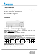
Installation The Video Receiver only supports one privileged account to access and configure it. In this manual, "Administrator" refers to the person. Physical Description Front Panel “Status LEDs” Two LEDs show the status of Video Receiver. Please refer to the Appendix Troubleshooting for details. “Talk” The button is reserved to support two way audio.
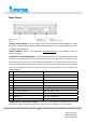
Rear Panel “Power cord socket” Plug the power jack of the included power adapter to Video Receiver. Connecting the power adapter should be the last operation while physically installing Video Receiver. “Reset button” Refer to the Appendix Troubleshooting for the detailed usage of system recovery. “General I/O terminal block” Video Receiver provides a very flexible general I/O interface to combine with the user’s security devices such as alarms, lighting or door locks.
Hardware Installation Please verify that your product package contains all the accessories listed in the foregoing Package Contents. Depending on the user’s application, an Ethernet cable may be needed. The Ethernet cable should meet the specs of UTP Category 5 and not exceed 100 meters in length. Connect the power adapter jack to the Video Receiver before plugging in to the power socket. This will reduce the risk of accidental electric shock. Shut down all the peripheral devices prior to connection.
The Video Receiver will first detect Ethernet. If it does not connect to Ethernet, the system booting will fail. Please connect the Ethernet cable and power on again. When system boot up, the green LED will flash every second as heartbeat to indicate alive. If the green LED is off, please check the network connections. When system is alive, go to next paragraph “Software installation”.
Initial Access to the Video Receiver Check Network Settings The Video Receiver can be connected either before or immediately after software installation onto the Local Area Network. The Administrator should complete the network settings on the configuration page, including the correct subnet mask and IP address of gateway and DNS. Ask your network administrator or Internet service provider for the detail information.
How to Use Authentication After opening the Web browser and typing in the URL of the Video Receiver, a dialogue window pops up to request a username and password. Upon successful authentication, the following figure is displayed. The foreground is the login window and the background shows the message if authentication fails. The option box can be checked to save the password for future convenience. But it is not available to the Administrator for obvious reason.
Main Page This chapter explains the layout of the main page. It is composed of the following four sections: Logo of VIVOTEK INC., Menu, Host name, and information of Overview. Video Receiver supports maximum twenty video sources. The display mode can be single channel and multiple channels. And the multiple channel display can display four channels simultaneously or twenty-channel sequentially. In sequential mode the period of showing a channel can be adjusted.
Primary capability of Video Receiver Video The Video Receiver supports maximum twenty video sources. The display mode can be single channel and multiple channels. And the multiple channel display can be display four channels simultaneously or twenty-channel sequentially. In sequential mode the period of showing a channel can be adjusted. When single channel mode is selected, only channel 1 is effective.
OSD (On Screen Display) The Video Receiver provides the following information for showing the connection or display status. If the IP address is empty, the video output shows "No Video" on the top-right corner. If the IP address is configured but the channel is disconnected, the video output shows the IP address on the top-right corner. In sequential multi-channel mode, if the periodic channel switch is stopped, there should be a channel ID on the top-right corner. - 14 www.vivotek.
Definitions in Configuration The Administrator can access system configuration. Each category in the left column will be explained in the following pages. The bold texts are the specific phrases on the Option pages. The Administrator may type the URL below the figure to directly enter the frame page of configuration. If the Administrator also wants to set certain options through the URL, read the reference appendix for details.
If the “Multiple channel mode” is selected, it will show the information of four channels. Please refer to “Video source” setting for detailed information. - 16 www.vivotek.
System settings "Host name" The text displays the title at the top of the banner. "Keep current date and time" Click on this to reserve the current date and time of the Video Receiver. An internal real-time clock maintains the date and time even when the power of the system is turned off. "Sync with computer time" Synchronizes the date and time of the Video Receiver with the local computer. The read-only date and time of the PC is displayed as updated.
Video source settings There are three parts of video source settings: “Mode”, “Video source list”, and “Display list”. - 18 www.vivotek.
"Mode" Select “Single channel mode”, or “multiple channel mode” which you want to display on the TV or monitor. The multiple channel mode can display four channels simultaneously (Quad display) or twenty-channel sequentially (Sequential display). “Video source list” To manage the video source list. “Auto detection” click this button to search for all detected sources in the same LAN. - 19 www.vivotek.
Select one of sources and click “Select” to configure it. Enter a descriptive Name for the video source, choose either Stream 1 or Stream 2 as the source, and enter the User name and Password if necessary. There are four types for RTSP streaming: Multicast, UDP, TCP and HTTP. Video and audio can be chosen independently. If you want to Use HTTP proxy, configure it first in the Network Settings page. Remember to click “Save” to enable the source settings. - 20 www.vivotek.
“Create” click this button if you would like to manually set up the source information. Remember to click “Save” to enable the source settings. - 21 www.vivotek.
Click “Close” to quit the Video information page. The video sources will be displayed in the column of video source list. For example: “Modify” Select a video source from the list and then click this button to open the Video source settings page. Remember to click “Save” after adding modification. “Delete” Select a video source from the list and then click this button to delete it. “Information” Select a video source from the list and then click this button to open the Video information window. - 22 www.
“Add to display list” Click this button to add video sources to the Display list according to the Display Mode selected in the first column. "Single channel mode" You can only add one video source to the Display list, and the Video Receiver will show only one channel in video output. The video resolution can be set up to D1. Remember to click “Save” to enable the source settings. For example: - 23 www.vivotek.
"Multiple channel mode" The multiple channel mode can display four channels simultaneously (Quad display) or twenty-channel sequentially (Sequential display) on the analog video devices. "Sequential display" You can add up to 20 video sources to the Display list, and the video receiver will shows Channel 1, 2, 3, 4…in order with D1 resolution. Enter a “Channel switch period” for the sequential display.
"Quad display" You can add up to 4 video sources to the Display list, and the video receiver will show four channels at the same time. The maximum video resolution will be limited to CIF. - 25 www.vivotek.
Security settings “Root password” Change the Administrator’s password by typing in the new password identically in both text boxes. The typed entries will be displayed as asterisks for security purposes. http://
Network settings Any changes made on this page will restart the system in order to validate the changes. Make sure every field is entered correctly before clicking on . Network type “LAN” & “PPPoE” The default type is LAN. Select PPPoE if using ADSL "Get IP address automatically" & “Use fixed IP address” The default status is “Get IP address automatically”. This can be tedious having to perform software installation whenever the Video Receiver starts.
HTTP “Http port” This can be other than the default Port 80. Once the port is changed, the users must be notified the change for the connection to be successful. For instance, when the Administrator changes the HTTP port of the Video Receiver whose IP address is 192.168.0.100 from 80 to 8080, the users must type in the web browser “http://192.168.0.100:8080” instead of “http://192.168.0.100”. “Http proxy setting” If your network need to configure Http proxy, please enter related information in the blanks.
Email settings When the SMTP server support SMTP authentication, users need to give the valid user name and password to send email via the server. There are two external mail server can be configured, primary and secondary email server, The Video Receiver will use primary server as default , and use secondary server when primary server is unreachable. “Server address” The domain name or IP address of the external email server. “User name” This granted user name on the external email server.
I/O settings Video output Video output modulation type. It can be “NTSC” or “PAL”. “Enable Overscan mode” Select it if you has smaller displayable area of your device. Audio output The audio output volume can be tuned in Video Receiver. Digital output Video Receiver supports four digital outputs, and they can be configured to follow the digital output of video source. This function is only for “Single channel mode” and “Quad display mode”. “Sequential display mode” does not support this function.
Keyboard The keyboard can be connected with Video Receiver via RS485 interface. The following fields in Video Receiver must be set the same with the keyboard. “Baud rate” The transmission speed between Video Receiver and keyboard “Data bits” The length of a data “Stop bits” The length of stop bit “Parity bits” The type of parity check - 31 www.vivotek.
System log The Video Receiver is able to send system log to the remote server as a backup. The protocol is compliant to RFC 3164. If you have external Linux server with “syslogd” service, use “-r” option to turn on the facility for receiving log from remote machine. Or you can use some software on Windows which is compliant to RFC 3164. Check “Enable remote log” and input the “IP address” and “port” number of the log server to enable the remote log facility.
Viewing system parameters The View parameters page lists the entire system’s parameters in alphabetical order. If you need technical assistance, please provide the information listed in this page. - 33 www.vivotek.
Maintenance Three actions can be selected “Reboot system” To turn off and then turn on the Video Receiver. It takes about one ~ two minutes to complete the process. “Factory default” To restore the factory default settings. Any changes made so far will be lost and the system will be reset to the initial factory settings. The system will restart and require the installer program to set up the network again. “Upgrade firmware” To upgrade the firmware on your Video receiver.
Language Click this button to choose a language for the user interface. Language options are available In the following list: - 35 www.vivotek.
Appendix A. Troubleshooting Status LED The following table lists the LED patterns in all cases. The priority 1 is the highest priority. If there are multiple statuses at the same time, the Video Receiver will show the highest priority one. 1 2 LED status Description Priority Steady Red Power on and system booting 5 Red LED unlighted Power off Steady Red + Blink Green every 1 Network works(heartbeat) 4 sec.
Reset and restore There is a button in the back side of the Video Receiver. It is used to reset the system or restore the factory default settings. RESET: Click on the button. RESTORE: 1. Press on the button continuously. 2. Wait for all LED blink fast. 3. Free the button. Restoring the factory defaults will erase any previous settings. B.
Get server parameter values Note: This request require administrator access Method: GET/POST Syntax: http:///cgi-bin/admin/getparam.cgi?[] [&…] Where the should be [_][_] If you do not specify the any parameters, all the parameters on the server will be returned. If you specify only , the parameters of related group will be returned. There may be none or multiple subgroups between group and subgroup.
HTTP/1.0 200 OK\r\n Content-Type: text/html\r\n Context-Length: 33\r\n \r\n network.ipaddress=192.168.0.123\r\n Set server parameter values Note: This request require administrator access Method: GET/POST Syntax: http:///cgi-bin/admin/setparam.cgi? [nosync=&]= [&=…][&return=] parameter value description [_]_. _.
Content-Type: text/html\r\n Context-Length: \r\n \r\n where is =\r\n [] Only the parameters that you set and readable will be returned. Example: Set the IP address of server to 192.168.0.123 Request: http://myserver/cgi-bin/admin/setparam.cgi?Network_IPAddress=192.168.0.123 Response: HTTP/1.0 200 OK\r\n Content-Type: text/html\r\n Context-Length: 33\r\n \r\n network.ipaddress=192.168.0.
System logs Note: This request require administrator privilege Method: GET/POST Syntax: http:///cgi-bin/admin/syslog.cgi Server will return the up-to-date system log. Return: HTTP/1.0 200 OK\r\n Content-Type: text/plain\r\n Content-Length: \r\n \r\n \r\n Parameter list The follow is the list of the security level of parameters. Security level: SECURITY SUB-DIRECTORY DESCRIPTION 0 anonymous Unprotected.
/ Field length of string, password, or ip address on web page integer Any number between (-231 – 1) and (231 – 1) positive integer Any number between 0 and (232 – 1) ~ Any number between ‘m’ and ‘n’ domain name[] A string limited to contain a domain name shorter than ‘n’ characters (eg. www.ibm.com) email address [] A string limited to contain a email address shorter than ‘n’ characters (eg. joe@www.ibm.com) ip address A string limited to contain an ip address (eg. 192.168.1.
Group: displaymodeinfo NAME VALUE SECURITY DESCRIPTION (get/set) single_c0_ -1, 0~19 6/6 sourceindex Save selected source index in single channel mode. -1 => no source is selected sequential_c<0~19>_ -1, 0~19 6/6 sourceindex Save selected source index in sequential display list. -1 => no source is selected quad_c<0~3>_source -1, 0~19 6/6 index Save selected source index in quad display list.
camctrltunnel 6/7 Indicate whether to support the http tunnel for camera control connection_st 6/6 atus Current connection status. 0 => connect fail 1 => connect success connection_fo 6/6 rmer Previous connection status.
restoreexc 0, eptnet seconds if is non-negative. 7/6 Restore the system parameters to default value except (ipaddress, subnet, router, dns1, dns2, ddns settings). Restart the server after seconds if is positive integer. SubGroup of system: info (The fields in this group are unchangeable.) NAME VALUE SECURITY DESCRIPTION (get/set) modelname string[40] 0/7 ODM specific model name of server (eg.
Group: source_c<0~(n-1)> n is the source count NAME VALUE SECURITY DESCRIPTION (get/set) address , 6/6 IP Camera or Video server , [128]/40 port 80, 1025 ~ 65535 6/6 HTTP port username string[64]/16 6/6 User’s name password password[64]/16 6/6 User’s password protocol multicast, 6/6 The protocol of streaming 6/6 The media for streaming udp, tcp, http media av, audio, video autoconnect 6/6 Auto connect to the server enablehttpproxy
Group: audioin NAME VALUE SECURITY DESCRIPTION (get/set) c0_gain 0~31 6/6 Gain of input c0_s0_codectype g711 6/7 codec type for audio input c0_s0_g711_mode pcmu, pcma 6/7 set audio mode for input c0_s0_g711_sampler 8000,16000, 6/7 Set sample rate of G711 codec ate 32000,44000 Group: audioout NAME VALUE SECURITY DESCRIPTION (get/set) enable 6/7 Enable audio output channel 0~3 6/6 Output audio channel volume 1~100 6/6 The volume of audio output SECURITY DESCRIPT
Subgroup of network: http NAME VALUE SECURITY DESCRIPTION (get/set) port 80, 1025 ~ 65535 6/6 HTTP port SECURITY DESCRIPTION Subgroup of network: ftp NAME VALUE (get/set) port 21, 1025 ~ 65535 6/6 FTP port SECURITY DESCRIPTION Subgroup of network: pppoe NAME VALUE (get/set) user string[80]/40 6/6 PPPoE account user name pass password[64]/64 6/6 PPPoE account password Subgroup of network: httpproxy NAME VALUE SECURITY DESCRIPTION (get/set) address 6/6 IP addres
email_ string[128]/ i<0~(n-1)>_senderemail 40 email_ string[128]/ i<0~(n-1)>_recipientemail 40 6/6 The email address of sender 6/6 The email address of recipient Group: do_i<0~(ndo-1)> (capability.ndo > 0) NAME VALUE SECURITY DESCRIPTION (get/set) enable 6/6 Enable digital output followchannel 0~3 6/6 The DO status follows channel 1,2,3,4. serverdo 0(~3) 6/6 The DO index of server Group:uart_i<0~(n-1)> n is uart port count (capability.
Group: capability NAME VALUE SECURITY DESCRIPTION (get/set) api_httpversion 0201a 0/7 The HTTP API version.
backchannel protocol_rtp_tcp backchannel multicast 0/7 indicate whether to support rtp over tcp protocol_rtp_http 0/7 indicate whether to support rtp over http protocol_spush_mjpeg 0/7 indicate whether to support server push motion jpeg protocol_snmp 0/7 indicate whether to support snmp videoin_resolution
types separaters by comma> camctrl_httptunnel 0/7 Indicate whether to support the http tunnel for camera control camctrl_httptunnelclient 0/7 Indicate whether to support the http tunnel for camera control at client side uart_httptunnel 0/7 Indicate whether to support the http tunnel for uart transfer uart_httptunnelclient 0/7 Indicate whether to support the http tunnel for uart transfer at client side transmission_mode 0/7 Tx, Indicate what kind
D. Technical specifications - 53 www.vivotek.
Technology License Notice MPEG-4 AAC Technology THIS PRODUCT IS LICENSED UNDER THE MPEG-4 AAC AUDIO PATENT LICENSE. THIS PRODUCT MAY NOT BE DECOMPILED, REVERSE-ENGINEERED OR COPIED, EXCEPT REGARD TO PC SOFTWARE, YOU MAY MAKE SINGLE COPIES FOR ARCHIVAL PURPOSES. FOR MORE INFORMATION, PLEASE REFER TO HTTP://WWW.VIALICENSING.COM.
Electromagnetic Compatibility (EMC) FCC Statement This device compiles with FCC Rules Part 15. Operation is subject to the following two conditions. ■ This device may not cause harmful interference, and ■ This device must accept any interference received, including interference that may cause undesired operation. This equipment has been tested and found to comply with the limits for a Class B digital device, pursuant to Part 15 of the FCC Rules.