VIVOTEK Table of Contents Overview 3 Read Before Use �������������������������������������������������������������������������������������������������������������������������������������3 Package Contents �����������������������������������������������������������������������������������������������������������������������������������3 Physical Description �
VIVOTEK Overview VIVOTEK IP7330 is a cost-effective, bullet-style network camera designed for our customers’ needs in outdoor applications� With its weather-proof IP66-rated housing, the camera is shielded from harsh conditions such as rain and dust and provides an all-in-one solution without the need for additional accessories� By integrating components for day/night functionality such as dual-band lens and built-in IR illuminators with an effective range of up to 10 meters, the camera is able to achieve
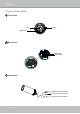
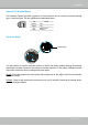
VIVOTEK Physical Description Front Panel Lens IR LED Light Sensor Back Panel Status LED Reset Button Connectors General I/O Terminal Block Ethernet 10/100 RJ45 Plug Power Cord Socket (black) 4 - User's Manual
VIVOTEK General I/O Terminal Block This Network Camera provides a general I/O terminal block which is used to connect external input / output devices. The pin definitions are described below.
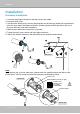
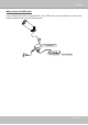
VIVOTEK Installation Hardware Installation 1. Loose the liquid tight connectors, and then remove the rubber. 2� Loose the back cover� 3� Tear down the aluminum foil vacuum bag and take out the silica gel� Attach the supplied silica gel to the inner side of the Network Camera� (Please replace the silica gel with a new one if you open the back cover after installation�) 4� Make sure all cable lines are securely connected� 5. Tighten the back cover, rubber and liquid tight connectors.
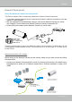
VIVOTEK Network Deployment Setup the Network Camera over the Internet This section explains how to configure the Network Camera to Internet connection� 1. If you have external devices such as sensors and alarms, make the connection from the general I/O terminal block� 2� Use the supplied RJ45 female/female coupler to connect the Network Camera to a switch.
VIVOTEK 2� In this case, if the Local Area Network (LAN) IP address of your Network Camera is 192�168�0�3, please forward the following ports for the Network Camera on the router� ■ HTTP port ■ RTSP port ■ RTP port for audio ■ RTCP port for audio ■ RTP port for video ■ RTCP port for video If you have changed the port numbers on the Network page, please open the ports accordingly on your router� For information on how to forward ports on the router, please refer to your router’s user’s manual� 3� Find out t
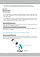
VIVOTEK When using a non-PoE switch If your switch/router does not support PoE, use a PoE power injector (optional) to connect the Network Camera and a non-PoE switch/router� PoE Power Injector (optional) POWER COLLISION 1 2 3 4 5 LINK RECEIVE PARTITION Non-PoE Switch User's Manual - 9
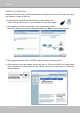
VIVOTEK Software Installation Installation Wizard 2 (IW2), free-bundled software included on the product CD, helps you set up your Network Camera on the LAN� 1� Install IW2 from the Software Utility directory on the software CD� Double click the IW2 shortcut on your desktop to launch the program� 2� The program will conduct an analysis of your network environment� After your network environment is analyzed, please click Next to continue the program� 3� The program will search for all VIVOTEK network devic
VIVOTEK Accessing the Network Camera This chapter explains how to access the Network Camera through web browsers, RTSP players, 3GPP-compatible mobile devices, and VIVOTEK recording software� Using Web Browsers Use Installation Wizard 2 (IW2) to access to the Network Cameras installed on the LAN. If your network environment is not a LAN, follow these steps to access the Network Camera: 1. Launch your web browser (ex. Microsoft® Internet Explorer, Mozilla Firefox, or Netscape). 2.
VIVOTEK ► By default, the Network Camera is not password-protected. To prevent unauthorized access, it is highly recommended to set a password for the Network Camera� For more information about how to enable password protection, please refer to Security on page 24� ► If you see a dialog box indicating that your security settings prohibit running ActiveX ® Controls, please enable the ActiveX ® Controls for your browser� 1� Choose Tools > Internet Options > Security > Custom Level� 2.
VIVOTEK Using RTSP Players To view the MPEG-4 streaming media using RTSP players, you can use one of the following applications that support RTSP streaming� Quick Time Player Real Player VLC media player 1� Launch a RTSP player� mpegable Player 2. Choose File > Open URL. A URL dialog box will pop up.
VIVOTEK Using 3GPP-compatible Mobile Devices To view the streaming media through 3GPP-compatible mobile devices, make sure the Network Camera can be accessed over the Internet� For more information on how to set up the Network Camera over the Internet, please refer to Setup the Network Camera over the Internet on page 7� To utilize this feature, please check the following settings on your Network Camera: 1� Because most players on 3GPP mobile phones do not support RTSP authentication, make sure the authent
VIVOTEK Using VIVOTEK Recording Software The product software CD also contains VIVOTEK’s recording software, allowing simultaneous monitoring and video recording for multiple Network Cameras� Please install the recording software, then launch the program to add the Network Camera to the Channel list� For detailed information about how to use the recording software, please refer to the user’s manual of the software or download the manual from http://www�vivotek�com� User's Manual - 15
VIVOTEK Main Page This chapter explains the layout of the main page. It is composed of the following sections: VIVOTEK INC� Logo, Host Name, Camera Control Area, Configuration Area, Menu, and Live Video Window� Logo of VIVOTEK INC. Host Name Camera Control Area Live View Window Configuration Area VIVOTEK INC. Logo Click this logo to visit the VIVOTEK website� Host Name The host name can be customized to fit your needs.
VIVOTEK Live Video Window ■ The following window is displayed when the video mode is set to MPEG-4: MPEG-4 Protocol and Media Options Video Title Title and Time Time Video 13:32:10 2008/12/22 Video Control Buttons Video Title: The video title can be configured. For more information, please refer to Video settings on page 43� MPEG-4 Protocol and Media Options: The transmission protocol and media options for MPEG-4 video streaming.
VIVOTEK Full Screen: Click this button to switch to full screen mode. Press the “Esc” key to switch back to normal mode� ■ The following window is displayed when the video mode is set to MJPEG: Video Title Title and Time Time Video 13:41:31 2008/12/22 Video Control Buttons Video Title: The video title can be configured.
VIVOTEK Client Settings This chapter explains how to select the stream transmission mode and saving options on the local computer.
VIVOTEK MP4 Saving Options Users can record live video as they are watching by clicking Here, you can specify the storage destination and file name. Start MP4 Recording on the main page� Folder: Specify the storage destination for the recorded video files. File name prefix: Enter the text that will be appended to the front of the video file name. Add date and time suffix to the file name: Select this option to append the date and time to the end of the file name.
VIVOTEK Configuration Click Configuration on the main page to enter the camera setting pages� Note that only Administrators can access the configuration page.
VIVOTEK Advanced Mode Configuration list Click to switch to Basic mode Firmware Version Each function on the configuration list will be explained in the following sections. Those functions that are displayed only in Advanced Mode are marked with Advanced Mode � If you want to set up the advanced functions, please click [Advanced Mode] on the bottom of the configuration list to quickly switch over.
VIVOTEK System Time Keep current date and time: Select this option to preserve the current date and time of the Network Camera� The Network Camera’s internal real-time clock maintains the date and time even when the system power is turned off� Sync with computer time: Select this option to synchronize the date and time of the Network Camera with the local computer� The read-only date and time of the PC is displayed when updated� Manual: The administrator can enter the date and time manually� Note that the
VIVOTEK Security This section explains how to enable password protection and create multiple accounts. Root Password The administrator account name is “root”, which is permanent and can not be deleted. If you want to add more accounts in the Manage User column, please set a password for the “root” account first. 1.
VIVOTEK HTTPS (Hypertext Transfer Protocol over SSL) Advanced Mode This section explains how to enable authentication and encrypted communication over SSL (Secure Socket Layer)� It helps protect streaming data transmission over the Internet on higher security level� Enable HTTPS Check this item to enable HTTPS communication, then select a connection option: "HTTP & HTTPS" or "HTTPS only".
VIVOTEK 4. The Certificate Information will automatically de displayed in the third column as shown below. You can click Property to view detailed information about the certificate. 5� Click Home to return to the main page� Change the address from “http://” to “https://“ in the address bar and press Enter on your keyboard� Some Security Alert dialogs will pop up� Click OK or Yes to enable HTTPS� https:// https://192.168.5.151/index.
VIVOTEK Create self-signed certificate manually 1� Select this option� 2� Click Create to open a Create Certificate page, then click Save to generate the certificate. 3. The Certificate Information will automatically be displayed in the third column as shown below. You can click Property to see detailed information about the certificate. Create certificate and install : Select this option if you want to create an official certificate issued by a CA (Certificate Authority).
VIVOTEK 3� If you see the following Information bar, click OK and click on the Information bar on the top of the page to allow pop-ups� 4. The pop-up window shows an example of a certificate request.
VIVOTEK 5. Look for a trusted certificate authority that issues digital certificates. Enroll the Network Camera. Wait for the certificate authority to issue a SSL certificate; click Browse...
VIVOTEK Network This section explains how to configure a wired network connection for the Network Camera.
VIVOTEK Network Camera (192.168.5.151) Enable UPnP port forwarding: To access the Network Camera from the Internet, select this option to allow the Network Camera to open ports on the router automatically so that video streams can be sent out from a LAN.
VIVOTEK ► Steps to enable UPnP TM user interface on your computer: Note that you must log on to the computer as a system administrator to install the UPnP TM components� 1� Go to Start, click Control Panel, and then click Add or Remove Programs� 2.
VIVOTEK 4. In the Networking Services dialog box, select Universal Plug and Play and click OK� 5� Click Next in the following window� 6� Click Finish� UPnP TM is enabled� ► How does UPnP TM work? UPnP TM networking technology provides automatic IP configuration and dynamic discovery of devices added to a network. Services and capabilities offered by networked devices, such as printing and file sharing, are available among each other without the need for cumbersome network configuration.
VIVOTEK HTTP Advanced Mode To utilize HTTP authentication, make sure that your have set a password for the Network Camera first; please refer to Security on page 26 for details� Authentication: Depending on your network security requirements, the Network Camera provides two types of security settings for an HTTP transaction: basic and digest� If basic authentication is selected, the password is sent in plain text format and there can be potential risks of being intercepted� If digest authentication is se
VIVOTEK URL command -- http://:/ For example, when the Access name for stream 2 is set to video2�mjpg: 1. Launch Mozilla Firefox or Netscape. 2� Type the URL command in the address bar� Press Enter� 3. The JPEG images will be displayed in your web browser. http://192.168.5.151/video2.
VIVOTEK RTSP Streaming To utilize RTSP streaming authentication, make sure that you have set a password for the Network Camera first; please refer to Security on page 24 for details� Authentication: Depending on your network security requirements, the Network Camera provides three types of security settings for streaming via RTSP protocol: disable, basic, and digest� If basic authentication is selected, the password is sent in plain text format, but there can be potential risks of it being intercepted� I
VIVOTEK RTSP port /RTP port for video, audio/ RTCP port for video, audio ■ RTSP (Real-Time Streaming Protocol) controls the delivery of streaming media. By default, the port number is set to 554� ■ The RTP (Real-time Transport Protocol) is used to deliver video and audio data to the clients.
VIVOTEK DDNS This section explains how to configure the dynamic domain name service for the Network Camera� DDNS is a service that allows your Network Camera, especially when assigned with a dynamic IP address, to have a fixed host and domain name. DDNS: Dynamic domain name service Enable DDNS: Select this option to enable the DDNS setting� Provider: Select a DDNS provider from the provider drop-down list� VIVOTEK offers Safe100.
VIVOTEK [Register] Successfully Your account information has been mailed to registered e-mail address 4� Select Enable DDNS and click Save to enable the setting� ■ CustomSafe100 VIVOTEK offers documents to establish a CustomSafe100 DDNS server for distributors and system integrators. You can use CustomSafe100 to register a dynamic domain name if your distributor or system integrators offer such services� 1� In the DDNS column, select CustomSafe100 from the drop-down list� 2.
VIVOTEK Access List Advanced Mode This section explains how to control access permission by verifying the client PC’s IP address.
VIVOTEK ■ Refresh: Click this button to refresh all current connections. ■ Add to deny list: You can select entries from the Connection Status list and add them to the Deny List to deny access� Please note that those checked connections will only be disconnected temporarily and will automatically try to re-link again (IE Explore or Quick Time Player). If you want to enable the denied list, please check Enable access list filtering and click Save in the first column.
VIVOTEK Range: This rule allows the user to assign a range of IP addresses to the Allow/Deny List� This rule is only applied to IPv4� For example: ■ Delete Allowed/Denied list: In the Delete Allowed List or Delete Denied List column, make a selection and click Delete� NOTE ► For example, when the range of IP addresses in the allowed list is set from 1.1.1.0 to 192.255.255.
VIVOTEK Video This section explains how to cofigure the audio and video settings of the Network Camera. Video Settings Video title: Enter a name that will be displayed on the title bar of the live video� Video title Color: Select to display color or black/white video streams� Power line frequency: Set the power line frequency consistent with local utility settings to eliminate image flickering associated with fluorescent lights.
VIVOTEK Overlay title and time stamp on video: Select this option to place the video title and time on the video streams� Note that when the frame size is set to 176 x 144 as shown in the picture below, only the time will be stamped on the video streams� 13:32:10 2008/12/22 Indoor Mode: To prevent color rolling effect under fluorescent light, please check this item to adjust the parameter� Image Settings Advanced Mode Click Image Settings to open the Image Settings page� On this page, you can tune White
VIVOTEK ■ Keep current value Follow the steps below to manually set the white balance to compensate for the ambient lighting conditions� 1� Set the White balance to Auto and click Save� 2� Place a sheet of white paper in front of the lens; then allow the Network Camera to adjust the color temperature automatically� 3. Select Keep current value to confirm the setting while the white balance is being measured.
VIVOTEK Video quality settings for stream 1 / stream 2 Advanced Mode The Network Camera offers two choices of video compression standards for real-time viewing: MPEG-4 and MJPEG. Click the items to display the detailed configuration settings. You can set up two seperate streams for the Network Camera for different viewing devices.
VIVOTEK ■ Intra frame period Determine how often to plant an I frame� The shorter the duration, the more likely you will get better video quality, but at the cost of higher network bandwidth consumption.
VIVOTEK IR LED With built-in IR illuminators, up to 15m, this Network Camera can make use of IR light during low light conditions� The IR LED supports five modes, Auto, Day, Night, Schedule and Disabled. ■ Auto mode The Network Camera automatically control the IR LED by judging the level of ambient light� ■ Day mode Select “Day mode” to turn on the IR LED. ■ Night mode Select “Night mode” to turn off the IR LED. ■ Schedule mode Select “Schedule mode” to control the IR LED by schedule.
VIVOTEK Motion Detection This section explains how to configure the Network Camera to enable motion detection. A total of three motion detection windows can be configured. Video(TCP-AV) Motion Detection Setting 1: for normal situation Motion Detection Setting 2: for special situation Follow the steps below to enable motion detection: 1� Click New to add a new motion detection window� 2. In the Window Name text box, enter a name for the motion detection window.
VIVOTEK A green bar indicates that even though motions have been detected, the event has not been triggered because the image variations still fall under the defined threshold. Percentage = 30% If you want to configure other motion detection settings for day/night/schedule mode, please click Profile to open the Motion Detection Profile Settings page as shown below� A total of three motion detection windows can be configured on this page as well.
VIVOTEK NOTE ► How does motion detection work? A C B D There are two motion detection parameters: Sensitivity and Percentage� In the illustration above, frame A and frame B are two sequential images. Pixel differences between the two frames are detected and highlighted in gray (frame C) and will be compared with the sensitivity setting� Sensitivity is a value that expresses the sensitivity to moving objects.
VIVOTEK Camera Tampering Detection This section explains how to set up camera temper detection.
VIVOTEK Homepage Layout Advanced Mode This section explains how to set up your own customized homepage layout. Preview This column shows the settings of your homepage layout. You can manually select the background and font colors in Theme Options, the third column on this page� The settings will automatically show up in this Preview field.
VIVOTEK Theme Options Here you can change the color of your homepage layout� There are three types of preset patterns for you to choose from� The new layout will simultaneously appear in the Preview filed.
VIVOTEK ■ Follow the steps below to set up the customed homepage: 1� Click Custom on the left column� 2. Click the field where you want to change the color on the right column. Color Selector Custom Pattern 3� The palette window will pop up as shown below� 2 3 1 4 4. Drag the slider bar and click on the left square to select a desired color. 5.
VIVOTEK Application Advanced Mode This section explains how to configure the Network Camera to react in response to particular situations (event)� A typical application is that when a motion is detected, the Network Camera sends buffered images to a FTP server or e-mail address as notifications. In the illustration on the right, an event can be triggered by many sources, such as motion detection or external digital input devices.
VIVOTEK Event Settings In the Event Settings column, click Add to open the Event Settings page� On this page, you can arrange three elements -- Trigger, Schedule, and Action to set an event� A total of 3 event settings can be configured. Event name: Enter a name for the event setting� Enable this event: Select this option to enable the event setting� Priority: Select the relative importance of this event (High, Normal, or Low)� Events with a higher priority setting will be executed first.
VIVOTEK An event is an action initiated by a user-defined trigger source; it is the causal arrangement of the following three elements: Trigger, Event Schedule, and Action� Trigger This is the cause or stimulus which defines when to trigger the Network Camera.
VIVOTEK ■ Camera tampering detection This option allows the Network Camera to trigger when the camera detects that is is being tampered with. To enable this function, you need to configure the Tampering Detection option first. Please refer to page 52 for detailed information� Event Schedule Specify the period for the event� ■ Select the days of the week. ■ Select the recording schedule in 24-hr time format. Action Define the actions to be performed by the Network Camera when a trigger is activated.
VIVOTEK To set an event with recorded video or snapshots, it is necessary to configure the server and media settings so that the Network Camera will know what action to take (such as which server to send the media files to) when a trigger is activated� ■ Add Server / Add Media Click Add Server to configure Server Settings� For more information, please refer to Server Settings on page 62� Click Add Media to configure Media Settings� For more information, please refer to Media Settings on page 65� Here is a
VIVOTEK When completed, click Save to enable the settings and click Close to exit Event Settings page.
VIVOTEK Server Settings Click Add Server on Event Settings page to open the Server Setting page� On this page, you can specify where the notification messages are sent when a trigger is activated. A total of 5 server settings can be configured. Server name: Enter a name for the server setting� Server Type There are four choices of server types available: Email, FTP, HTTP, and Network storage� Select the item to display the detailed configuration options. You can configure either one or all of them.
VIVOTEK FTP: Select to send the media files to an FTP server when a trigger is activated. ■ Server address: Enter the domain name or IP address of the FTP server. ■ Server port By default, the FTP server port is set to 21� It can also be assigned to another port number between 1025 and 65535� ■ User name: Enter the login name of the FTP account. ■ Password: Enter the password of the FTP account. ■ FTP folder name Enter the folder where the media file will be placed.
VIVOTEK HTTP: Select to send the media files to an HTTP server when a trigger is activated. ■ URL: Enter the URL of the HTTP server. ■ User name: Enter the user name if necessary. ■ Password: Enter the password if necessary. To verify if the HTTP settings are correctly configured, click Test� The result will be shown in a pop-up window as below. If successful, you will receive a test.txt file on the HTTP server. Click Save to enable the settings, then click Close to exit the page.
VIVOTEK Media Settings Click Add Media on the Event Settings page to open the Media Settings page� On this page, you can specify the type of media that will be sent when a trigger is activated� A total of 5 media settings can be configured. Media name: Enter a name for the media setting� Media Type There are three choices of media types available: Snapshot, Video clip, and System log� Select the item to display the detailed configuration options. You can configure either one or all of them.
VIVOTEK Video clip: Select to send video clips when a trigger is activated� ■ Source: Select to record video clips from stream 1 or stream 2. ■ Pre-event recording The Network Camera has a buffer area; it temporarily holds data up to a certain limit� Enter a number to decide the duration of recording before a trigger is activated� Up to 9 seconds can be set� ■ Maximum duration Specify the maximum recording duration in seconds. Up to 10 seconds can be set.
VIVOTEK Recording notify message: Select to send a recording notify message when a trigger is activated� Following is an example of recording notify message (.txt file), which shows a list of deleted recorded data due to cycle recording� When completed, click Save to take effect and then click Close to quit this page.
VIVOTEK Click 20081120 to open the directory: The format is: HH (24r) Click to open the file list of that hour Click to delete selected items Click to go back to the previous level of the directory Click to delete all recorded data The format is: File name prefix + Minute (mm) You can set up the File name prefix on Media Settings page.
VIVOTEK Recording Advanced Mode This section explains how to configure the recording settings for the Network Camera. Recording Settings NOTE ► Before setting up this page, please set up the Network Storage on the Server Settings page first.
VIVOTEK If successful, you will receive a test.txt file on the network storage server. 3� Enter a server name� 4� Click Save to complete the settings and click Close to exit the page. Recording Settings Click Add to open the recording setting page� On this page, you can define the recording source, recording schedule and recording capacity. A total of 2 recording settings can be configured.
VIVOTEK Source: Select the recording source (stream 1 or stream 2)� Recording Schedule: Specify the recording duration� ■ Select the days of the week. ■ Select the recording start and end times in 24-hr time format. Destination: You can select the network storage to store the recorded video files. Capacity: You can choose either the “entire free space available” or “limit the recording size”. The recording size limit must be larger than the reserved amount for cyclic recording.
VIVOTEK System Log Advanced Mode This section explains how to configure the Network Camera to send the system log to the remote server as backup� Remote Log You can configure the Network Camera to send the system log file to a remote server as a log backup. Before utilizing this feature, it is suggested that the user install a log-recording tool to receive system log messages from the Network Camera. An example is Kiwi Syslog Daemon.
VIVOTEK View Parameters Advanced Mode The View Parameters page lists the entire system’s parameters in alphabetical order� If you need technical assistance, please provide the information listed on this page� User's Manual - 73
VIVOTEK Maintenance This chapter explains how to restore the Network Camera to factory default, upgrade firmware version, etc� Reboot This feature allows you to reboot the Network Camera, which takes about one minute to complete� When completed, the live video page will be displayed in your browser� The following message will be displayed during the rebooting process� If the connection fails after rebooting, manually enter the IP address of the Network Camera in the address field to resume the connection
VIVOTEK Export / Upload Files Advanced Mode This feature allows you to Export / Upload daylight saving time rules, custom language files, and setting backup files. Export daylight saving time configuration file: Click to set the start and end time of DST� Follow the steps below to export: 1. In the Export files column, click Export to export the daylight saving time configuration file from the Network Camera� 2. A file download dialog will pop up as shown below.
VIVOTEK Upload daylight saving time rule: Click Browse… and specify the XML file to upload. If the incorrect date and time are assigned, you will see the following warning message when uploading the file to the Network Camera. The following message is displayed when attempting to upload an incorrect file format. Export language file: Click to export language strings.
VIVOTEK The following message is displayed when the upgrade has succeeded� Reboot system now!! This connection will close. The following message is displayed when you have selected an incorrect firmware file. Starting firmware upgrade... Do not power down the server during the upgrade. The server will restart automatically after the upgrade is completed. It will takes about 1 - 5 minutes.
VIVOTEK Appendix URL Commands for the Network Camera Overview For some customers who already have their own web site or web control application, the Network Camera/Video Server can be easily integrated through URL syntax. This section specifies the external HTTP-based application programming interface� The HTTP-based camera interface provides the functionality to request a single image, control camera functions (PTZ, output relay etc.), and get and set internal parameter values.
VIVOTEK General CGI URL syntax and parameters CGI parameters are written in lower-case and as one word without any underscores or other separators. When the CGI request includes internal camera parameters, the internal parameters must be written exactly as they are named in the camera or video server. The CGIs are organized in function related directories under the cgi-bin directory. The file extension of the CGI is required. Syntax: http:///cgi-bin/[/...]/.
VIVOTEK http:///cgi-bin/viewer/getparam.cgi?[] [&…] http:///cgi-bin/operator/getparam.cgi?[] [&…] http:///cgi-bin/admin/getparam.cgi?[] [&…] where the should be [_] or [.] If you do not specify the any parameters, all the parameters on the server will be returned. If you specify only , the parameters of related group will be returned.
VIVOTEK Set server parameter values Note: The access right depends on the URL directory. Method: GET/POST Syntax: http:///cgi-bin/anonymous/setparam.cgi? = [&=…][&update=][&return=] http:///cgi-bin/viewer/setparam.cgi? = [&=…][&update=] [&return=] http:///cgi-bin/operator/setparam.
VIVOTEK where is =\r\n [] Only the parameters that you set and readable will be returned. Example: Set the IP address of server to 192.168.0.123 Request: http://myserver/cgi-bin/admin/setparam.cgi?network_ipaddress=192.168.0.123 Response: HTTP/1.0 200 OK\r\n Content-Type: text/html\r\n Context-Length: 33\r\n \r\n network.ipaddress=192.168.0.
VIVOTEK Group: system NAME VALUE SECURITY DESCRIPTION (get/set) hostname string[40] 1/6 host name of server (Network Camera, Wireless Network Camera, Video Server, Wireless Video Server) lowlight 6/6 (0) Turn on white light LED in all condition (1) Only turn on white light LED in low light condition (product dependent) date time , 6/6 Current date of system. Set to ‘keep’ keep, keeping date unchanged. Set to ‘auto’ to auto use NTP to synchronize date.
VIVOTEK -160: GMT-04:00 Atlantic Time, Canada, La Paz, Santiago -140: GMT-03:30 Newfoundland -120: GMT-03:00 Brasilia, Buenos Aires, Georgetown, Greenland -80: GMT-02:00 Mid-Atlantic -40: GMT-01:00 Azores, Cape_Verde_IS.
VIVOTEK 380: GMT 09:30 Adelaide, Darwin 400: GMT 10:00 Brisbane, Canberra, Melbourne, Sydney, Guam, Vladivostok 440: GMT 11:00 Magadan, Solomon Is., New Caledonia 480: GMT 12:00 Aucklan, Wellington, Fiji, Kamchatka, Marshall Is. 520: GMT 13:00 Nuku'Alofa daylight_enable 6/6 enable automatic daylight saving to time zone daylight_dstactual 6/7 mode daylight_auto_begi check if current time is under daylight saving time.
VIVOTEK This command can cooperate with other “restoreexceptXYZ” commands. When cooperating with others, the system parameters will be restored to default value except a union of combined results. restoreexceptlang 7/6 Restore the system parameters to default value except custom language file user uploaded. This command can cooperate with other “restoreexceptXYZ” commands.
VIVOTEK 1 => Active, triggered daynight day, 7/7 The day/night status judge by light sensor night onlinenum_rtsp integer 6/7 current RTSP connection numbers onlinenum_httppush integer 6/7 current HTTP push server connection numbers Group: di_i<0~(ndi-1)> (capability.ndi > 0) NAME VALUE SECURITY DESCRIPTION (get/set) normalstate high, 1/1 indicate whether open circuit or closed circuit low represents inactive status Group: do_i<0~(ndo-1)> (capability.
VIVOTEK DHCP server at next reboot 0 => use preset ipaddress, subnet, rounter, dns1, and dns2 ipaddress 6/6 IP address of server subnet 6/6 subnet mask router 6/6 default gateway dns1 6/6 primary DNS server dns2 6/6 secondary DNS server wins1 6/6 primary WINS server wins2 6/6 secondary WINS server Subgroup of network: ftp NAME VALUE SECURITY DESCRIPTION (get/set) port 21, 1025~65535
VIVOTEK NAME VALUE SECURITY DESCRIPTION (get/set) port 554, 1025 ~ 65535 1/6 RTSP port (capability.protocol.rtsp=1) anonymousviewing 1/6 Enable anoymous streaming viewing. authmode disable, 1/6 RTSP authentication mode basic, (capability.protocol.rtsp=1) digest s0_accessname string[3b;42] 1/6 RTSP access name for stream1 (capability.protocol.rtsp=1 and video.stream.count>0) s1_accessname string[32] 1/6 RTSP access name for stream2 (capability.protocol.rtsp=1 and video.
VIVOTEK pass password[64] 6/6 PPPoE account password SECURITY DESCRIPTION Group: ipfilter NAME VALUE (get/set) enable 6/6 Enable or disable ipfilter settings admin_enable 6/6 Enable or disable the function always allow the admin IP address to access this device admin_ip 1.0.0.0 ~ 6/6 Always allow this IP connect to camera when 255.255.255.255 maxconnection 0~10 admin_enable=1 6/6 Maximum number of concurrent streaming connection(s) limit allow_i<0~9>_start 1.0.
VIVOTEK 1 => color flip 4/4 flip the image mirror 4/4 mirror the image text string[16] 1/4 enclosed caption imprinttimestamp 4/4 Overlay time stamp on video maxexposure 1~30 4/4 Maximum exposure time scenemode 0, 1 4/4 0 => outdoor mode 1 => indoor mode s<0~(m-1)>_codectype mpeg4, mjpeg 4/4 video codec type s<0~(m-1)>_resolution VGA CMOS => 4/4 Video resolution in pixel 4/4 The period of intra frame in 176x144, 320x240, 640x480 s<0~(m-1)>_mpeg
VIVOTEK encoder. 10 is best quality and 200 is the worst quality. s<0~(m-1)>_mjpeg_maxfra 1~25, 4/4 me 26~30 (only for set maximum frame rate in fps (for JPEG) 60Hz CMOS) s<0~(m-1)>_forcei 1 7/6 Force I frame Group: image_c<0~(n-1)> for n channel products NAME VALUE SECURITY DESCRIPTION (get/set) brightness -5 ~ 5 4/4 Adjust brightness of image according to mode settings. saturation -5 ~ 5 4/4 Adjust saturation of image according to mode settings.
VIVOTEK win_i <0~2>_top 0 ~ 240 4/4 Top coordinate of window position. win_i <0~2>_width 0 ~ 320 4/4 Width of motion detection window. win_i<0~2>_height 0 ~ 240 4/4 Height of motion detection window. win_i<0~2>_objsize 0 ~ 100 4/4 Percent of motion detection window. win_i<0~2>_sensitivity 0 ~ 100 4/4 Sensitivity of motion detection window.
VIVOTEK Group: ddns NAME VALUE SECURITY DESCRIPTION (get/set) enable 6/6 Enable or disable the dynamic dns. provider Safe100, 6/6 Safe100 => safe100.net DyndnsDynamic, DyndnsDynamic => dyndns.org (dynamic) DyndnsCustom, DyndnsCustom => dyndns.org (custom) TZO, TZO => tzo.com DHS, DHS => dhs.org DynInterfree, DynInterfree =>dyn-interfree.it CustomSafe100 CustomSafe100 => Custom server using safe100 method _hostn string[128] 6/6 Your dynamic hostname.
VIVOTEK (get/set) enableremotelog 6/6 enable remote log serverip 6/6 Log server IP address serverport 514, 1025~65535 6/6 Server port used for log level 0~7 6/6 The levels to distinguish the importance of information.
VIVOTEK enable 4/4 Enable the privacy mask win_i<0~4>_enable 4/4 Enable the privacy mask window win_i<0~4>_name string[14] 4/4 The name of privacy mask window win_i<0~4>_left 0 ~ 320/352 4/4 Left coordinate of window position. win_i<0~4>_top 0 ~ 240/288 4/4 Top coordinate of window position.
VIVOTEK ptzenabled < positive integer > 0/7 An 32-bits integer, each bit can be set separately as follows: Bit 0 => Support camera control function 0(not support), 1(support) Bit 1 => Build-in or external camera. 0(external), 1(build-in) Bit 2 => Support pan operation. 0(not support), 1(support) Bit 3 => Support tilt operation. 0(not support), 1(support) Bit 4 => Support zoom operation. 0(not support), 1(support) Bit 5 => Support focus operation.
VIVOTEK protocol_rtp_multica 0/7 st_scalable protocol_rtp_multica indicate whether to support scalable multicast 0/7 st_backchannel indicate whether to support backchannel multicast protocol_rtp_tcp 0/7 indicate whether to support rtp over tcp protocol_rtp_http 0/7 indicate whether to support rtp over http protocol_spush_mjpe 0/7 indicate whether to support server push g motion jpeg protocol_snmp 0/7 indicate whether to s
VIVOTEK for event/control transfer joystick 0/7 Indicate whether to support the joystick control Group: event_i<0~2> PARAMETER VALUE SECURITY DESCRIPTION (get/set) name string[40] 6/6 The identification of this entry enable 0, 1 6/6 To enable or disable this event. priority 0, 1, 2 6/6 Indicate the priority of this event. “0” indicates low priority. “1” indicates normal priority. “2” indicates high priority. delay 1~999 6/6 Delay seconds before detect next event.
VIVOTEK mdwin0 6/6 Indicate which motion detection windows of motion profile 0 detected. This field is required when trigger condition is “md”. One bit represents one window. The LSB indicates the 1st window. For example, to detect the 1st and 3rd windows, set mdwin as 5. inter 1~999 6/6 Interval of period snapshot in minute. This field is used when trigger condition is “seq”. weekday 6/6 Indicate which weekday is scheduled. One bit represents one weekday.
VIVOTEK PARAMETER VALUE SECURITY DESCRIPTION (get/set) name string[40] 6/6 The identification of this entry type email, 6/6 Indicate the server type. ftp, “email” is email server. http, “ftp” is ftp server. ns “http” is http server. “ns” is network storage. http_url string[128] 6/6 The url of http server to upload. http_username string[64] 6/6 The username to login in the server. http_passwd string[64] 6/6 The password of the user.
VIVOTEK Group: media_i<0~4>(media_freespace is used internally.) PARAMETER VALUE SECURITY DESCRIPTION (get/set) name string[40] 6/6 The identification of this entry type snapshot, The media type to send to the server or store by the server. 6/6 systemlog videoclip snapshot_source 6/6 Indicate the source of media stream. 0 means the first stream. 1 means the second stream and etc. snapshot_prefix string[16] 6/6 Indicate the prefix of the filename.
VIVOTEK source 6/6 Indicate the source of media stream. 0 means the first stream. 1 means the second stream and etc. weekday 6/6 Indicate which weekday is scheduled. One bit represents one weekday. The bit0 (LSB) indicates Saturday. The bit1 indicates Friday. The bit2 indicates Thursday. The bit3 indicates Wednesday. The bit4 indicates Tuesday. The bit5 indicates Monday. The bit6 indicates Sunday. For example, to detect events on Friday and Sunday, set weekday as 66.
VIVOTEK reserveamount 15~ 6/6 The reserve amount in Mbytes when choose cyclic recording mechanism. dest cf, 6/6 The destination to store the recording data. 0~4 “cf” means CF card. “0~4” means the index of network storage. cffolder string[128] 6/6 folder name. Group: custom_i<0~2> PARAMETER VALUE SECURITY DESCRIPTION (get/set) name string[40] 6/6 The identification of customize event script file.
VIVOTEK localityname string[128] 6/6 the locality name in certificate information organizationna string[64] 6/6 organization naem in certificate information unit string[32] 6/6 organizational unit name in certificate information commonname string[64] 6/6 common name in certificate information validdays 0 ~ 9999 6/6 certificatation valid period me Query status of the digital input Note: This request requires the privilege of viewer.
VIVOTEK Capture single snapshot Note: This request require normal user privilege Method: GET/POST Syntax: http:///cgi-bin/viewer/video.
VIVOTEK PARAMETER VALUE DESCRIPTION method Add Add an account to server. When using this method, “username” field is necessary. It will use default value of other fields if not specified. Delete Remove an account from server. When using this method, “username” field is necessary, and others are ignored. edit Modify the account password and privilege. When using this method, “username” field is necessary, and other fields are optional. If not specified, it will keep original settings.
VIVOTEK \r\n \r\n Upgrade firmware Note: This request requires administrator privilege Method: POST Syntax: http:///cgi-bin/admin/upgrade.cgi Post data: fimage=[&return=]\r\n \r\n Server will accept the upload file named to be upgraded the firmware and return with if indicated.
VIVOTEK CapVersion=0200\r\n PARAMETER(supported VALUE DESCRIPTION system.firmwareversion Model name of server. capability version) Model Ex:IP3133-VVTK-0100a CapVersion MMmm, MM is major version from 00 ~ 99 The capability field version mm is minor version from 00 ~ 99 ex: 0100 IP filtering Note: This request requires administrator access privilege Method: GET/POST Syntax: http:///cgi-bin/admin/ipfilter.
VIVOTEK deletedeny Remove a set of deny IP address range from server. If start and end parameters are specified, it will try to remove the matched IP address. If index is specified, it will try to remove the address from given index position. [start, end] parameters have higher priority then the [index] parameter. start The start IP address to add or to delete. end The end IP address to add or to delete. index The start position to add or to delete.
VIVOTEK upstream should be base64 encoded to be able to pass through some proxy server. This channel will help to do real-time event notification and control. The event and control format are described in another document. Get SDP of Streamings Note: This request requires viewer access privilege Method: GET/POST Syntax: http:///_accessname> “m” is the stream number. “network_accessname_<0~(m-1)>” is the accessname for stream “1” to stream “m”.
VIVOTEK Ver� 0�2 Technical Specifications Specifications System .CPU: VVTK-1000 SoC .Flash: 8 MB .RAM: 32 MB .Embedded OS: Linux 2.4 Lens .Board lens, dual-band, f= 4.0 mm, F1.8, Fixed .IR corrected Angle of View .56° (horizontal) .42° (vertical) .71° (diagonal) Shutter Time .1/5 sec. to 1/15000 sec. Image Sensor .1/4” CMOS sensor in VGA resolution Minimum Illumination .0 Lux / F1.
VIVOTEK Technology License Notice MPEG-4 AAC Technology THIS PRODUCT IS LICENSED UNDER THE MPEG-4 AAC AUDIO PATENT LICENSE. THIS PRODUCT MAY NOT BE DECOMPILED, REVERSE-ENGINEERED OR COPIED, EXCEPT REGARD TO PC SOFTWARE, YOU MAY MAKE SINGLE COPIES FOR ARCHIVAL PURPOSES.
VIVOTEK Electromagnetic Compatibility (EMC) FCC Statement This device compiles with FCC Rules Part 15� Operation is subject to the following two conditions� ■ This device may not cause harmful interference, and ■ This device must accept any interference received, including interference that may cause undesired operation� This equipment has been tested and found to comply with the limits for a Class A digital device, pursuant to Part 15 of the FCC Rules� These limits are designed to provide reasonable prote