Product name: Wireless Network Camera with Pan/Tilt(TC5632/TC5633) Release Date: 2008/01/04 Manual Revision: 1.00 Web site: www.vivotek.com Email: technical@vivotek.com sales@vivotek.com © 2008 VIVOTEK INC. All rights reserved -1www.vivotek.
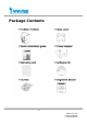
Before You Use This Product The use of surveillance devices may be prohibited by law in your country. The Network Camera is not only a high-performance web-ready camera but also can be part of a flexible surveillance system. It is the user’s responsibility to ensure that the operation of such devices is legal before installing this unit for its intended use. It is important to first verify that all contents received are complete according to the list in the "Package Contents" chapter.
Table of Contents Before You Use This Product......................................................................2 Package Contents ....................................................................................5 Installation .............................................................................................6 Hardware installation..........................................................................6 Software Installation .................................................................
Video Settings............................................................................ 41 Video orientation ........................................................................ 41 Image Settings .......................................................................... 41 Audio settings ............................................................................ 44 Camera Control ............................................................................... 46 Motion detection .....................
Package Contents -5www.vivotek.
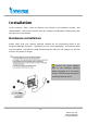
Installation In this manual, "User" refers to whoever has access to the Network Camera, and "Administrator" refers to the person who can configure the Network Camera and grant user access to the camera. Hardware installation Please verify that your product package contains all the accessories listed in the foregoing Package Contents. Depending on the user’s application, an Ethernet cable may be needed. The Ethernet cable should meet the specs of UTP Category 5 and not exceed 100 meters in length.
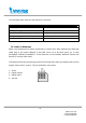
The following table lists the LED patterns in general: Condition LED color Loading system after power on Steady red During booting procedure Steady blue and red After network is setup (system up) Blink green every second During the upgrade firmware process Fast blink red Enable audio Slowly blink green To install in Ethernet Make sure the Ethernet is firmly connected to a switch hub. After attaching the Ethernet cable plug in the power adapter.
Software Installation At the end of the hardware installation, users can use “Installation Wizard 2” program included in the product CDROM to find the location of the Network Camera. There may be many Network Cameras in the local network. Users can differentiate the Network Cameras with the serial number. The serial number is printed on the labels on the carton and the back of the Network Camera body. Please refer to the user’s manual of Installation Wizard 2 for details.
before each access. The Administrator can set up a maximum of twenty (20) user accounts. Each user can access the Network Camera except to perform system configuration. Some critical functions are exclusive for the Administrator, such as system configuration, user administration, and software upgrades. The user name for the Administrator is permanently assigned as “root”. Once the password is changed, the browser will display an authentication window to ask for the new password.
*If the administrator (root user) assigns no password, everybody can access the homepage directly. Installing plug-in For the initial access to the Network Camera in Windows, the web browser may prompt for permission to install a new plug-in for the Network Camera. Permission request depends on the Internet security settings of the user’s PC or notebook. If the highest security level is set, the computer may prohibit any installation and execution attempt.
- 11 www.vivotek.
Primary user’s capability Main Screen with Camera View The main page layout has three parts: Configuration functions: The camera can be configured using these user interfaces. Camera View: What the camera sees. Pan/Tilt control buttons: These buttons provide a command interface to control the aim of the camera. Click on the configuration link to the left of the image window to enter the configuration page.
Clicking on this button links you to the client setting pages, please check the following session for more details. “Configuration” Only the Administrator can access camera configurations. The camera view: The information bar at the top of the camera view shows the connection type to the Network Camera and the current date/time. The camera view provides not only the live video, but also a way to aim the Network Camera to different target.
Mute Digital Zoom Play volume Record Stop Play/Pause “Play” The option will connect to the Network Camera. The button is the same one as “Pause”. “Pause” The option will pause the video, but the connection remains. The button is the same one as “Play”. “Stop” The option will disconnect to the Network Camera. “Play volume” Click on this button can adjust the audio volume. - 14 www.vivotek.
“Mute” Disable audio at client side. “Record” This option will tart MP4 recording. The pan/tilt control buttons: The direction buttons are for Left, Right, Up, Down, and Home functions. The Home button centers the camera. “Go to” Once the Administrator has determined the preset positions; the User can aim the camera using this control. “Pan speed” This button sets the moving range of the “Left” and “Right” commands. “Tilt speed” This button sets the moving range of the “Up” and “Down” commands.
- 16 www.vivotek.
Client settings At the initial access to the “Connection type” page in Windows, the web browser will ask for a new plug-in installation, the plug-in being the Network Camera. This plug-in has been registered for certification and can be used to change the parameters at the client’s site. The user may click on to install the plug-in. If the web browser does not allow the user to complete the installation, check the Internet security to lower the security level or contact your IT or networking supervisor.
The UDP protocol allows for more real-time audio and video streams. However, some packets may be lost due to network burst traffic and images may be obscured. The TCP protocol allows for less packet loss and produces a more accurate video display. The downside with this protocol is that the real-time effect is worse than that with the UDP protocol. The HTTP protocol allows the media can be streaming through http port when the UDP or TCP protocol are blocked.
http:///client.html is the domain name or the original IP address of the Network Camera. - 19 www.vivotek.
Administrator’s capability Fine-tuning for Best Performance Best performance generally equates to the fastest image refresh rate with the best video quality, and at the lowest network bandwidth as possible. The three factors, “Maximum frame rate”, “Constant bit rate”, and “Fix quality” on the Audio and Video Configuration page, are correlative to allow for achieving the best performance possible. - 20 www.vivotek.
For Viewing by Mobile Phone Most 3GPP cell phone supports media streaming with MPEG4 video and GSM-AMR audio. Due to the limitation of the bandwidth for 3GPP, only 176x144 size video is supported for cell phone viewing. Select the “Configure for mobile viewing” option will change the range of other related video settings. For Best Real-time Video Images To achieve good real-time visual effect, the network bandwidth should be large - 21 www.vivotek.
enough to allow a transmission rate of greater than 20 image frames per second. If the broadband network is over 1 Mbps, set the “Fix bit rate” to 1000Kbps or 1200Kbps. The maximum frame rate is 30. If your network bandwidth is more than 512Kbps, you can fix the bit rate according to your bandwidth and set the maximum frame rate to 30 fps. If the images vary dramatically in your environment, you may want to slow the maximum frame rate down to 20 fps in order to lower the rate of data transmission.
Opening accounts for new users 1 2 3 Protect Network Camera by passwords The Network Camera is shipped without any password by default. That means everyone can access the Network Camera including the configuration as long as the IP address is known. It is necessary to assign a password if the Network Camera is 1 to enable protection. intended to be accessed by others. Type a new word twice in ○ This password is used to identify the administrator. Then add an account with user 2 .
Build a security application The Administrator can use the built-in motion detection to monitor any movement to perform many useful security applications. To upload the snapshots, users can choose either email or FTP according to user’s needs. Both e-mail and FTP use the network settings on the Email and FTP page. Refer to the definition section for detail configuration. 1. Click on “Configuration” on homepage, 2. Click on “Motion detection” at the left column, 3. Check “Enable motion detection”, 4.
Click on save to validate. Software revision upgrade Customers can obtain the up-to-date software from the web site of Vivotek. An easy-to-use Upgrade Wizard is provided to upgrade the Network Camera with just a few clicks. The upgrade function is opened to the Administrator only. To upgrade the system, follow the procedures below. 1. Download the firmware file named “xxx.pkg” from the appropriate product folder. 2. Run the Upgrade Wizard and proceed following the prompts.
Definitions in Configuration Only the Administrator can access system configuration. Each category in the left column will be explained in the following pages. The bold texts are the specific phrases on the Option pages. The Administrator may type the URL below the figure to directly enter the frame page of configuration. If the Administrator also wants to set certain options through the URL, read the reference appendix for details. http:///setup/config.
Camera. http:///setup/system.html is the domain name or original IP address of the Network Camera. - 27 www.vivotek.
System parameters "Host name" The text displays the title at the top of the main page. “Turn off the LED indicator” Check this option to shut off the LED on the rear. It can prevent the camera’s operation being noticed. “Enable Daylight Saving Time” Check this option to enable daylight saving time. "Time zone" Adjust the time with that of the time-servers for local settings. "Keep current date and time" Click on this to reserve the current date and time of the Network Camera.
Security settings “Root password” Change the Administrator’s password by typing in the new password identically in both text boxes. The typed entries will be displayed as asterisks for security purposes. After pressing , the web browser will ask the Administrator for the new password for access. “Add user” Type the new user's name and password and press to insert the new entry. The new user will be displayed in the user name list. There is a maximum of twenty user accounts.
http:///setup/security.html is the domain name or original IP address of the Network Camera. - 30 www.vivotek.
Network settings Any changes made on this page will restart the system in order to validate the changes. Make sure every field is entered correctly before clicking on . Network type “LAN” & “PPPoE” The default type is LAN. Select PPPoE if using ADSL "Get IP address automatically" & “Use fixed IP address” The default status is “Get IP address automatically”. This can be tedious having to perform software installation whenever the Network Camera starts.
“Password” The password of PPPoE account “Confirm password” Input password again for confirmation HTTP “Http port” This can be other than the default Port 80. Once the port is changed, the users must be notified the change for the connection to be successful. For instance, when the Administrator changes the HTTP port of the Network Camera whose IP address is 192.168.0.100 from 80 to 8080, the users must type in the web browser “http://192.168.0.100:8080” instead of “http://192.168.0.100”.
“Multicast rtcp audio port” This port must be multicast audio port plus 1. “Multicast TTL” This option indicates the Time-To-Live of multicast packets. - 33 www.vivotek.
http:///setup/network.html is the domain name or original IP address of the Network Camera. - 34 www.vivotek.
WLAN Configuration (TC5633 only) “SSID” (Service Set Identifier), it is a name that identifies a wireless network. Access Points and wireless clients attempting to connect to a specific WLAN (Wireless Local Area Network) must use the same SSID. The default setting is default. Note: The maximum length of SSID is 32 single-byte characters and SSID can’t be any of “, <, > and space character.
64bits is the default setting. “Key format” Hexadecimal or ASCII. “HEX” is the default setting. ▶ “HEX” digits consist of the numbers 0~9 and the letters A-F. ▶ “ASCII” is a code for representing English letters as numbers from 0-127 except “, <, > and space characters that are reserved. “Network Key” Entering a key in either hexadecimal or ASCII format. When selecting different key length, acceptable input length is listed as following: 64 bits key length: 10 Hex digits or 5 characters.
http:///setup/wireless.html is the domain name or original IP address of the Network Camera. - 37 www.vivotek.
DDNS “Enable DDNS” This option turns on the DDNS function. “Provider” The provider list contains four hosts that provide DDNS services. Please connect to the service provider’s website to make sure the service charges. “Host Name” If the User wants to use DDNS service, this field must be filled. Please input the hostname that is registered in the DDNS server. “Username/E-mail” The Username or E-mail field is necessary for logging in the DDNS server or notify the User of the new IP address.
is the domain name or original IP address of the Network Camera. Access List The access list is to control the access permission of clients by checking the client IP address. There are two lists for permission control: Allow List and Deny List. Only those clients whose IP address is in the Allow List and not in the Deny List can connect to the Video Server or Network Camera for receiving the audio/video streaming. Both Allow List and Deny List consist of a list of IP ranges.
http:///setup/accesslist.html is the domain name or original IP address of the Network Camera. - 40 www.vivotek.
Audio and Video Video Settings “Video title” The text string can be displayed on video “Color” Select either for color or monochrome video display. “Power line frequency (for fluorescent light)”, the fluorescent light will flash according to the power line frequency that depends on local utility. Change the frequency setting to eliminate uncomfortable flash image when the light source is only fluorescent light. Video orientation “Flip” Vertically rotate the video. “Mirror” Horizontally rotate the video.
Brightness Adjust the image brightness in 11 steps from +5 ~ -5. The default value is set to 0. Contrast Adjust the image contrast in 11 steps from +5 ~ -5. The default value is set to 0. Saturation Adjust the image color saturation in 7 steps from +1 ~ -5. The default value is set to 0. Sharpness - 42 www.vivotek.
Adjust the image sharpness in 7 steps from +3 ~ -3. The default value is set to + 3. White balance ● Auto The camera automatically adjusts the color temperature of light in response to different light sources. The white balance setting defaults to Auto and works well in most situations. ● Keep current value Manually set the white balance to compensate for the ambient lighting conditions. Step1: Set the White balance to Auto.
“Mode” It can be MPEG-4 or JPEG. If MPEG-4 is selected, it is streamed in RTSP protocol. If JPEG is selected, it is streamed in server push mode. “Frame Size” Both MPEG-4 and JPEG video mode have three options to choose: “176x144”, “320x240” and “640x480”. There are three dependent parameters provided for video performance adjustment.
http:///setup/audiovideo.html is the domain name or original IP address of the Network Camera. - 45 www.vivotek.
Camera Control Camera control area Preset function area On the Camera Control page, there are two main function control areas: Camera control area The pan and tilt functions can be controlled with these buttons. The “Left” button aims the camera to the left; the “Right”, “Up”, and “Down” buttons aim the camera accordingly. The “Home” button aims the camera to the center. “Pan speed” This controls the range of the horizontal movement of the camera.
greater the value, the greater angular movement when performing the “Up” or “Down” functions would be. “Auto pan/patrol speed” This defines the speed of panning and patrol, the greater the value, the faster the speed. Preset function area ”Current position”, If the User wants to save the current view as a preset location, enter a name for each of the current video view at “current position” and click on the “Add” button. The camera allows for 20 preset locations.
Motion detection “Enable motion detection” Check this option to turn on motion detection. Click on this button to add a new window. At most three windows can exist simultaneously. Use the mouse to click, hold, and drag the window frame to resize or the title bar to move. Clicking on the ‘x’ at the upper right-hand corner of the window to delete the window. Remember to save in order to validate the changes. Click on this button to save the related window settings.
- 49 www.vivotek.
Application There are three sections in application page. They are event, server and media. Click to pop a window to add a new item of event, server or media. Click to delete the selected item from event, server or media. Click on the item name to pop a window to edit it. There can be at most three events. There can be at most five server and five media configurations. User can know the event name, status, weekly and time schedule and trigger type in event section.
http:///setup/application.htm is the domain name or original IP address of the Network Camera. Event “Event name” The unique name for event “Enable this event” Check it to enable this event. “Priority” The event with higher priority will be executed first. “Delay second(s) before detecting next event” The delay to check next event. It is used in motion detection and digital input trigger type. There are four kinds of trigger supported.
“Digital input” To monitor digital input “System boot” The event is triggered when the system bootup. The weekly and time schedules are provided. “Sun” ~ “Sat” Select the days of the week to perform the event. “Time” show “Always” or input the time interval. “Trigger DO” Check it to trigger digital output for specific seconds when event is triggered. “Server name” Check it to sending the selected media when event is triggered. Server “Server name” The unique name for server - 52 www.vivotek.
There are four kinds of servers supported. They are email server, FTP server and HTTP server. Here is setting for email server. “Sender email address” The email address of the sender “Recipient email address” The email address of the recipient “Server address” The domain name or IP address of the external email server. “User name” This granted user name on the external email server. “Password” This granted password on the external email server. Here is setting for FTP server.
Media “Media name” The unique name for media There are three kinds of media. They are snapshot, video clip and system log. Here is setting for snapshot. “Source” The source of stream, stream1 or stream2. “Send Pre-event images” The number of pre-event images “Send Post-event images” The number of post-event images “File name prefix” The prefix name will be added on the file name of the snapshot images. “Add date and time suffix to file name” Check it to add timing information as file - 54 www.vivotek.
name suffix. Here is setting for video clip “Source” The source of stream, stream1 or stream2. “Pre-event recording” The interval of pre-event recording in seconds There are two limitations for video clip file. “Maximum duration” The maximal recording file duration in seconds “Maximum file size” The maximal file size would be generated. “File name prefix” The prefix name will be added on the file name of the video clip. - 55 www.vivotek.
System log The Network camera support log the system messages on remote server. The protocol is compliant to RFC 3164. If you have external Linux server with syslogd service, use “-r” option to turn on the facility for receiving log from remote machine. Or you can use some software on Windows which is compliant to RFC 3164. Check “Enable remote log” and input the “IP address” and “port” number of the log server to enable the remote log facility. In the “Current log”, it displays the current system log file.
Viewing system parameters Click on this link on the configuration page to view the entire system’s parameter set. The content is the same as those in CONFIG.INI. - 57 www.vivotek.
- 58 www.vivotek.
Maintenance Six actions can be selected. “Reboot system” Click the reboot button to restart system “Restore” Click it to restore all setting to factory default except setting in “Network type” in network page and/or Daylight Saving Time in system page. “Upload” Click to upload daylight saving time rules to the camera server. “Export Daylight Saving Time Configuration File” If you want to use the daylight saving time function for the first time, click to export daylight saving time rules in *.
- 60 www.vivotek.
Appendix A. Troubleshooting Status LED The following table lists the LED patterns in general. Condition LED color Loading system after power on Steady red During booting procedure Steady blue and red After network is setup (system up) Blink green every second During the upgrade firmware process Fast blink red Enable audio Slowly blink green Reset and restore There is a button in the back side of the Network Camera. It is used to reset the system or restore the factory default settings.
B. URL commands of the Network Camera For some customers who already have their own web site or web control application, the Network Camera can be easily integrated through convenient URLs. This section lists the commands in URL format corresponding to the basic functions of the Network Camera. Get server parameter values Note: This request require administrator access Method: GET/POST Syntax: http:///cgi-bin/admin/getparam.
[] is the actual length of content. Example: request IP address and it’s response Request: http://192.168.0.123/cgi-bin/admin/getparam.cgi?network_ipaddress Response: HTTP/1.0 200 OK\r\n Content-Type: text/html\r\n Context-Length: 33\r\n \r\n network.ipaddress=192.168.0.123\r\n Set server parameter values Note: This request require administrator access Method: GET/POST Syntax: http:///cgi-bin/admin/setparam.
full URL path or relative path according the the current path. If you omit this parameter, it will redirect to an empty page. (note: The return page can be a general HTML file(.htm, .html) or a Vivotek server script executable (.vspx) file. It can not be a CGI command. It can not have any extra parameters. This parameter must be put at end of parameter list) Return: HTTP/1.
network.ipaddress=192.168.0.123\r\n Available parameters on the server NOTE: The bold characters in table are the default value of each parameter. Group: System NAME VALUE DESCRIPTION hostname <Network Camera > ledoff 0 Do not turn off the led indicator (r/w) 1 Turn off the led indicator date year, month and date separated by slash.
restore 0 Restore the system parameters to default (w) value. Positive integer Restore the system parameters to default value and restart the server after seconds. reset 0 ~ 65535 Restart the server after seconds. -1 Not restart the server. viewmode 0 Using the profile of viewing by computer (r/w) 1 Using the profile of viewing by mobile phone (w) Group: Security NAME VALUE DESCRIPTION username_<1~20
(r/w) 80 characters> pppoepass resetip 1 enable to get ipaddress, subnet, router, dns1, (r/w)(restart) dns2 from DHCP server at next reboot 0 Using preset ipaddress, subnet, router, dns1, dns2 ipaddress IP address of server (r/w) (restart) subnet <192.168.0.99> subnet mask (r/w) (restart) router <255.255.255.
(r/w) 63 characters> mailpass2 returnemail localftpport ftp1 number name less FTP port <21> or IP primary FTP server than 40 characters > ftpport1 ftpuser1
(r/w) 0 Disable passive mode of primary FTP server httpport rtspport number less RTSP port (r/w) (restart) than 65535> <554> videoport audioport accessname <5558> number less audio Channel port for RTP <5556>
keylength (64, 128) for 802.
allowend_<0~9> 1.0.0.0 (r/w) ~ Allowed ending RTSP connection IP address 255.255.255.255 <255.255.255.255> denystart_<0~9> 1.0.0.0 (r/w) ~ Denied starting RTSP connection IP address 255.255.255.255 denyend_<0~9> 1.0.0.0 (r/w) ~ Denied ending RTSP connection IP address 255.255.255.
(r/w) 2 lower quality of video 3 normal quality of video 4 higher quality of video 5 highest quality of video bitrate 20000 set bit rate to 20K bps (r/w) 30000 set bit rate to 30K bps 40000 set bit rate to 40K bps 50000 set bit rate to 50K bps 64000 set bit rate to 64K bps 128000 set bit rate to 128K bps 256000 set bit rate to 256K bps 512000 set bit rate to 512K bps 768000 set bit rate to 768K bps 1000000 set bit rate to 1000K bps 1500000 set bit rate to 1500K bps 2000000
(r/w) (in CMOS 1 fixed indoor(3200K) version only) 2 fixed fluorescent (5500K) 3 fixed outdoor( > 5500K) flip 1 flip image (r/w) 0 normal image mirror 1 mirror image (r/w) 0 normal image imprinttimestam 1 Overlay time stamp on video p Do not overlay time stamp on video 0 (r/w) Group: Audio NAME VALUE DESCRIPTION type AAC4 (for computer) set codec to AAC (r/w) GAMR (for mobile) set codec to GSM-AMR aacbitrate 16000 set AAC bitrate to 16K bps (r/w) 32000 set AAC bitrate to
(r/w) contrast settings. <0> <-5 ~ 5> Adjust contrast of image according to mode (r/w) sharpness settings. <0> <-3 ~ 3> Adjust sharpness of image according to mode (r/w) settings.
(r/w) 1 enable motion window #1 winname_<0~2> winleft_<0~2> 0 ~ 320 Left coordinate of window position. string shorter name of motion window #1 (r/w) <0> wintop_<0~2> 0 ~ 240 Top coordinate of window position. (r/w) <0> winwidth_<0~2> 0 ~ 320 Width of motion detection window. (r/w) <0> winheight_<0~2> 0 ~ 240 Height of motion detection window.
usernameemail Text string shorter than 63 Your user or email to login ddns service (r/w) characters. provider passwordkey Text string shorter than 20 Your password or key to login ddns service (r/w) characters. provider update 0, 1 Update the above ddns settings to take (w) effect Group: UPNP NAME VALUE DESCRIPTION enable 0, 1 Enable or disable the UPNP presentation (r/w) service.
(r/w) 1 enable remote log serverip Log server IP address <514> Server port used for log (r/w) serverport (r/w) Camera Control Note: This request requires camera control access privilege Method: GET/POST Syntax: http:///cgi-bin/camctrl.
return stop Stop camera Redirect to the page after the parameter is assigned. The can be a full URL path or relative path according to the current path. If you omit this parameter, it will redirect to an empty page. Recall Note: This request requires camera control access privilege Method: GET Syntax: http:///cgi-bin/recall.
Syntax (For snapshot): http:///cgi-bin/admin/gen-new-eventd-conf.
[&_ftp_suffix=] Return: HTTP/1.
shorter than 60 event and sequential operation characters> motion Set trigger by motion detect sequential Snapshot/Videoclip sequentially maxsize 0~500 Video clip max file size md_win 0,1,2 The array indicate which motion windows are trigger_type used md_prenum 1~5 The numbers of snapshot before event md_postnum 1~5 The numbers of snapshot after event md_delay 1~999 The delay seconds for detecting next motion event sq_interval 1~999 The interval seconds of sequential snapshot send_m
[Content-Length: \r\n] Account management Note: This request requires administrator privilege Method: GET/POST Syntax: http:///cgi-bin/admin/editaccount.cgi? method=&username=[&userpass=][&privilege=] [&privilege=][…][&return=] parameter value Description method add Add an account to server. When using this method, “username” field is necessary. It will use default value of other fields if not specified.
privilege The privilege of user to add or to modify. The privilege can be the addition of the following values. Ex: A user with configure access can be assigned privilege as privilege=conf. return conf configuration privilege Redirect to the page after the parameter is assigned. The can be a full URL path or relative path according the the current path. If you omit this parameter, it will redirect to an empty page.
Configuration file Note: This request requires administrator privilege Method: GET/POST Syntax: http:///cgi-bin/admin/configfile.cgi Server will return the up-to-date configuration file. Return: HTTP/1.0 200 OK\r\n Content-Type: text/plain\r\n Content-Length: \r\n \r\n \r\n Upgrade firmware Note: This request requires administrator privilege Method: POST Syntax: http:///cgi-bin/admin/upgrade.
Server will accept the upload file named to be upgraded the firmware and return with if indicated. - 85 www.vivotek.
C. Technical specifications Alarm and Event Management z Triple-window video motion detection z One D/I and one D/O for external sensor and alarm z Event notification using HTTP, SMTP, or FTP z Local recording of MP4 file z Passive infrared sensor (PIR) for Models z TC5632 z TC5633 (Wireless) System z CPU: VVTK-1000 SoC z Flash: 4MB z RAM: 32MB z Embedded OS: Linux 2.4 motion detection Lens z Fixed Iris, f=4.5mm, F2.8, Image Sensor z 1/4” CMOS sensor with VGA resolution Minimum Illumination z 1.
Applications Compression: Installation Wizard 2 GSM-AMR speech encoding, bit rate: 4.75 z z 16-CH recording software kbps to 12.
Technology License Notice MPEG-4 AAC Technology THIS PRODUCT IS LICENSED UNDER THE MPEG-4 AAC AUDIO PATENT LICENSE. THIS PRODUCT MAY NOT BE DECOMPILED, REVERSE-ENGINEERED OR COPIED, EXCEPT REGARD TO PC SOFTWARE, YOU MAY MAKE SINGLE COPIES FOR ARCHIVAL PURPOSES. FOR MORE INFORMATION, PLEASE REFER TO HTTP://WWW.VIALICENSING.COM.
HTTP://WWW.VOICEAGE.COM. - 89 www.vivotek.
Electromagnetic Compatibility (EMC) This device compiles with FCC Rules Part 15. Operation is subject to the following two conditions. • • This device may not cause harmful interference, and This device must accept any interference received, including interference that may cause undesired operation. USA - This equipment has been tested and found to comply with the limits for a Class B digital device, pursuant to Part 15 of the FCC Rules.