VC8201 Dual-head Network Camera User’s Manual Split Camera System • Recess Mount • Fisheye Lens • WDR Rev. 1.
VIVOTEK Table of Contents Overview �������������������������������������������������������������������������������������������������������������������������������������������������������������� 4 Revision History ���������������������������������������������������������������������������������������������������������������������������������������������� 4 Read Before Use �����������������������������������������������������������������������������������������������������������������������������������������
VIVOTEK Manual setup ������������������������������������������������������������������������������������������������������������������������������������������������������� 78 Network > QoS (Quality of Service) ������������������������������������������������������������������������������������������������������������������ 80 Network > SNMP (Simple Network Management Protocol) ��������������������������������������������������������82 Security > User Account ��������������������������������������������
VIVOTEK Overview VIVOTEK VC8201 is a split-type camera system, which the camera unit and the video core are separated. With the separated design, it enables the camera unit to be much smaller, making installation easier as well as blending in decoration easily. In addition, the VC8201 can connect up to two 5-Megapixel camera units with 8-meter long cables, dramatically saving installation effort. The camera units CU8131 and CU8171 are designed as recessed dome type, in order to fit in the decoration.
VIVOTEK Read Before Use The use of surveillance devices may be prohibited by law in your country. The Network Camera is not only a high-performance web-ready camera but can also be part of a flexible surveillance system. It is the user’s responsibility to ensure that the operation of such devices is legal before installing this unit for its intended use. It is important to first verify that all contents received are complete according to the Package Contents listed below.
VIVOTEK Introduction The two sensor modules can be installed in the same or different rooms/mounting positions. A fisheye lens can be used to cover an entire space, while a fixed focal lens a specific field of view.
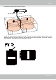
VIVOTEK Hardware Installation Drill a hole on ceiling or wall. The diameters for the installations with or without the retention tube are different. 50mm w/ the retention tube w/o the retention tube 45mm Use the M3 self tapping screws if installed without the retention tube. Note that this type of installation does not apply to hard surfaces, such as a concrete wall. 1. Detach the top cover. 2. Install the retention tube. 3. Route the sensor cable through the hole, and then connect to the lens module.
VIVOTEK Pull the retention clips to the back of the module, and then insert the module into the wall. 4 Extension tube Use an extension tube if the wall is thicker than 6cm. The retention clips will hold the module in place. Note that the shooting angle of a fixed lens can only be vertically adjusted. This mark should be on top.
VIVOTEK Route and connect the R12 sensor cables. Up to 8 meters. RJ12 Install the camera main assembly to wall. Secure the mount bracket to the sides of the assembly, and use the screw holes on the bracket as the drilling template. Drill holes, hammer in the anchors, and install the main assembly to a wall.
VIVOTEK 1. Connect 12V DC power and an Ethernet cable to the network. The camera can also be powered by a PoE connection (up to 11.5W). 2. If preferred, install an SD/SDHC/SDXC card. 3. Connect DI and DO devices. The max. load on a DO pin is 50mA. Reset SD LAN / WAN DI/DO Item 1 2 3 4 LED Status Description Steady Red Power on and system booting Red LED off Powered off Steady Red + blinking Green every 1 sec.
VIVOTEK 1. Use a small-size Phillips screwdriver to change the shooting angle of a fixed focal lens. 2. Remove the protective cap from a fisheye lens. 3. Attach the top cover to lens module by aligning the notch. The magnets will hold the cover in place.
VIVOTEK DI/DO Diagram Please refer to the following illustration for the connection method. GND GND VDC Camera Power Camera Power Input BJT transistor Switch +12 VDC Max. Output Input BJT transistor Relay VDC Switch +12 VDC Output Relay Hardware Reset The reset button is used to reset the system or restore the factory default settings. Sometimes resetting the system can return the camera to normal operation.
VIVOTEK Network Deployment Setting up the Network Camera over the Internet There are several ways to set up the Network Camera over the Internet. The first way is to set up the Network Camera behind a router. The second way is to utilize a static IP. The third way is to use PPPoE. Internet connection via a router Before enabling the access to the Network Camera over the Internet, make sure you have a router and follow the steps below. 1.
VIVOTEK For example, your router and IP settings may look like this: Device IP Address: internal IP Address: External Port (Mapped port on the port router) Public IP of router 122.146.57.120 LAN IP of router 192.168.2.1 Camera 1 192.168.2.10:80 122.146.57.120:8000 Camera 2 192.168.2.11:80 122.146.57.120:8001 ... ... ...
VIVOTEK Internet connection with static IP Choose this connection type if you are required to use a static IP for the Network Camera. Please refer to LAN configuration on page 65 for details. Internet connection via PPPoE (Point-to-Point over Ethernet) Choose this connection type if you are connected to the Internet via a DSL Line. Please refer to PPPoE on page 85 for details.
VIVOTEK General Connection (without PoE) 1. If you have external DI devices, make the connection from general I/O terminal block. 2. Ethernet, power and IO cables are user-supplied. 3. Connect DC power cord to a DC Adapter, and then to a power outlet. 1 3 2 POWER NOTE: The power adapter should comply with L.P.S. regulations featuring O/P: 12V DC, 1.5A min.
VIVOTEK Software Installation Installation Wizard 2 (IW2), free-bundled software included on the product CD, helps you set up your Network Camera on the LAN. 1. Install IW2 under the Software Utility directory from the software CD. Double click the IW2 shortcut on your desktop to launch the program. IW2 Installation Wizard 2 2. The program will conduct an analysis of your network environment. After your network environment is analyzed, please click Next to continue the program. 3.
VIVOTEK Ready to Use 1. A browser session with the Network Camera should prompt as shown below. 2. You should be able to see live video from your camera. You may also install the 32-channel recording software from the software CD in a deployment consisting of multiple cameras. For its installation details, please refer to its related documents.
VIVOTEK Accessing the Network Camera This chapter explains how to access the Network Camera through web browsers, RTSP players, 3GPP-compatible mobile devices, and VIVOTEK recording software. Using Web Browsers IMPORTANT: • Currently the Network Camera utilizes 32-bit ActiveX plugin. You CAN NOT open a management/view session with the camera using a 64-bit IE browser. • If you encounter this problem, try execute the Iexplore.exe program from C:\Windows\ SysWOW64.
VIVOTEK NOTE: For Mozilla Firefox users, your browser will use Quick Time to stream live video. If you do not have Quick Time on your computer, please download Quick Time from Apple Inc's website, and then launch your web browser. Tips: • The onscreen Java control can malfunction under the following situations: A PC connects to different cameras that are using the same IP address (or the same camera running different firmware versions). Removing your browser cookies will solve this problem.
VIVOTEK NOTE: 1. By default, your Network Camera is not password-protected. To prevent unauthorized access, it is highly recommended to configure a password for your camera later. For more information about how to enable password protection, please refer to Security on page 83. 2. If you see a dialogue box indicating that your security settings prohibit running ActiveX Controls®, please enable ActiveX Controls for your browser. To enable the ActiveX® Controls for your browser: 2-1.
VIVOTEK Using RTSP Players To view the H.264 streaming media using RTSP players, you can use one of the following players that support RTSP streaming. Quick Time Player VLC Player 1. Launch the RTSP player. 2. Choose File > Open URL. A URL dialog box will prompt. 3. The address format is rtsp://:/ As most ISPs and players only allow RTSP streaming through port number 554, please set the RTSP port to 554.
VIVOTEK Using 3GPP-compatible Mobile Devices To view the streaming media through 3GPP-compatible mobile devices, make sure the Network Camera can be accessed over the Internet. For more information on how to set up the Network Camera over the Internet, please refer to Setup the Network Camera over the Internet on page 13. To utilize this feature, please check the following settings on your Network Camera: 1.
VIVOTEK Using VIVOTEK Recording Software The product software CD also contains recording software, allowing simultaneous monitoring and video recording for multiple Network Cameras. Please install the recording software; then launch the program to add the Network Camera to the Channel list. For detailed information about how to use the recording software, please refer to the user’s manual of the software or download it from http://www.vivotek.com.
VIVOTEK Main Page This chapter explains the screen elements on the main page. It is composed of the following sections: VIVOTEK INC. Logo, Host Name, Camera Control Area, Configuration Area, and Live Video Window. VIVOTEK logo Resize Buttons Configuration Area Host name Camera Control Panel Live View window VIVOTEK INC. Logo Click this logo to visit the VIVOTEK website. Host Name The host name can be customized to fit your needs.
VIVOTEK NOTE: Skip this section if you do not apply fisheye lens modules in your configuration. Display mode: (This menu only displays when a fisheye lens module is attached) This is a configuration menu exclusively designed for Fisheye lens. Due to the fisheye lens’ wide coverage of 180º hemispheric and 360º panoramic views and to manipulate the details within, the following display modes are provided: 1O - One Original fisheye view.
VIVOTEK 1O (Original) Display mode: When mounted on a ceiling, the fisheye camera can cover an approximately 50 m² of surveillance area (hung at a height of approximately 3 meters), while still keeping details in videos with recognizable facial features of people trafficking through the area. 1O View (Original View) 180° Hemispheric The 1O view is especially adequate for taking an overview glimpse of surveillance area with a ceiling mount camera.
VIVOTEK 1R (Single Regional) Display mode: The 1R mode provides access to one image section within the hemisphere. You can zoom in or out (using the mouse wheel or PTZ panel) or travel to other areas in the hemisphere using mouse clicks and swipes. A single click on a particular object can bring the object to the center of your view window. Click and hold down the left mouse button, and you can swipe the view both horizontally and vertically.
VIVOTEK 1O3R (One Original & Three Regional) Display mode: The 1O3R mode provides access to multiple live view sections within the hemisphere and the reference to their relative positions on an Original circular view. The FOV indicators (#1 ~ #3) interact with your current operation as you may zoom in/out or move the live view window to a different place. You can zoom in or out or travel to other areas within the hemisphere using identical methods as previously described in the 1R mode.
VIVOTEK 4R (Four Regional) Display mode: The view control and look and feel are identical to that as described in the 1O3R mode except the absence of the Original circular view. 4R PRO (Four Regional Proactive) Display mode: The 4R PRO mode is similar to the 4R mode except that the quad view windows consecutively rotate in correspondence to the change of view area in one window. Note that zoom in/out and tilt control is not available in this mode.
VIVOTEK Video Stream: This Network Camera supports multiple streams (channel # and stream #1 ~ #3) simultaneously. You can select any one of them for live viewing. For more information about multiple streams, please refer to page 59 for detailed information. Manual Trigger: Click to manually enable or disable an event trigger. Please configure an event setting before enabling this function. A total of 3 or 4 event settings can be configured.
VIVOTEK Configuration: Click this button to access more of the configuration options provided with the Network Camera. It is suggested that a password is applied to the Network Camera so that only the administrator can configure the Network Camera. For more information, please refer to the description for the Configuration menus on page 41. Language: Click this button to choose a language for the user interface.
VIVOTEK Snapshot: Click this button to capture and save still images. The captured images will be displayed in a pop-up window. Right-click the image and choose Save Picture As to save it in JPEG (*.jpg) or BMP (*.bmp) format. Pause: Pause the transmission of the streaming media. The button becomes the after clicking the Pause button. Stop: Stop the transmission of the streaming media. Click the transmission.
VIVOTEK ■ The following window is displayed when the video mode is set to MJPEG: Video Title Title and Time Video (HTTP-V) 2011/03/10 17:08:56 Time Video 17:08:56 2011/03/10 Video Control Buttons Video Title: The video title can be configured. For more information, please refer to Media > Image on page 52. Time: Display the current time. For more information, please refer to Media > Image on page 52. Title and Time: Video title and time can be stamped on the streaming video.
VIVOTEK User's Manual - 35
VIVOTEK Tips: 1. The onscreen Java control can malfunction under the following situations: A PC connects to different cameras that are using the same IP address (or the same camera running different firmware versions). Removing your browser cookies will solve this problem. 2. If you encounter problems with displaying the configuration menus or UI items, try disable the Compatibility View on IE8 or IE9.
VIVOTEK Client Settings This chapter explains how to select the stream transmission mode and saving options on the local computer. When completed with the settings on this page, click Save on the page bottom to enable the settings. H.264 Media Options Select to stream video or audio data or both. This is enabled only when the video mode is set to H.264. H.264 Protocol Options Depending on your network environment, there are four options with the transmission protocols with H.
VIVOTEK MP4 Saving Options Users can record live video as they are watching it by clicking the “Start MP4 Recording” button on the main page. Here, you can specify the storage destination and file name. Folder: Specify a storage destination for the recorded video files. File name prefix: Enter the text that will be appended to the front of the video file name. Add date and time suffix to the file name: Select this option to append the date and time to the end of the file name.
VIVOTEK Joystick settings Enable Joystick Connect a joystick to a USB port on your management computer. Supported by the plug-in (Microsoft’s DirectX), once the plug-in for the web console is loaded, it will automatically detect if there is any joystick on the computer. The joystick should work properly without installing any other driver or software. Then you can begin to configure the joystick settings of connected devices. Please follow the instructions below to enable joystick settings. 1.
VIVOTEK Buttons Configuration Click the Configure Buttons button, a window will prompt as shown below. Please follow the steps below to configure your joystick buttons: 1. Select a button number from the Button # pull-down menu. Tips If you are not sure of the locations of each button, use the Properties window in the Game Controllers utility. 2. Select a corresponding action, such as Patrol or Preset#. 3. Click the Assign button to assign an action to the button.
VIVOTEK Configuration Click Configuration on the main page to enter the camera setting pages. Note that only Administrators can access the configuration page. VIVOTEK provides an easy-to-use user interface that helps you set up your network camera with minimal effort. In order to simplify the user interface, detailed information will be hidden unless you click on the function item.
VIVOTEK System > General settings This section explains how to configure the basic settings for the Network Camera, such as the host name and system time. It is composed of the following two columns: System and System Time. System Host name: Enter a desired name for the Network Camera. The name will be displayed at the top center of the main page. Turn off the LED indicator: Click to disable the onboard LEDs. System time Time zone : Select the appropriate time zone from the list.
VIVOTEK System > Homepage layout This section explains how to set up your own customized homepage layout. General settings This column shows the settings of your hompage layout. You can manually select the background and font colors in Theme Options (the second tab on this page). The settings will be displayed automatically in this Preview field. The following shows the homepage using the default settings: ■ Hide Powered by VIVOTEK: If you check this item, it will be removed from the homepage.
VIVOTEK Theme Options Here you can change the color of your homepage layout. There are three types of preset patterns for you to choose from. The new layout will simultaneously appear in the Preview filed. Click Save to enable the settings.
VIVOTEK ■ Follow the steps below to set up a custom homepage: 1. Click Custom on the left column. 2. Click to select a color on on the right column. Color Selector Custom Pattern 3. The palette window will pop up as shown below. 2 3 1 4 4. Drag the slider bar and click on the left square to select a desired color. 5. The selected color will be displayed in the corresponding fields and in the Preview column. 6. Click Save to enable the settings.
VIVOTEK System > Logs This section explains how to configure the Network Camera to backup system log to a remote server. Log server settings Follow the steps below to set up the remote log: 1. Select Enable remote log. 2. In the IP address text box, enter the IP address of the remote server. 2. In the port text box, enter the port number of the remote server. 3. When completed, click Save to enable the setting.
VIVOTEK Access log Access log displays the access time and IP address of all viewers (including operators and administrators) in a chronological order. The access log is stored in the Network Camera’s buffer and older events will be overwritten when the number of events reaches a limit. System > Parameters The View Parameters page lists the entire system’s parameters in an alphabetical order. If you need technical assistance, use a text-editor program to copy and save the parameters listed on this page.
VIVOTEK System > Maintenance This chapter explains how to restore the Network Camera to factory default, upgrade firmware version, etc. General settings > Upgrade firmware This feature allows you to upgrade the firmware of your Network Camera. It takes a few minutes to complete the process. Note: Do not power off the Network Camera during the upgrade! Follow the steps below to upgrade the firmware: 1. Download the latest firmware file from the VIVOTEK website. The file is in .pkg file format. 2.
VIVOTEK General settings > Restore This feature allows you to restore the Network Camera to factory default settings. Network: Select this option to retain the Network Type settings (please refer to Network Type on page 65). Daylight Saving Time: Select this option to retain the Daylight Saving Time settings (please refer to Import/Export files below on this page). Custom Language: Select this option to retain the Custom Language settings.
VIVOTEK 3. Open the file with Microsoft® Notepad and locate your time zone; set the start and end time of DST. When completed, save the file. In the example below, DST begins each year at 2:00 a.m. on the second Sunday in March and ends at 2:00 a.m. on the first Sunday in November. Update daylight saving time rules: Click Browse… and specify the XML file to update. If incorrect date and time are assigned, you will see the following warning message when uploading the file to the Network Camera.
VIVOTEK The following message is displayed when attempting to upload an incorrect file format. Export language file: Click to export language strings. VIVOTEK provides nine languages: English, Deutsch, Español, Français, Italiano, 日本語, Português, 簡体中文, and 繁體中文. Update custom language file: Click Browse… and specify your own custom language file to upload. Export configuration file: Click to export all parameters for the device and user-defined scripts.
VIVOTEK Media > Image This section explains how to configure the image settings of the Network Camera. It is composed of the following tabbed windows: General settings, Image settings, Exposure, and Privacy mask, and Pixel Calculator. Channel Selector Since this camera connects to two lens modules, select a video channel first. The corresponding configuration related to each lens module will be displayed.
VIVOTEK Mount type: (Fisheye lens only) There are 3 Mount types - Ceiling, Wall, and Floor. Ceiling: The Ceiling mount type automatically delivers upside-down images. The Ceiling mode supports the following Display modes - 1O, 1P, 1R, 2P, 1O3R, 4R, 4R PRO, and 1O8R. Wall: The Wall mount type applies to the monitoring of long, side-to-side surveillance areas, such as when mounted on a wall facing a corridor. Different Mount types have different options with the Display mode settings.
VIVOTEK Image settings On this page, you can tune the White balance, Image adjustment and WDR enhanced parameters. You can configure two sets of preferred settings: one for normal situations, the other for special situations, such as day/night/schedule mode. Quality: This determines the quality of video feed on the Image settings page. White balance: Adjust the value for the best color temperature.
VIVOTEK ■ Sharpness: Adjust the image sharpness level, which ranges from 0% to 100%. ■ Gamma curve: Adjust the image sharpness level, which ranges from 0.45 to 1, from Detailed to Contrast. You may let firmware Optimize your display or select the Manual mode, and pull the slide bar pointer to change the preferred level of Gamma correction towards higher contrast or towards the higher luminance for detailed expression for both dark and lighted areas of an image.
VIVOTEK Exposure On this page, you can set the Exposure measurement window, Exposure level, Exposure mode, Exposure time, Gain control, and Day/Night mode settings. Measurement Window: This function allows users to set measurement window(s) for low light compensation. For example, where low-light objects are posed against an extremely bright background. You may want to exclude the bright sunlight shining through a building's corridor.
VIVOTEK The inclusive window refers to the “weighed window“; the exclusive window refers to “ignored window“. It adopts the weighed averages method to calculate the value. The inclusive windows have a higher priority. You can overlap these windows, and, if you place an exclusive window within a larger inclusive window, the exclusive part of the overlapped windows will be deducted from the inclusive window. An exposure value will then be calculated out of the remaining of the inclusive window.
VIVOTEK Privacy mask Click Privacy Mask to open the settings page. On this page, you can block out certain sensitive zones to address privacy concerns. 4x ■ To set the privacy mask windows, follow the steps below: 1. Click New to add a new window. A text box will appear allowing you to enter a name for the mask. 2. Use four mouse clicks to mark a square area, which is recommended to be at least twice the size of the object (height and width) you want to cover. 3.
VIVOTEK Media > Video Stream settings Please follow the steps below to set up those settings for an individual stream: 1. Select a stream to configure its viewing region. 2. Choose a proper Frame Size from the drop-down list according to the size of monitored device. 3. Select the Maximum frame rate.
VIVOTEK The Viewing Window (Video Crop) function is only available on the fixed-focal lens module. Click Viewing Window to open the viewing region settings page. On this page, you can set the Region of Interest and the Output Frame Size for stream 1. If you prefer not to stream the full image the sensor can capture, you can designate a smaller region of interest. Please follow the steps below to set up those settings for a stream: 1. Select a stream for which you want to set up the viewing region. 2.
VIVOTEK Click the stream item to display the detailed information. This Network Camera offers real-time H.264 and MJPEG compression standards (dual Codec) for realtime viewing. If the H.264 mode is selected, the video is streamed via RTSP protocol. There are several parameters for you to adjust the video performance: ■ Frame size You can set up different video resolutions for different viewing devices.
VIVOTEK ■ Intra frame period Determine how often to plant an I frame. The shorter the duration, the more likely you will get better video quality, but at the cost of higher network bandwidth consumption. Select the intra frame period from the following durations: 1/4 second, 1/2 second, 1 second, 2 seconds, 3 seconds, and 4 seconds. ■ Video quality • Constant bit rate: A complex scene generally produces a larger file size, meaning that higher bandwidth will be needed for data transmission.
VIVOTEK If JPEG mode is selected, the Network Camera continuously sends JPEG images to the client, producing a moving effect similar to a filmstrip. Every single JPEG image transmitted guarantees the same image quality, which in turn comes at the expense of variable bandwidth usage. Because the media contents are a combination of JPEG images, no audio data is transmitted to the client.
VIVOTEK Media > Audio Audio Settings Mute: Select this option to disable audio transmission from the Network Camera to all clients. Note that if mute mode is turned on, no audio data will be transmitted even if audio transmission is enabled on the Client Settings page. In that case, the following message is displayed: Internal microphone input gain: Select the gain of the internal audio input according to ambient conditions. Adjust the gain from -33dB (least) to 21dB (most).
VIVOTEK Network > General settings This section explains how to configure a wired network connection for the Network Camera. Network Type LAN Select this option when the Network Camera is deployed on a local area network (LAN) and is intended to be accessed by local computers. The default setting for the Network Type is LAN. Rememer to click Save when you complete the Network setting.
VIVOTEK Primary DNS: The primary domain name server that translates hostnames into IP addresses. Secondary DNS: Secondary domain name server that backups the Primary DNS. Primary WINS server: The primary WINS server that maintains the database of computer name and IP address. Secondary WINS server: The secondary WINS server that maintains the database of computer name and IP address.
VIVOTEK NOTE: ► If the default ports are already used by other devices connected to the same router, the Network Camera will select other ports for the Network Camera. ► If UPnP TM is not supported by your router, you will see the following message: Error: Router does not support UPnP port forwarding. ► Below are steps to enable the UPnP TM user interface on your computer: Note that you must log on to the computer as a system administrator to install the UPnP TM components. 1.
VIVOTEK 4. In the Networking Services dialog box, select Universal Plug and Play and click OK. 5. Click Next in the following window. 6. Click Finish. UPnP TM is enabled. ► How does UPnP TM work? UPnP TM networking technology provides automatic IP configuration and dynamic discovery of devices added to a network. Services and capabilities offered by networked devices, such as printing and file sharing, are available among each other without the need for cumbersome network configuration.
VIVOTEK Enable IPv6 Select this option and click Save to enable IPv6 settings. Please note that this only works if your network environment and hardware equipment support IPv6. The browser should be Microsoft® Internet Explorer 6.5, Mozilla Firefox 3.0 or above. When IPv6 is enabled, by default, the network camera will listen to router advertisements and be assigned with a link-local IPv6 address accordingly. IPv6 Information: Click this button to obtain the IPv6 information as shown below.
VIVOTEK Please follow the steps below to link to an IPv6 address: 1. Open your web browser. 2. Enter the link-global or link-local IPv6 address in the address bar of your web browser. 3. The format should be: http://[2001:0c08:2500:0002:0202:d1ff:fe04:65f4]/ IPv6 address 4. Press Enter on the keyboard or click Refresh button to refresh the webpage.
VIVOTEK Port HTTPS port: By default, the HTTPS port is set to 443. It can also be assigned to another port number between 1025 and 65535. FTP port: The FTP server allows the user to save recorded video clips. You can utilize VIVOTEK's Installation Wizard 2 to upgrade the firmware via FTP server. By default, the FTP port is set to 21, or assigned to another port number between 1025 and 65535.
VIVOTEK Network > Streaming protocols HTTP streaming To utilize HTTP authentication, make sure that your have set a password for the Network Camera first; please refer to Security > User account on page 83 for details. Authentication: Depending on your network security requirements, the Network Camera provides two types of security settings for an HTTP transaction: basic and digest.
VIVOTEK URL command -- http://:/ For example, when the Access name for stream 2 is set to video2.mjpg: 1. Launch Mozilla Firefox or Netscape. 2. Type the above URL command in the address bar. Press Enter. 3. The JPEG images will be displayed in your web browser. http://192.168.5.151/video2.
VIVOTEK Authentication: Depending on your network security requirements, the Network Camera provides three types of security settings for streaming via RTSP protocol: disable, basic, and digest. If basic authentication is selected, the password is sent in plain text format, but there can be potential risks of it being intercepted. If digest authentication is selected, user credentials are encrypted using MD5 algorithm, thus providing better protection against unauthorized access.
VIVOTEK RTSP port /RTP port for video, audio/ RTCP port for video, audio ■ RTSP (Real-Time Streaming Protocol) controls the delivery of streaming media. By default, the port number is set to 554. ■ The RTP (Real-time Transport Protocol) is used to deliver video and audio data to the clients. By default, the RTP port for video is set to 5556 and the RTP port for audio is set to 5558.
VIVOTEK Multicast settings for channel # and stream 1 ~ 3: Click the items to display the detailed configuration information. Select the Always multicast option to enable multicast for streams 1 ~ 3. Unicast video transmission delivers a stream through point-to-point transmission; multicast, on the other hand, sends a stream to the multicast group address and allows multiple clients to acquire the stream at the same time by requesting a copy from the multicast group address.
VIVOTEK Network > DDNS This section explains how to configure the dynamic domain name service for the Network Camera. DDNS is a service that allows your Network Camera, especially when assigned with a dynamic IP address, to have a fixed host and domain name. Manual setup DDNS: Dynamic domain name service Enable DDNS: Select this option to enable the DDNS setting. Provider: Select a DDNS provider from the provider drop-down list. VIVOTEK offers Safe100.
VIVOTEK 3. Click Copy and all the registered information will automatically be uploaded to the corresponding fields in the DDNS column at the top of the page as seen in the picture. [Register] Successfully Your account information has been mailed to registered e-mail address 4. Select Enable DDNS and click Save to enable the setting. ■ CustomSafe100 VIVOTEK offers documents to establish a CustomSafe100 DDNS server for distributors and system integrators.
VIVOTEK Express link Express Link is a free service provided by VIVOTEK server, which allows users to register a domain name for a network device. One URL can only be mapped to one MAC address. This service will examine if the host name is valid and automatically open a port on your router. If using DDNS, the user has to manually configure UPnP port forwarding. Express Link is more convenient and easier to set up. Please follow the steps below to enable Express Link: 1.
VIVOTEK Network > QoS (Quality of Service) Quality of Service refers to a resource reservation control mechanism, which guarantees a certain quality to different services on the network. Quality of service guarantees are important if the network capacity is insufficient, especially for real-time streaming multimedia applications. Quality can be defined as, for instance, a maintained level of bit rate, low latency, no packet dropping, etc.
VIVOTEK QoS/DSCP (the DiffServ model) DSCP-ECN defines QoS at Layer 3 (Network Layer). The Differentiated Services (DiffServ) model is based on packet marking and router queuing disciplines. The marking is done by adding a field to the IP header, called the DSCP (Differentiated Services Codepoint). This is a 6-bit field that provides 64 different class IDs. It gives an indication of how a given packet is to be forwarded, known as the Per Hop Behavior (PHB).
VIVOTEK Network > SNMP (Simple Network Management Protocol) This section explains how to use the SNMP on the network camera. The Simple Network Management Protocol is an application layer protocol that facilitates the exchange of management information between network devices. It helps network administrators to remotely manage network devices and find, solve network problems with ease. ■ The SNMP consists of the following three key components: 1.
VIVOTEK Security > User Account This section explains how to enable password protection and create multiple accounts. Root Password The administrator account name is “root”, which is permanent and can not be deleted. If you want to add more accounts in the Manage User column, please apply the password for the “root” account first. 1. Type the password identically in both text boxes, then click Save to enable password protection. 2.
VIVOTEK Security > HTTPS (Hypertext Transfer Protocol over SSL) This section explains how to enable authentication and encrypted communication over SSL (Secure Socket Layer). It helps protect streaming data transmission over the Internet on higher security level. Create and Install Certificate Method Before using HTTPS for communication with the Network Camera, a Certificate must be created first. There are three ways to create and install a certificate: Create self-signed certificate 1.
VIVOTEK 5. Click Save to preserve your configuration, and your current session with the camera will change to the encrypted connection. 6. If your web session does not automatically change to an encrypted HTTPS session, click Home to return to the main page. Change the URL address from “http://” to “https://“ in the address bar and press Enter on your keyboard. Some Security Alert dialogs will pop up. Click OK or Yes to enable HTTPS.
VIVOTEK Create certificate request and install 1. Select the option from the Method pull-down menu. 2. Click Create certificate to proceed. 3. The following information will show up in a pop-up window after clicking Create. Then click Save to generate the certificate request. 4. The Certificate request window will prompt. If you see the following Information bar, click OK and click on the Information bar at the top of the page to allow pop-ups.
VIVOTEK 5. Look for a trusted certificate authority, such as Symantec’s VeriSign Authentication Services, that issues digital certificates. Sign in and purchase the SSL certification service. Copy the certificate request from your request prompt and paste it in the CA’s signing request window. Proceed with the rest of the process as CA’s instructions on their webpage. 6. Once completed, your SSL certificate should be delivered to you via an email or other means.
VIVOTEK 7. Open a new edit, paste the certificate contents, and press ENTER at the end of the contents to add an empty line. 8. Convert file format from DOS to UNIX. Open File menu > Conversions > DOS to Unix.
VIVOTEK 9. Save the edit using the “.crt” extension, using a file name like “CAcert.crt.” 10. Return to the original firmware session, use the Browse button to locate the crt certificate file, and click Upload to enable the certification.
VIVOTEK 11. When the certifice file is successfully loaded, its status will be stated as Active. Note that a certificate must have been created and installed before you can click on the “Save" button for the configuration to take effect. 12.To begin an encrypted HTTPS session, click Home to return to the main page. Change the URL address from “http://” to “https://“ in the address bar and press Enter on your keyboard. Some Security Alert dialogs will pop up. Click OK or Yes to enable HTTPS.
VIVOTEK Security > Access List This section explains how to control access permission by verifying the client PC’s IP address. General Settings Maximum number of concurrent streaming connection(s) limited to: Simultaneous live viewing for 1~10 clients (including stream #1, #2, and #3). The default value is 10. If you modify the value and click Save, all current connections will be disconnected and automatically attempt to re-link (IE Explorer or Quick Time Player).
VIVOTEK ■ Disconnect: If you want to break off the current connections, please select them and click this button. Please note that those checked connections will only be disconnected temporarily and will automatically try to re-link again (IE Explorer or Quick Time Player). Enable access list filtering: Check this item and click Save if you want to enable the access list filtering function. Filter Filter type: Select Allow or Deny as the filter type.
VIVOTEK Network: This rule allows the user to assign a network address and corresponding subnet mask to the Allow/Deny List. The routing prefix is written in CIDR notation. For example: accesses from IP address 192.168.2.x will be bolcked. If IPv6 filter is preferred, you will be prompted by the following window. Enter the IPv6 address and the two-digit prefix length to specify the range of IP addresses in your configuration.
VIVOTEK Security > IEEE 802.1x Enable this function if your network environment uses IEEE 802.1x, which is a port-based network access control. The network devices, intermediary switch/access point/hub, and RADIUS server must support and enable 802.1x settings. The 802.1x standard is designed to enhance the security of local area networks, which provides authentication to network devices (clients) attached to a network port (wired or wireless).
VIVOTEK 3. When all settings are complete, move the Network Camera to the protected LAN by connecting it to an 802.1x enabled switch. The devices will then start the authentication automatically. NOTE: ► The authentication process for 802.1x: 1. The Certificate Authority (CA) provides the required signed certificates to the Network Camera (the supplicant) and the RADIUS Server (the authentication server). 2. A Network Camera requests access to the protected LAN using 802.
VIVOTEK PTZ > PTZ settings Advanced Mode This section explains how to control the Network Camera’s Pan/Tilt/Zoom operation. The PTZ function allows users to quickly move the focus to a target area for close-up viewing without physically zooming the camera. Digital PTZ Operation (E-PTZ Operation) 1 Zoom In Zoom Out 2 4 3 5 6 11 11 8 7 9 Preset positions and rotation settings In the PTZ settings page, you can create preset positions in the hemisphere covered by the fisheye lens.
VIVOTEK 2. Adjust the shooting area to the desired position using the PTZ keypad, the FOV indicators, or mouse clicks on the live screen. To begin the mouse control, click on the two interactive windows. If you click on the Original view window, an FOV indicator will appear. You can click and hold down the left mouse button to drag the FOV indicator to a desired position. The rest of mouse control methods are identical to those for the Regional windows.
VIVOTEK Home page in Regional Display Mode Shown below is the display order of preset positions when you click on the Patrol button on the main page. Preset positions 3 4 56 7 ■ The preset positions will also be displayed on the home page. Select one from the Go to drop-down list, and the preset position will display on one of the Regional view windows. ■ If you have set up different preset positions for different streams, you can select one of the video streams to display its distinctive positions.
VIVOTEK Event > Event settings This section explains how to configure the Network Camera to respond to particular situations (event). A typical application is that when a motion is detected, the Network Camera sends buffered images to an FTP server or e-mail address as notifications. Click on Help, there is an illustration shown in the pop-up window explaining that an event can be triggered by many sources, such as motion detection or external digital input devices.
VIVOTEK ■ Event name: Enter a name for the event setting. ■ Enable this event: Select this checkbox to enable the event setting. ■ Priority: Select the relative importance of this event (High, Normal, or Low). Events with a higher priority setting will be executed first. seconds: Enter the duration in seconds to pause ■ Detect next motion detection or digital input after motion detection after a motion is detected. This prevents too many events to be triggered within a short time.
VIVOTEK ■ Camera tampering detection This option allows the Network Camera to trigger when the camera detects that is is being tampered with. To enable this function, you need to configure the Tampering Detection option first. Please refer to page 116 for detailed information. ■ Manual Trigger This option allows user to enable event triggers manually by clicking the on/off button on the homepage. Please configure 1 ~ 3 events before using this function.
VIVOTEK 3. Action Define the actions to be performed by the Network Camera when a trigger is activated. ■ Trigger digital output for seconds Select this option to turn on the digital output signals (via the DO connectors on the main assembly) when a trigger is activated. Specify the length of the trigger interval in the text box. ■ Backup media if the network is disconnected Select this option to backup media file on SD card if the network is disconnected.
VIVOTEK Add server Click Add server to unfold the server setting window. You can specify how the notification messages are delivered when a trigger is activated. A total of 5 server settings can be configured. There are four choices of server types available: Email, FTP, HTTP, and Network storage. Select the item to display the detailed configuration options. You can configure either one or all of them. Server type - Email Select to send the media files via email when a trigger is activated.
VIVOTEK To verify if the email settings are correctly configured, click Test. The result will be shown in a pop-up window. If successful, you will also receive an email indicating the result. Click Save server to enable the settings, then click Close to exit the Add server page. After you set up the first event server, a new item for event server will automatically appear on the Server list. If you wish to add more server options, click Add server.
VIVOTEK ■ Passive mode Most firewalls do not accept new connections initiated from external requests. If the FTP server supports passive mode, select this option to enable passive mode FTP and allow data transmission to pass through the firewall. To verify if the FTP settings are correctly configured, click Test. The result will be shown in a pop-up window as shown below. If successful, you will also receive a test.txt file on the FTP server.
VIVOTEK Network storage: Select to send the media files to a network storage location when a trigger is activated. Please refer to NAS server on page 119 for details. Click Save server to enable the settings, then click Close to exit the Add server page. ■ SD Test: Click to test your SD card. The system will display a message indicating success or failure. If you want to use your SD card for local storage, please format it before use. Please refer to page 122 for detailed information.
VIVOTEK Add media Click Add media to open the media setting window. You can specify the type of media that will be sent when a trigger is activated. A total of 5 media settings can be configured. There are three choices of media types available: Snapshot, Video Clip, and System log. Select the item to display the detailed configuration options. You can configure either one or all of them. Media type - Snapshot Select to send snapshots when a trigger is activated.
VIVOTEK ■ Add date and time suffix to the file name. Select this option to add a date/time suffix to the file name. For example: Snapshot_20140720_100341 File name prefix Date and time suffix The format is: YYYYMMDD_HHMMSS Click Save media to enable the settings, then click Close to exit the Add media page. After you set up the first media server, a new column for media server will automatically display on the Media list. If you wish to add more media options, click Add media.
VIVOTEK ■ Maximum duration Specify the maximum recording duration in seconds. Up to 10 seconds of video can be recorded. For example, if pre-event recording is set to 5 seconds and the maximum duration is set to 10 seconds, the Network Camera continues to record for another 4 seconds after a trigger is activated. 1 sec. 2 sec. 3 sec. 4 sec. 5 sec. 6 sec. 7 sec. 8 sec. 9 sec. 10 sec. Trigger Activation ■ Maximum file size Specify the maximum file size allowed.
VIVOTEK ■ View: Click this button to open a file list window. This function is only for SD card and Network Storage. If you click View button of SD card, a Local storage page will pop up for you to manage recorded files on SD card. For more information about Local storage, please refer to page 122. If you click View button of Network storage, a file directory window will pop up for you to view recorded data on Network storage.
VIVOTEK Here is an example of the Event setting: When completed the settings with steps 1~3 to arrange Schedule, Trigger, and Action of an event, click Save event to enable the settings and click Close to exit the page.
VIVOTEK When the Event Status is ON, once an event is triggered by motion detection, the Network Camera will automatically send snapshots via e-mail. If you want to stop the event trigger, you can click ON to turn it to OFF status or click Delete to remove a previously-configured event setting. To remove a server setting from the list, select a server name and click Delete. Note that only when the server setting is not being applied to an event setting can it be deleted.
VIVOTEK Applications > Motion detection This section explains how to configure the Network Camera to enable motion detection. A total of five motion detection windows can be configured. 4x Follow the steps below to enable motion detection: 1. Click New to add a new motion detection window. 2. In the Window Name text box, enter a name for the motion detection window. ■ Use four mouse clicks to define the area where Motion Detection will take effect.
VIVOTEK on page 99. A green bar indicates that even though motions have been detected, the event has not been triggered because the image variations still fall under the defined threshold. Percentage = 30% This motion detection window will also be displayed on the Event settings page. You can go to Event > Event settings > Trigger to choose it as a trigger source. Please refer to page 100 for detailed information.
VIVOTEK NOTE: ► How does motion detection work? A C B D There are two motion detection parameters: Sensitivity and Percentage. In the illustration above, frame A and frame B are two sequential images. Pixel differences between the two frames are detected and highlighted in gray (frame C) and will be compared with the sensitivity setting. Sensitivity is a value that expresses the sensitivity to moving objects.
VIVOTEK Applications > DI and DO Digital input: Select High or Low as the Normal status for the digital input. Connect the digital input pin of the Network Camera to an external device to detect the current connection status. Digital output: Select Grounded or Open to define the normal status for the digital output. Connect the digital output pin of the Network Camera to an external device to determine the current status. Set up the event source as DI on Event > Event settings > Trigger.
VIVOTEK Recording > Recording settings This section explains how to configure the recording settings for the Network Camera. Recording Settings Insert your SD card and click here to test NOTE: 1. Each Recording setting records a video stream from one channel, i.e., from a single lens module. 2. Please remember to format your SD card when used for the first time. Please refer to page 122 for detailed information. Recording Settings Click Add to open the recording setting window.
VIVOTEK ■ Recording name: Enter a name for the recording setting. ■ Enable this recording: Select this option to enable video recording. ■ With adaptive recording: Select this option will activate the frame rate control according to alarm trigger. The frame control means that when there is a triggered alarm/event, the frame rate will raise up to the value you’ve set on the Stream setting page. Please refer to page 59 for more information.
VIVOTEK Please follow steps 1~2 below to set up the recording: 1. Trigger Select a trigger source. ■ Schedule: The server will start to record files on the local storage or network attached storage (NAS). ■ Network fail: Since network fail, the server will start to record files onto the local storage (SD card). 2. Destination You can select the SD card or network storage (NAS) for the recorded video files.
VIVOTEK 2. Click Test to check the setting. The result will be shown in the pop-up window. If successful, you will receive a test.txt file on the networked storage server. 3. Enter a server name. 4. Click Save to complete the settings and click Close to exit the page. ■ Capacity: You can either choose the entire available space or impose a reserved space. The Reserved space should be of the size of at least 15MBytes.
VIVOTEK ■ Enable cyclic recording: If you check this item, when the maximum capacity is reached, the oldest file will be overwritten by the latest one. Recording file management ■ Maximum duration: This determines the length of each recorded video, applicable from 1 to 60 minutes. ■ Maximum file size: This determines the file size of each concluded recording. The applicable sizes range from 100 to 2000 Megabytes. ■ File name prefix: Enter a name for each recorded video.
VIVOTEK Local storage > SD card management This section explains how to manage the local storage on the Network Camera. Here you can view SD card status, and implement SD card control. SD card staus This column shows the status and reserved space of your SD card. Please remember to format the SD card when using for the first time. no SD card SD card control ■ Enable cyclic storage: Check this item if you want to enable cyclic recording.
VIVOTEK Local storage > Content management This section explains how to manage the content of recorded videos on the Network Camera. Here you can search and view the records and view the searched results. Searching and Viewing the Records This column allows the user to set up search criteria for recorded data. If you do not select any criteria and click Search button, all recorded data will be listed in the Search Results cloumn. ■ File attributes: Select one or more items as your search criteria.
VIVOTEK Search Results The following is an example of search results. There are four columns: Trigger time, Media type, Trigger type, and Locked. Click to sort the search results in either direction. Numbers of entries displayed on one page Enter a key word to filter the search results Highlight an item ■ View: Click on a search result which will highlight the selected item in purple as shown above. Click the View button and a media window will pop up to play back the selected file.
VIVOTEK ■ JPEGs to AVI: This function only applies to “JPEG“ format files such as snapshots. You can select several snapshots from the list, then click this button. Those snapshots will be converted into an AVI file. ■ Lock/Unlock: Select the desired search results, then click this button. The selected items will become Locked, which will not be deleted during cyclic recoroding. You can click again to unlock the selections.
VIVOTEK Appendix URL Commands for the Network Camera 1. Overview For some customers who already have their own web site or web control application, the Network Camera/Video Server can be easily integrated through URL syntax. This section specifies the external HTTP-based application programming interface. The HTTP-based camera interface provides the functionality to request a single image, control camera functions (PTZ, output relay etc.), and get and set internal parameter values.
VIVOTEK 3. General CGI URL Syntax and Parameters CGI parameters are written in lower-case and as one word without any underscores or other separators. When the CGI request includes internal camera parameters, these parameters must be written exactly as they are named in the camera or video server. The CGIs are organized in functionally-related directories under the cgi-bin directory. The file extension .cgi is required. Syntax: http:///cgi-bin/[/...]/.
VIVOTEK [&…] http:///cgi-bin/operator/getparam.cgi?[] [&…] http:///cgi-bin/admin/getparam.cgi?[] [&…] Where the should be [_] or [.]. If you do not specify any parameters, all the parameters on the server will be returned. If you specify only , the parameters of the related group will be returned. When querying parameter values, the current parameter values are returned.
VIVOTEK 6. Set Server Parameter Values Note: The access right depends on the URL directory. Method: GET/POST Syntax: http:///cgi-bin/anonymous/setparam.cgi? = [&=…][&update=][&return=] http:///cgi-bin/viewer/setparam.cgi? = [&=…][&update=] [&return=] http:///cgi-bin/operator/setparam.
VIVOTEK =\r\n [] Only the parameters that you set and are readable will be returned. Example: Set the IP address of server to 192.168.0.123: Request: http://myserver/cgi-bin/admin/setparam.cgi?network_ipaddress=192.168.0.123 Response: HTTP/1.0 200 OK\r\n Content-Type: text/html\r\n Context-Length: 33\r\n \r\n network.ipaddress=192.168.0.123\r\n 7.
VIVOTEK integer primary key SQLite data type. A 32-bit signed integer. The value is assigned a unique integer by the server. text SQLite data type. The value is a text string, stored using the database encoding (UTF-8, UTF-16BE or UTF-16-LE). coordinate x, y coordinate (eg. 0,0) window size window width and height (eg. 800x600) NOTE: The camera should not be restarted when parameters are changed.
VIVOTEK 7.1 system Group: system NAME VALUE DEFAULT SECURITY DESCRIPTION (get/set) hostname string[64] Mega-Pixel 1/6 Host name of server Network (Network Camera, Camera Wireless Network Camera, Video Server, Wireless Video Server). ledoff 0 6/6 Turn on (0) or turn off (1) all led indicators. date , date> 6/6 Current date of system. Set to ‘keep’ to keep date unchanged. Set to ‘auto’ keep, to use NTP to synchronize date.
VIVOTEK -281: GMT-07:00 Arizona -240: GMT-06:00 Central America, Central Time, Mexico City, Saskatchewan -200: GMT-05:00 Eastern Time, New York, Toronto -201: GMT-05:00 Bogota, Lima, Quito, Indiana -180: GMT-04:30 Caracas -160: GMT-04:00 Atlantic Time, Canada, La Paz, Santiago -140: GMT-03:30 Newfoundland -120: GMT-03:00 Brasilia, Buenos Aires, Georgetown, Greenland -80: GMT-02:00 Mid-Atlantic -40: GMT-01:00 Azores, Cape_Verde_IS.
VIVOTEK 200: GMT 05:00 Ekaterinburg, Islamabad, Karachi, Tashkent 220: GMT 05:30 Calcutta, Chennai, Mumbai, New Delhi 230: GMT 05:45 Kathmandu 240: GMT 06:00 Almaty, Novosibirsk, Astana, Dhaka, Sri Jayawardenepura 260: GMT 06:30 Rangoon 280: GMT 07:00 Bangkok, Hanoi, Jakarta, Krasnoyarsk 320: GMT 08:00 Beijing, Chongging, Hong Kong, Kuala Lumpur, Singapore, Taipei 360: GMT 09:00 Osaka, Sapporo, Tokyo, Seoul, Yakutsk 380: GMT 09:30 Adelaide, Darwin 400: GMT 10:00 Brisbane, Canberra, Melbourne, Sydney, Guam,
VIVOTEK 81,82,83, 120,140, 380,400,48 0 updateinterval 0, 0 6/6 0 to Disable automatic time 3600, adjustment, otherwise, it indicates 86400, the seconds between NTP automatic 604800, update intervals. 2592000 restore 0, N/A 7/6 seconds. integer> reset 0, N/A 7/6 seconds if is non-negative.
VIVOTEK the default value except for a union of the combined results. 7.1.1 system.info Subgroup of system: info (The fields in this group are unchangeable.) NAME VALUE DEFAULT SECURITY DESCRIPTION (get/set) modelname string[40] VC8201 0/7 Internal model name of the server (eg. IP7139) extendedmodelname string[40] VC8201 0/7 ODM specific model name of server (eg. DCS-5610).
VIVOTEK 7.2 status Group: status NAME VALUE DEFAULT SECURITY DESCRIPTION (get/set) di_i<0~(ndi-1)> 0 1/7 0 => Inactive, normal 1 => Active, triggered (capability.ndi > 0) do_i<0~(ndo-1)> 0 1/7 0 => Inactive, normal 1 => Active, triggered (capability.ndo > 0) onlinenum_rtsp integer 0 6/7 Current number of RTSP connections. onlinenum_httppush integer 0 6/7 Current number of HTTP push server connections.
VIVOTEK 7.5 security Group: security NAME VALUE DEFAULT SECURITY DESCRIPTION (get/set) privilege_do view, operator, operator 1/6 admin Indicate which privileges and above can control digital output (capability.ndo > 0) privilege_camctrl view, operator, view 1/6 admin Indicate which privileges and above can control PTZ (capability.ptzenabled > 0 or capability.
VIVOTEK service port to the port occupied by another service currently. Otherwise, the service may fail. Stopped service will auto-start after changing port settings. Ex: Change HTTP port from 80 to 5556, and change RTP port for video from 5556 to 20480. Then, set preprocess=9 to stop both service first. ”/cgi-bin/admin/setparam.cgi? network_preprocess=9&networ k_http_port=5556& network_rtp_videoport=20480” type lan, lan 6/6 Network connection type.
VIVOTEK identity_tls String[64] 6/6 TLS identity password String[253] 6/6 Password for TLS privatekeypassword String[253] 6/6 Password for PEAP ca_exist 0 6/6 CA installed flag ca_time 0 6/7 CA installed time. Represented in EPOCH ca_size 0 6/7 CA file size (in bytes) certificate_exist 0 6/6 Certificate installed flag (for TLS) certificate_time 0 6/7 Certificate installed time.
VIVOTEK (capability.naudio > 0) eventalarm 0~63 0 6/6 Event/alarm channel for DSCP management 0~63 0 6/6 Management channel for DSCP eventtunnel 0~63 0 6/6 Event/Control channel for DSCP SECURITY DESCRIPTION 7.6.3 IPV6 Subgroup of network: ipv6 (capability.protocol.ipv6 > 0) NAME VALUE DEFAULT (get/set) enable 0 6/6 Enable IPv6. addonipaddress 6/6 IPv6 IP address. addonprefixlen 0~128 64 6/6 IPv6 prefix length.
VIVOTEK g =1 and capability.nmediastream > 0) s1_accessname string[32] videos2.mjpg 1/6 HTTP server push access name for stream 2. (capability.protocol.spush_mjpe g =1 and capability.nmediastream > 1) s2_accessname string[32] videos3.mjpg 1/6 Http server push access name for stream 3 (capability.protocol.spush_mjpe g =1 and capability.nmediastream > 2) S3_accessname string[32] Video2.mjpg 1/6 Http server push access name for stream 4 (capability.protocol.spush_mjpe g =1 and capability.
VIVOTEK 7.6.7 RTSP Subgroup of network: rtsp (capability.protocol.rtsp > 0) NAME VALUE DEFAULT SECURITY DESCRIPTION (get/set) port 554, 1025 ~ 554 1/6 65535 anonymousviewing RTSP port. (capability.protocol.rtsp=1) 0 1/6 Enable anoymous streaming viewing. authmode disable, basic 1/6 basic, RTSP authentication mode. (capability.protocol.rtsp=1) digest s0_accessname string[32] live.sdp 1/6 RTSP access name for stream1. (capability.protocol.rtsp=1 and capability.
VIVOTEK 7.6.7.1 RTSP multicast Subgroup of network_rtsp_s<0~(n-1)>: multicast, n is stream count (capability.protocol.rtp.multicast > 0) NAME VALUE DEFAULT SECURITY DESCRIPTION (get/set) alwaysmulticast 0 4/4 Enable always multicast. ipaddress For n=0, 4/4 Multicast IP address. 239.128.1.99 For n=1, 239.128.1.10 0, and so on. videoport 1025 ~ 65535 5560+n*2 4/4 Multicast video port. audioport 1025 ~ 65535 5562+n*2 4/4 Multicast audio port. (capability.
VIVOTEK 7.7 IP Filter Group: ipfilter NAME VALUE DEFAULT SECURITY DESCRIPTION (get/set) enable 0 6/6 Enable access list filtering. admin_enable 0 6/6 Enable administrator IP address. admin_ip String[43] 6/6 Administrator IP address. maxconnection 0~10 10 6/6 Maximum number of concurrent streaming connection(s). type 0, 1 1 6/6 Ipfilter policy : 0 => allow 1 => deny ipv4list_i<0~9> Single 6/6 IPv4 address list.
VIVOTEK rbgain balance. “manual” indicates keep current value. “rbgain” indicates using rgain and gbain. rgain 0~100 50 1/4 Manual set rgain value of gain control setting. bgain 0~100 50 1/4 Manual set bgain value of gain control setting. exposurelevel CU8131: CU8131: 4 0~8 CU8171: 6 1/4 Exposure level 1/4 Enable backlight compensation. CU8171: 0~12 enableblc 0~1 0 (Only used in CU8171) maxgain 0~100 CU8131: 50 1/4 CU8171: 100 mingain 0~100 0 Manual set maximum gain value.
VIVOTEK operation; 0(not support), 1(support) mirror 0 1/4 Mirror the image. text string[64] 1/4 Enclose caption. imprinttimestamp 0 1/4 Overlay time stamp on video. textonvideo_position top, bottom top 1/4 Text on video string position textonvideo_size 15, 25, 30 15 1/4 Text on video font size exposuremode auto,fixed auto 1/4 Exposure mode maxexposure 1~32000 30 1/4 Maximum exposure time.
VIVOTEK input setting. 1 = worst quality, 5 = best quality. 100 is percentage mode. s<0~(m-1)>_h264_qvalue 0~51 30 1/4 Manual video quality level input. (s<0~(m-1)>_h264_quant = 99) s<0~(m-1)>_h264_qperc 1~100 50 1/4 ent Manual video quality level input. (s<0~(m-1)>_h264_quant = 100) s<0~(m-1)>_h264_bitrate 20000~40000 CU8131: 1/4 Set bit rate in bps when 000 3000000 choosing cbr in CU8171: “ratecontrolmode”.
VIVOTEK t 99, 100 99 is the customized manual input setting. 1 = worst quality, 5 = best quality. 100 is percentage mode. s<0~(m-1)>_mjpeg_qvalu 2~97 50 1/4 e Manual video quality level input. (s<0~(m-1)>_mjpeg_quant = 99) s<0~(m-1)>_mjpeg_qper 1~100 50 1/4 cent Manual video quality level input. (s<0~(m-1)>_mjpeg_quant = 100) s<0~(m-1)>_mjpeg_bitrat 1000~400000 CU8131: 1/4 Set bit rate in bps when e 00 6000000 choosing cbr in CU8171: “ratecontrolmode”.
VIVOTEK 7.9 Image setting per channel Group: image_c<0~(n-1)> for n channel products NAME VALUE DEFAULT SECURITY DESCRIPTION (get/set) brightness -5~5,100 100 4/4 Adjust brightness of image. 100 is percentage mode. brightnesspercent 0~100 0 4/4 Adjust brightnesspercent of image when brightness=100. saturation -5~5,100 100 4/4 Adjust saturation of image. 100 is percentage mode. saturationpercent 0~100 50 4/4 Adjust saturation value of percentage when saturation=100.
VIVOTEK 7.10 Exposure window setting per channel Group: exposurewin_c<0~(n-1)> for n channel products NAME VALUE DEFAULT SECURITY DESCRIPTION (get/set) mode auto, custom, auto 4/4 blc The mode indicates how to decide the exposure. auto: Use full view as the only one exposure window. custom: Use inclusive and exclusive window. blc: Use BLC. win_i<0~9>_enable CU8131: 1 4/4 Enable or disable the window. 4/4 0: Indicate exclusive.
VIVOTEK bitstreampackingmode mode. 7.12 Time Shift settings Group: timeshift, c for n channel products, m is stream number (capability.timeshift > 0) NAME VALUE DEFAULT SECURITY DESCRIPTION (get/set) enable 0 4/4 Enable time shift streaming. c<0~(n-1)>_s<0~(m-1)> 0 4/4 Enable time shift streaming for _allow specific stream. 7.
VIVOTEK ‘duration’ second(s), then tamper detection is triggered. 7.15 DDNS Group: ddns (capability.ddns > 0) NAME VALUE DEFAULT SECURITY DESCRIPTION (get/set) enable 0 6/6 Enable or disable the dynamic DNS. provider CustomSafe10 DyndnsDynam 0, ic 6/6 Safe100 => safe100.net DyndnsDynamic => dyndns.org DynInterfree, (dynamic) DyndnsDynam DyndnsCustom => dyndns.org ic, DynInterfree =>dyn-interfree.
VIVOTEK url string[63] NULL 6/6 The url user define to link to camera 7.17 UPnP presentation Group: upnppresentation NAME VALUE DEFAULT SECURITY DESCRIPTION (get/set) enable 1 6/6 Enable or disable the UPnP presentation service. 7.18 UPnP port forwarding Group: upnpportforwarding NAME VALUE DEFAULT SECURITY DESCRIPTION (get/set) enable 0 6/6 Enable or disable the UPnP port forwarding service.
VIVOTEK 5: LOG_NOTICE 6: LOG_INFO 7: LOG_DEBUG setparamlevel 0~2 0 6/6 Show log of parameter setting. 0: disable 1: Show log of parameter setting set from external. 2. Show log of parameter setting set from external and internal. 7.20 SNMP Group: snmp (capability.snmp > 0) NAME VALUE DEFAULT SECURITY DESCRIPTION (get/set) v2 0~1 0 6/6 SNMP v2 enabled. 0 for disable, 1 for enable v3 0~1 0 6/6 SNMP v3 enabled.
VIVOTEK 7.21 Layout configuration Group: layout (New version) NAME VALUE DEFAULT SECURITY DESCRIPTION (get/set) logo_default 1 1/6 0 => Custom logo 1 => Default logo logo_link string[128] http://www.vi 1/6 Hyperlink of the logo 1/6 0 => display the power by votek.
VIVOTEK win_i<0~4>_name string[40] 4/4 Name of the privacy mask window. win_i<0~4>_polygon 0 ~ 320,0 ~ 0 4/4 Coordinate of polygon window 240, 0 ~ 320,0 position. ~ 240, 0 ~ (4 points: 320,0 ~ 240, 0 x0,y0,x1,y1,x2,y2,x3,y3) ~ 320,0 ~ 240 7.23 Capability Group: capability NAME VALUE DEFAULT SECURITY DESCRIPTION (get/set) api_httpversion 0301a 0/7 The HTTP API version. bootuptime
VIVOTEK nvideoout nanystream 0, nmediastream nmotion naudiosetting nuart 0, channel. 0 0/7 Number of UART interfaces. 0 0/7 Number of video input profiles. 5 0/7 Number of privacy masks.
VIVOTEK 0(not support), 1(support) Bit 6 => Support iris operation; 0(not support), 1(support) Bit 7 => External or built-in PT; 0(built-in), 1(external) Bit 8 => Invalidate bit 1 ~ 7; 0(bit 1 ~ 7 are valid), 1(bit 1 ~ 7 are invalid) Bit 9 => Reserved bit; Invalidate lens_pan, Lens_tilt, lens_zoon, lens_focus, len_iris. 0(fields are valid), 1(fields are invalid) windowless 1 0/7 Indicate whether to support windowless plug-in.
VIVOTEK protocol_rtp_http 1 0/7 Indicate whether to support RTP over HTTP. protocol_spush_mjpeg 1 0/7 Indicate whether to support server push MJPEG. protocol_snmp 1 0/7 Indicate whether to support SNMP. protocol_ipv6 1 0/7 Indicate whether to support IPv6. protocol_pppoe 1 0/7 Indicate whether to support PPPoE. protocol_ieee8021x 1 0/7 Indicate whether to support IEEE802.1x.
VIVOTEK CU8171: CU8171_VC82 01 videoin_c<0~1>_streamco one stands for a stream, and the definition is as following: Bit 0: Support MPEG4. Bit 1: Support MJPEG Bit 2: Support H.
VIVOTEK videoin_c<0~1>_maxfram 15,15,15,15,1 "resolution" parameter in this 5,15,15,15 group. - 0/7 0/7 Indicate maximum frame rate videoin_c<0~1>_mpeg4_
VIVOTEK commas> 1280x720, 1280x800 CU8171: 192x192, 256x256, 384x384, 512x512, 768x768, 1056x1056, 1536x1536, 1696x1696 videoin_c<0~1>_mode0_ effectivepixel CU8131: 0/7 The visible area of full scene in 1280x800 this video mode. CU8171: The unit is pixel. 1696x1696 videoin_c<0~1>_mode0_ outputsize videoin_c<0~1>_mode0_ 0, 1, 3 binning CU8131: 0/7 The output size of source, equal 1280x800 to the captured size by device, CU8171: in this video mode.
VIVOTEK commas> 15,15,15,15,1 to the "resolution" parameter in 5,15,15,15 this video mode. videoin_c<0~1>_mode0_ 15,15,15,15,1 to the "resolution" parameter in 5,15,15,15 this video mode.
VIVOTEK audio_headphoneout 0 0/7 Indicate whether to support headphone output. audioin_codec g711,g726 0/7 Available codec list for audio input. audioout_codec - - 0/7 Available codec list for SIP. camctrl_httptunnel 0 0/7 Indicate whether to support httptunnel. camctrl_privilege 1 0/7 Indicate whether to support “Manage Privilege” of PTZ control in the Security page. 1: support both /cgi-bin/camctrl/camctrl.cgi and /cgi-bin/viewer/camctrl.
VIVOTEK wireless WEP. wireless_encrypt_wpa 0 0/7 Indicate whether to support wireless WPA. wireless_encrypt_wpa2 0 0/7 Indicate whether to support wireless WPA2. derivative_brand 1 0/7 Indicate whether to support the upgrade function for the derivative brand. For example, if the value is true, the VVTK product can be upgraded to VVXX.
VIVOTEK Bit 4 => Support event trigger Bit 5 => Support license registration Bit 6 => Support shared memory API iva 0 0/7 Indicate whether to support Intelligent Video analysis ir 0 0/7 Indicate whether to support built-in IR led extir 0 0/7 Indicate whether to support external IR led whitelight 0 0/7 Indicate whether to support white light led iris 0 0/7 Indicate whether to support iris control tampering 1 0/7 Indicate
VIVOTEK contrastNA, exposurelevel Enhanced is on, some features contrastperce FIX6 may become malfunction or are ntNA, CU8171: - forced to a given value. The exposurelevel affected functions are list here. NA, exposurelevel The format is "Affected API FIX, blcNA "Affect type": NA: The API is malfunction when WDR is enabled.
VIVOTEK de image_ qvga,std,px 0/7 c<0~1>_exposure_windo Available options for exposure window domain. main image_ CU8131: c<0~1>_exposure_wintyp inclusive e CU8171: 0/7 Available options for exposure window type. inclusive,exclu sive image_ 0, _exposure_winnu integer> CU8171: 9 CU8131: - 0/7 Indicate the number of custom exposure windows.
VIVOTEK localstorage_manageable 1 0/7 Indicate whether manageable local storage is supported. localstorage_seamless 0, A 32-bit integer, each bit can be set separately as follows: Bit 0 => channel 1 support seamless recording. Bit 1 => channel 2 support seamless recording. The rest may be deduced by analogy. localstorage_modnum 0, localstorage_slconnum 0,
VIVOTEK 7.24 Customized event script Group: event_customtaskfile_i<0~2> PARAMETER VALUE Default SECURITY DESCRIPTION (get/set) name string[40] 6/6 Custom script identification of this entry. date string[4~20] 6/6 Date of custom script. time string[4~20] 6/6 Time of custom script. Default SECURITY DESCRIPTION 7.25 Event setting Group: event_i<0~2> PARAMETER VALUE (get/set) name string[40] 6/6 Identification of this entry.
VIVOTEK di 0 6/6 Indicate the source id of di trigger. This field is required when trigger condition is “di”. One bit represents one digital input. The LSB indicates DI 0. mdwin 0 6/6 Indicate the source window id of motion detection. This field is required when trigger condition is “md”. One bit represents one window. The LSB indicates the 1st window. For example, to detect the 1st and 3rd windows, set mdwin as 5.
VIVOTEK begintime hh:mm 00:00 6/6 Begin time of the weekly schedule. endtime hh:mm 24:00 6/6 End time of the weekly schedule. (00:00 ~ 24:00 sets schedule as always on) action_do_i<0~(ndo-1)>_en 0, 1 0 6/6 able output. action_do_i<0~(ndo-1)>_du 1~999 1 6/6 ration action_cf_enable Enable or disable trigger digital Duration of the digital output trigger in seconds. 0 6/6 Enable or disable sending media to SD card.
VIVOTEK 7.26 Server setting for event action Group: server_i<0~4> PARAMETER VALUE DEFAULT SECURITY DESCRIPTION (get/set) name string[40] NULL 6/6 Identification of this entry type email, email 6/6 Indicate the server type: ftp, “email” = email server http, “ftp” = FTP server ns “http” = HTTP server “ns” = network storage http_url string[128] http:// 6/6 URL of the HTTP server to upload. http_username string[64] NULL 6/6 Username to log in to the server.
VIVOTEK ns_workgroup string[64] NULL 6/6 Workgroup for network storage. SECURITY DESCRIPTION 7.27 Media setting for event action Group: media_i<0~4> (media_freespace is used internally.) PARAMETER VALUE DEFAULT (get/set) name string[40] NULL 6/6 Identification of this entry type snapshot, systemlog 6/6 Media type to send to the server systemlog, or store on the server. videoclip, recordmsg snapshot_channel 0~1 0 6/6 Indicate the channel of media stream. 0 means the first channel.
VIVOTEK videoclip_source 0~2 0 6/6 Indicate the source of media stream. 0 means the first stream. 1 means the second stream and etc. videoclip_prefix string[16] NULL 6/6 Indicate the prefix of the filename. videoclip_preevent 0~9 0 6/6 Indicates the time for pre-event recording in seconds. videoclip_maxduration 1 ~ 20 5 6/6 Maximum duration of one video clip in seconds. videoclip_maxsize 50 ~ 8192 500 6/6 Maximum size of one video clip file in Kbytes. 7.
VIVOTEK source 0~2 0 6/6 Indicate the source of media stream. 0 means the first stream. 1 means the second stream and so on. limitsize 0,1 0 6/6 0: Entire free space mechanism 1: Limit recording size mechanism cyclic 0,1 0 6/6 0: Disable cyclic recording 1: Enable cyclic recording notify 0,1 1 6/6 0: Disable recording notification 1: Enable recording notification notifyserver 0~31 0 6/6 Indicate which notification server is scheduled.
VIVOTEK endtime hh:mm 24:00 6/6 End time of the weekly schedule. (00:00~24:00 indicates schedule always on) prefix string[16] 6/6 Indicate the prefix of the filename. cyclesize 200~ 100 6/6 The maximum size for cycle recording in Kbytes when choosing to limit recording size. reserveamount 0~ 100 6/6 The reserved amount in Mbytes when choosing cyclic recording mechanism. dest cf, cf 6/6 0~4 The destination to store the recorded data. “cf” means local storage (CF or SD card).
VIVOTEK 7.29 HTTPS Group: https (capability.protocol.https > 0) NAME VALUE DEFAULT SECURITY DESCRIPTION (get/set) enable 0 6/6 To enable or disable secure HTTP. policy 0 6/6 If the value is 1, it will force HTTP connection redirect to HTTPS connection method auto, auto 6/6 auto => Create self-signed manual, certificate automatically. install manual => Create self-signed certificate manually. install => Create certificate request and install.
VIVOTEK 7.30 Storage management setting Currently it’s for local storage (SD, CF card) Group: disk_i<0~(n-1)> n is the total number of storage devices. (capability.storage.dbenabled > 0) PARAMETER VALUE Default SECURITY DESCRIPTION (get/set) cyclic_enabled 0 6/6 Enable cyclic storage method. autocleanup_enabled 0 6/6 Enable automatic clean up method. Expired and not locked media files will be deleted.
VIVOTEK 7.32 ePTZ setting Group: eptz_c<0~(n-1)> for n channel product. (capability.eptz > 0) PARAMETER VALUE Default SECURITY DESCRIPTION (get/set) osdzoom 1 1/4 Indicates multiple of zoom in is “on-screen display” or not smooth 1 1/4 Enable the ePTZ "move smoothly" feature tiltspeed -5 ~ 5 0 1/7 Tilt speed (It should be set by eCamCtrl.cgi rather than by setparam.cgi.) panspeed -5 ~ 5 0 1/7 Pan speed (It should be set by eCamCtrl.cgi rather than by setparam.
VIVOTEK preset_i<0~19>_pos 1/7 Left-top corner coordinate of the preset. (It should be set by ePreset.cgi rather than by setparam.cgi.) preset_i<0~19>_size 1/7 Width and height of the preset. (It should be set by ePreset.cgi rather than by setparam.cgi.) 7.33 Seamless recording setting Group: seamlessrecording (capability.localstorage.
VIVOTEK 7.
VIVOTEK 8. Useful Functions Drive the Digital Output (capability.ndo > 0) Note: This request requires Viewer privileges. Method: GET/POST Syntax: http:///cgi-bin/dido/setdo.cgi?do1=[&do2=] [&do3=][&do4=] Where state is 0 or 1; “0” means inactive or normal state, while “1” means active or triggered state.
VIVOTEK Example: Query the status of digital input 1 . Request: http://myserver/cgi-bin/dido/getdi.cgi?di1 Response: HTTP/1.0 200 OK\r\n Content-Type: text/plain\r\n Content-Length: 7\r\n \r\n di1=1\r\n Query Status of the Digital Output (capability.ndo > 0) Note: This request requires Viewer privileges Method: GET/POST Syntax: http:///cgi-bin/dido/getdo.cgi?[do0][&do1][&do2][&do3] If no parameter is specified, all the digital output statuses will be returned. Return: HTTP/1.0 200 OK\r\n Co
VIVOTEK Content-Length: 7\r\n \r\n do1=1\r\n Capture Single Snapshot Note: This request requires Normal User privileges. Method: GET/POST Syntax: http:///cgi-bin/viewer/video.jpg?[channel=][&resolution=] [&quality=][&streamid=] If the user requests a size larger than all stream settings on the server, this request will fail. PARAMETER VALUE DEFAULT DESCRIPTION channel 0~(n-1) 0 The channel number of the video source.
VIVOTEK Account Management Note: This request requires Administrator privileges. Method: GET/POST Syntax: http:///cgi-bin/admin/editaccount.cgi? method=&username=[&userpass=][&privilege=] [&privilege=][…][&return=] PARAMETER VALUE DESCRIPTION method Add Add an account to the server. When using this method, the “username” field is necessary. It will use the default value of other fields if not specified.
VIVOTEK System Logs Note: This request require Administrator privileges. Method: GET/POST Syntax: http:///cgi-bin/admin/syslog.cgi Server will return the most up-to-date system log. Return: HTTP/1.0 200 OK\r\n Content-Type: text/plain\r\n Content-Length: \r\n \r\n \r\n Upgrade Firmware Note: This request requires Administrator privileges. Method: POST Syntax: http:///cgi-bin/admin/upgrade.
VIVOTEK ePTZ Camera Control (capability.eptz > 0) Note: This request requires camctrl privileges. Method: GET/POST Syntax: http:///cgi-bin/camctrl/eCamCtrl.
VIVOTEK zooming wide or tele Zoom without stopping for larger view or further view with zs speed, used for joystick control. zs 0~6 Set the speed of zooming, “0” means stop. vx The direction of movement, used for joystick control. vy vs 0~7 Set the speed of movement, “0” means stop. x x-coordinate clicked by user. It will be the x-coordinate of center after movement. y y-coordinate clicked by user.
VIVOTEK ePTZ Recall (capability.eptz > 0) Note: This request requires camctrl privileges. Method: GET/POST Syntax: http:///cgi-bin/camctrl/eRecall.cgi?channel=&stream=& recall=[&return=] PARAMETER VALUE DESCRIPTION channel <0~(n-1)> Channel of the video source. stream <0~(m-1)> Stream. recall Text string less than 40 One of the present positions to recall.
VIVOTEK ePTZ Preset Locations (capability.eptz > 0) Note: This request requires Operator privileges. Method: GET/POST Syntax: http:///cgi-bin/operator/ePreset.cgi?channel=&stream= [&addpos=][&delpos=][&return=] PARAMETER VALUE DESCRIPTION channel <0~(n-1)> Channel of the video source. stream <0~(m-1)> Stream. addpos
VIVOTEK ip delv4 Delete IPv4 address from access list. delv6 Delete IPv6 address from access list. Single address: Network address: Range address: index The start position to add or to delete. return Redirect to the page after the parameter is assigned. The can be a full URL path or relative path according to the current path.
VIVOTEK Get SDP of Streams Note: This request requires Viewer access privileges. Method: GET/POST Syntax: http:///_accessname> “m” is the stream number. “network_accessname_<0~(m-1)>” is the accessname for stream “1” to stream “m”. Please refer to the “subgroup of network: rtsp” for setting the accessname of SDP. You can get the SDP by HTTP GET. When using scalable multicast, Get SDP file which contains the multicast information via HTTP.
VIVOTEK PARAMETER VALUE DESCRIPTION cmd_type Required. Command to be executed, including search, insert, delete, update, and queryStatus. Command: search PARAMETER VALUE DESCRIPTION label Optional. The integer primary key column will automatically be assigned a unique integer. triggerType Optional. Indicate the event trigger type. Please embrace your input value with single quotes. Ex. mediaType=’motion’ Support trigger types are product dependent.
VIVOTEK operation. Ex. triggerTime=’2008-01-01 00:00:00’+TO+’2008-01-01 23:59:59’ is to search for records from the start of Jan 1st 2008 to the end of Jan 1st 2008. limit Optional. Limit the maximum number of returned search records. offset Optional. Specifies how many rows to skip at the beginning of the matched records. Note that the offset keyword is used after limit keyword.
VIVOTEK Ex. Update records whose key numbers are 2 and 3 to be unlocked status. http:///cgi-bin/admin/lsctrl.cgi?cmd=update&isLocked=0&label=2&label=3 Command: queryStatus PARAMETER VALUE DESCRIPTION retType xml or javascript Optional. Ex. retype=javascript The default return message is in XML format. Ex. Query local storage status and call for javascript format return message. http:///cgi-bin/admin/lsctrl.cgi?cmd=queryStatus&retType=javascript Virtual input (capability.
VIVOTEK Examples: setvi.cgi?vi0=0(10000)1(15000)0(20000)1 No multiple duration. setvi.cgi?vi3=0 VI index is out of range. setvi.cgi?vi=1 No VI index is specified. 503 The resource is unavailable, ex. Virtual input is waiting for next state. Examples: setvi.cgi?vi0=0(15000)1 setvi.cgi?vi0=1 Request 2 will not be accepted during the execution time(15 seconds). Open Timeshift Stream (capability.
VIVOTEK streaming is changed to send full FPS for 10 seconds. (*Note: this parameter also works on non-timeshift streams.) reftime mm:ss The time Reference time for maxsft and minsft. camera receives (This provides more precise time control to eliminate the the request. inaccuracy due to network latency.) Ex: Request the streaming from 12:20 rtsp://10.0.0.1/live.sdp?maxsft=10&reftime=12:30 forcechk N/A N/A Check if the requested stream enables timeshift, feature and if minsft is achievable.
VIVOTEK Upload Files Note: This request requires Administrator privileges. Method: POST Syntax: For daylight saving time configuration file: http:///cgi-bin/admin/upload_dst.cgi Post data: filename =\r\n \r\n For language file: http:///cgi-bin/admin/upload_lan.cgi Post data: filename =\r\n \r\n For setting backup file: http:///cgi-bin/admin/upload_backup.
VIVOTEK Specifications-Video Core Model Alarm and Event VC8201-M11 (with CU8131x2) VC8201-M13 (with CU8131+CU8171) VC8201-M33 (with CU8171x2) Alarm Triggers Video motion detection, manual trigger, digital input, periodical trigger, system boot, recording notification, camera tampering detection Alarm Events Event notification using digital output, HTTP, SMTP, FTP and NAS server File upload via HTTP, SMTP, FTP and NAS server System Information CPU Multimedia SoC (System-on-Chip) Flash 256 MB RAM
VIVOTEK Technology License Notice AMR-NB Standard THIS PRODUCT IS LICENSED UNDER THE AMR-NB STANDARD PATENT LICENSE AGREEMENT. WITH RESPECT TO THE USE OF THIS PRODUCT, THE FOLLOWING LICENSORS’ PATENTS MAY APPLY: TELEFONAKIEBOLAGET ERICSSON AB: US PAT. 6192335; 6275798; 6029125; 6424938; 6058359. NOKIA CORPORATION: US PAT. 5946651; 6199035. VOICEAGE CORPORATION: AT PAT. 0516621; BE PAT. 0516621; CA PAT. 2010830; CH PAT. 0516621; DE PAT. 0516621; DK PAT. 0516621; ES PAT. 0516621; FR PAT. 0516621; GB PAT.
VIVOTEK Electromagnetic Compatibility (EMC) FCC Statement This device compiles with FCC Rules Part 15. Operation is subject to the following two conditions. ■ This device may not cause harmful interference, and ■ This device must accept any interference received, including interference that may cause undesired operation. This equipment has been tested and found to comply with the limits for a Class A digital device, pursuant to Part 15 of the FCC Rules.