VIVOTEK Table of Contents Overview 3 Read Before Use �������������������������������������������������������������������������������������������������������������������������������������3 Package Contents �����������������������������������������������������������������������������������������������������������������������������������3 Physical Description ��
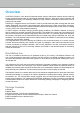
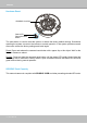
VIVOTEK Overview VIVOTEK’s FD8361L is the latest professional-series outdoor fixed dome network camera featuring superb megapixel image quality and exceptional bandwidth efficiency.
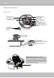
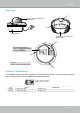
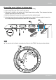
VIVOTEK Physical Description Inner View IR LEDs (18 units, distance 20m) Light Sensor Rotation Adjustment Screw Tilt Adjustment Screw Pan Adjustment Screw NTSC/PAL Video Output Switch Vari-focal Lens (f= 3~9 mm) SD/SDHC Card Slot Status LED Recessed Reset Button Focus Controller Zoom Controller BNC Video Output General I/O Terminal Block AC24V AC24V Ethernet 10/100 RJ45 Plug Ground Operating environment: -20° ~ 50°C When the temparature inside the Network Camera reaches over 50°C, the fan will oper
VIVOTEK AC24V AC24V Outer View c IP66-rated Vandal-proof Dome Cover AC24V AC24V b a Camera Base IP66-rated Vandal-proof Bottom Base c Record the MAC address under the camera base before installing the camera� Network Camera Model No: FD8361 RoHS V I MAC:0002D1083236 CLASS A a This device complies with part 15 of the FCC rules.
VIVOTEK Hardware Reset SD/SDHC Card Slot Status LED Recessed Reset Button The reset button is used to reset the system or restore the factory default settings� Sometimes resetting the system can return the camera to normal operation� If the system problems remain after reset, restore the factory settings and install again� Reset: Press and release the recessed reset button with a paper clip or thin object� Wait for the Network Camera to reboot� Restore: Press and hold the recessed reset button until the
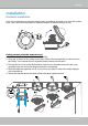
VIVOTEK Installation Hardware Installation First, use a screwdriver to loose the three screws and detach the dome cover from the camera base� Then, follow the steps below to install the camera to either a ceiling or a wall� AC24V AC24V Ceiling mount (with the bottom base) 1� Attach the supplied alignment sticker to the ceiling� 2� Using the 10 circles on the sticker, drill at least 2 pilot holes symmetrically on each side into the ceiling� Then hammer the four supplied plastic anchors into the holes� 3�
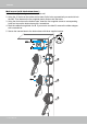
VIVOTEK Wall mount (with the bottom base) 1� Attach the supplied alignment sticker to the wall� 2� Using the 10 circles on the sticker, drill at least 2 pilot holes symmetrically on each side into the wall� Then hammer the four supplied plastic anchors into the holes� 3� Using the four holes on the bottom base, insert the four supplied screws to corresponding holes and secure the bottom base with a screwdriver� 4� Feed the cables through hole A or B� If you want to use hole B, remove the rubber stopper wit
VIVOTEK Drop-ceiling mount (without the bottom base) 1� Attach the supplied ceiling hole template sticker to the ceiling� 2� Open a hole along the inner circle of the sticker� 3� Using the 3 circles on the sticker, drill 3 pilot holes into the ceiling� Then hammer the three supplied plastic anchors into the holes� 4� Mount the Network Camera to the ceiling and feed the cables through� 5� Using the three holes on the side of the camera base, insert the three supplied screws into the corresponding holes and
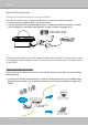
VIVOTEK Network Deployment Setting up the Network Camera over the Internet This section explains how to configure the Network Camera to an Internet connection� 1� Connect the power cable to the AC 24V terminal block� 2. Use the supplied RJ45 female/female coupler to connect the Network Camera to a switch.
VIVOTEK 2� In this case, if the Local Area Network (LAN) IP address of your Network Camera is 192�168�0�3, please forward the following ports for the Network Camera on the router� ■ HTTP port ■ RTSP port ■ RTP port for video ■ RTCP port for video If you have changed the port numbers on the Network page, please open the ports accordingly on your router� For information on how to forward ports on the router, please refer to your router’s user’s manual� 3� Find out the public IP address of your router provide
VIVOTEK Set up the Network Camera through Power over Ethernet (PoE) When using a PoE-enabled switch The Network Camera is PoE-compliant, allowing transmission of power and data via a single Ethernet cable� Follow the below illustration to connect the Network Camera to a PoE-enabled switch via Ethernet cable� AC24V AC24V power + data transmission POWER COLLISION 1 2 3 4 5 LINK RECEIVE PARTITION PoE Switch When using a non-PoE switch If your switch/router does not support PoE, use a PoE power inj
VIVOTEK Software Installation Installation Wizard 2 (IW2), free-bundled software included on the product CD, helps you set up your Network Camera on the LAN� 1� Install IW2 under the Software Utility directory from the software CD� Double click the IW2 shortcut on your desktop to launch the program� 2� The program will conduct an analysis of your network environment� After your network environment is analyzed, please click Next to continue the program� 3� The program will search for all VIVOTEK network de
VIVOTEK Ready to Use 1� Access the Network Camera on the LAN� 2� Retrieve live video through a web browser or recording software� Adjusting the Lens Based on the live image retrieved from the camera, adjust the camera lens by doing the following: To adjust the viewing angle -- 3-axis mechanism design 1� Loosen the pan adjustment screw and then turn the lens module left and right� Upon completion, tighten the screw� 2� Loosen the tilt adjustment screws on both side of the camera and then turn the lens modu
VIVOTEK To adjust the zoom factor and focus range 1� Loosen the zoom controller to adjust the zoom factor� Upon completion, tighten the zoom controller� 2� Loosen the focus controller to adjust the focus range� Upon completion, tighten the focus controller� 1 2 3 4 AV Out Audio In Loosen Ext PAL 1 2 ON Int. NTSC W N 8 Tighten T DO NOT over rotate the lens� Doing so will damage the camera lens module Completion 1. Rotate the black cover inside the dome cover to fit the lens shooting direction.
VIVOTEK Accessing the Network Camera This chapter explains how to access the Network Camera through web browsers, RTSP players, 3GPP-compatible mobile devices, and VIVOTEK recording software� Using Web Browsers Use Installation Wizard 2 (IW2) to access to the Network Cameras on the LAN� If your network environment is not a LAN, follow these steps to access the Network Camera: 1� Launch your web browser (ex� Microsoft® Internet Explorer, Mozilla Firefox, or Netscape)� 2.
VIVOTEK ► By default, the Network Camera is not password-protected. To prevent unauthorized access, it is highly recommended to set a password for the Network Camera� For more information about how to enable password protection, please refer to Security on page 30� ► If you see a dialog box indicating that your security settings prohibit running ActiveX ® Controls, please enable the ActiveX ® Controls for your browser� 1� Choose Tools > Internet Options > Security > Custom Level� 2.
VIVOTEK Using RTSP Players To view the MPEG-4 streaming media using RTSP players, you can use one of the following players that support RTSP streaming� Quick Time Player Real Player VLC media player 1� Launch the RTSP player� mpegable Player 2� Choose File > Open URL� A URL dialog box will pop up� 3� The address format is rtsp://:/ As most ISPs and players only allow RTSP streaming through port number 554, please set the RTS
VIVOTEK Using 3GPP-compatible Mobile Devices To view the streaming media through 3GPP-compatible mobile devices, make sure the Network Camera can be accessed over the Internet� For more information on how to set up the Network Camera over the Internet, please refer to Setup the Network Camera over the Internet on page 10� To utilize this feature, please check the following settings on your Network Camera: 1� Because most players on 3GPP mobile phones do not support RTSP authentication, make sure the authen
VIVOTEK Using VIVOTEK Recording Software The product software CD also contains recording software, allowing simultaneous monitoring and video recording for multiple Network Cameras� Please install the recording software; then launch the program to add the Network Camera to the Channel list� For detailed information about how to use the recording software, please refer to the user’s manual of the software or download it from http://www�vivotek�com� 20 - User's Manual
VIVOTEK Main Page This chapter explains the layout of the main page� It is composed of the following sections: VIVOTEK INC� Logo, Host Name, Camera Control Area, Configuration Area, Menu, and Live Video Window� VIVOTEK INC. Logo Host Name Camera Control Area Configuration Area Live View Window VIVOTEK INC. Logo Click this logo to visit the VIVOTEK website� Host Name The host name can be customized to fit your needs.
VIVOTEK Configuration Area Client Settings: Click this button to access the client setting page� For more information, please refer to Client Settings on page 25� Configuration: Click this button to access the configuration page of the Network Camera.
VIVOTEK Pause: Pause the transmission of the streaming media� The button becomes the after clicking the Pause button� Stop: Stop the transmission of the streaming media� Click the transmission� Resume button Resume button to continue Start MP4 Recording Recording: Click this button to record video clips in MP4 file format to your computer� Stop MP4 Recording button to end recording� When you exit the web browser, video Press the recording stops accordingly.
VIVOTEK Start MP4 Recording Recording: Click this button to record video clips in MP4 file format to your computer� Stop MP4 Recording button to end recording� When you exit the web browser, video Press the recording stops accordingly.
VIVOTEK Client Settings This chapter explains how to select the stream transmission mode and saving options on the local computer� When completed with the settings on this page, click Save on the page bottom to enable the settings� H.264 / MPEG-4 Protocol Options H.
VIVOTEK MP4 Saving Options Users can record live video as they are watching it by clicking page. Here, you can specify the storage destination and file name. Start MP4 Recording on the main Folder: Specify a storage destination for the recorded video files. File name prefix: Enter the text that will be appended to the front of the video file name. Add date and time suffix to the file name: Select this option to append the date and time to the end of the file name.
VIVOTEK Configuration Click Configuration on the main page to enter the camera setting pages� Note that only Administrators can access the configuration page.
VIVOTEK Advanced Mode Configuration List Click to switch to Basic Mode Firmware Version Each function on the configuration list will be explained in the following sections. Those functions that are displayed only in Advanced Mode are marked with Advanced Mode � If you want to set up advanced functions, please click [Advanced Mode] on the bottom of the configuration list to quickly switch over.
VIVOTEK System Time Keep current date and time: Select this option to preserve the current date and time of the Network Camera� The Network Camera’s internal real-time clock maintains the date and time even when the power of the system is turned off� Synchronize with computer time: Select this option to synchronize the date and time of the Network Camera with the local computer� The read-only date and time of the PC is displayed as updated� Manual: The administrator can enter the date and time manually� N
VIVOTEK Security This section explains how to enable password protection and create multiple accounts� Root Password The administrator account name is “root”, which is permanent and can not be deleted� If you want to add more accounts in the Manage User column, please apply the password for the “root” account first.
VIVOTEK HTTPS (Hypertext Transfer Protocol over SSL) Advanced Mode This section explains how to enable authentication and encrypted communication over SSL (Secure Socket Layer)� It helps protect streaming data transmission over the Internet on higher security level� Enable HTTPS Check this item to enable HTTPS communication, then select a connection option: "HTTP & HTTPS" or "HTTPS only".
VIVOTEK 4. The Certificate Information will automatically be displayed in the third column as shown below. You can click Property to view detailed information about the certificate. 5� Click Home to return to the main page� Change the address from “http://” to “https://“ in the address bar and press Enter on your keyboard� Some Security Alert dialogs will pop up� Click OK or Yes to enable HTTPS� https:// https://192.168.5.151/index.
VIVOTEK Create self-signed certificate manually 1� Select this option� 2� Click Create to open the Create Certificate page, then click Save to generate the certificate. 3. The Certificate Information will automatically be displayed in the third column as shown below. You can click Property to see detailed information about the certificate.
VIVOTEK 3� If you see the following Information bar, click OK and click on the Information bar at the top of the page to allow pop-ups� 4. The pop-up window shows an example of a certificate request.
VIVOTEK 5� Look for a trusted certificate authority that issues digital certificates� Enroll the Network Camera� Wait for the certificate authority to issue a SSL certificate; click Browse... to search for the issued certificate, then click Upload in the second column.
VIVOTEK SNMP (Simple Network Management Protocol) Advanced Mode This section explains how to use the SNMP on the network camera� The Simple Network Management Protocol is an application layer protocol that facilitates the exchange of management information between network devices� It helps network administrators to remotely manage network devices and find, solve network problems with ease.
VIVOTEK Network This section explains how to configure a wired network connection for the Network Camera.
VIVOTEK Primary DNS: The primary domain name server that translates hostnames into IP addresses� Secondary DNS: Secondary domain name server that backups the Primary DNS� Primary WINS server: The primary WINS server that maintains the database of computer name and IP address� Secondary WINS server: The secondary WINS server that maintains the database of computer name and IP address� Enable UPnP presentation: Select this option to enable UPnPTM presentation for your Network Camera so that whenever a Networ
VIVOTEK NOTE ► If the default ports are already used by other devices connected to the same router, the Network Camera will select other ports for the Network Camera� ► If UPnP TM is not supported by your router, you will see the following message: Error: Router does not support UPnP port forwarding.
VIVOTEK 4� In the Networking Services dialog box, select Universal Plug and Play and click OK� 5� Click Next in the following window� 6� Click Finish� UPnP TM is enabled� ► How does UPnP TM work? UPnP TM networking technology provides automatic IP configuration and dynamic discovery of devices added to a network. Services and capabilities offered by networked devices, such as printing and file sharing, are available among each other without the need for cumbersome network configuration.
VIVOTEK Enable IPv6 Select this option and click Save to enable IPv6 settings� Please note that this only works if your network environment and hardware equipment support IPv6� The browser should be Microsoft® Internet Explorer 6�5, Mozilla Firefox 3�0 or above� When IPv6 is enabled, by default, the network camera will listen to router advertisements and be assigned with a link-local IPv6 address accordingly� IPv6 Information: Click this button to obtain the IPv6 information as shown below� If your IPv6
VIVOTEK Please follow the steps below to link to an IPv6 address: 1� Open your web browser� 2� Enter the link-global or link-local IPv6 address in the address bar of your web browser� 3� The format should be: http://[2001:0c08:2500:0002:0202:d1ff:fe04:65f4]/ IPv6 address 4� Press Enter on the keyboard or click Refresh button to refresh the webpage� For example: NOTE ► If you have a Secondary HTTP port (the default value is 8080), you can also link to the webpage in the following address format: (Please r
VIVOTEK IEEE 802�1x Advanced Mode Enable this function if your network environment uses IEEE 802�1x, which is a port-based network access control� The network devices, intermediary switch/access point/hub, and RADIUS server must support and enable 802�1x settings� The 802�1x standard is designed to enhance the security of local area networks, which provides authentication to network devices (clients) attached to a network port (wired or wireless).
VIVOTEK 3� When all settings are complete, move the Network Camera to the protected LAN by connecting it to an 802�1x enabled switch� The devices will then start the authentication automatically� NOTE ► The authentication process for 802�1x: 1� The Certificate Authority (CA) provides the required signed certificates to the Network Camera (the supplicant) and the RADIUS Server (the authentication server)� 2� A Network Camera requests access to the protected LAN using 802.
VIVOTEK QoS (Quality of Service) Advanced Mode Quality of Service refers to a resource reservation control mechanism, which guarantees a certain quality to different services on the network� Quality of service guarantees are important if the network capacity is insufficient, especially for real-time streaming multimedia applications.
VIVOTEK QoS/DSCP (the DiffServ model) DSCP-ECN defines QoS at Layer 3 (Network Layer)� The Differentiated Services (DiffServ) model is based on packet marking and router queuing disciplines.
VIVOTEK HTTP Advanced Mode To utilize HTTP authentication, make sure that your have set a password for the Network Camera first; please refer to Security on page 30 for details� Authentication: Depending on your network security requirements, the Network Camera provides two types of security settings for an HTTP transaction: basic and digest� If basic authentication is selected, the password is sent in plain text format and there can be potential risks of being intercepted� If digest authentication is sel
VIVOTEK URL command -- http://:/ For example, when the Access name for stream 2 is set to video2�mjpg: 1� Launch Mozilla Firefox or Netscape� 2� Type the above URL command in the address bar� Press Enter� 3. The JPEG images will be displayed in your web browser. http://192.168.5.151/video2.
VIVOTEK RTSP Streaming To utilize RTSP streaming authentication, make sure that you have set a password for the Network Camera first; please refer to Security on page 30 for details� Authentication: Depending on your network security requirements, the Network Camera provides three types of security settings for streaming via RTSP protocol: disable, basic, and digest� If basic authentication is selected, the password is sent in plain text format, but there can be potential risks of it being intercepted� I
VIVOTEK RTSP port /RTP port for video/ RTCP port for video ■ RTSP (Real-Time Streaming Protocol) controls the delivery of streaming media. By default, the port number is set to 554� ■ The RTP (Real-time Transport Protocol) is used to deliver video data to the clients. By default, the RTP port for video is set to 5556� ■ The RTCP (Real-time Transport Control Protocol) allows the Network Camera to transmit the data by monitoring the Internet traffic volume. By default, the RTCP port for video is set to 5557.
VIVOTEK DDNS This section explains how to configure the dynamic domain name service for the Network Camera� DDNS is a service that allows your Network Camera, especially when assigned with a dynamic IP address, to have a fixed host and domain name. DDNS: Dynamic domain name service Enable DDNS: Select this option to enable the DDNS setting� Provider: Select a DDNS provider from the provider drop-down list� VIVOTEK offers Safe100.
VIVOTEK [Register] Successfully Your account information has been mailed to registered e-mail address 4� Select Enable DDNS and click Save to enable the setting� ■ CustomSafe100 VIVOTEK offers documents to establish a CustomSafe100 DDNS server for distributors and system integrators� You can use CustomSafe100 to register a dynamic domain name if your distributor or system integrators offer such services� 1� In the DDNS column, select CustomSafe100 from the drop-down list� 2.
VIVOTEK Access List Advanced Mode This section explains how to control access permission by verifying the client PC’s IP address� General Settings Maximum number of concurrent streaming connection(s) limited to: Simultaneous live viewing for 1~10 clients (including stream 1 ~ stream 5)� The default value is 10� If you modify the value and click Save, all current connections will be disconnected and automatically attempt to re-link (IE Explore or Quick Time Player)� View Information: Click this button to
VIVOTEK ■ Refresh: Click this button to refresh all current connections. ■ Add to deny list: You can select entries from the Connection Status list and add them to the Deny List to deny access� Please note that those checked connections will only be disconnected temporarily and will automatically try to re-link again (IE Explore or Quick Time Player)� If you want to enable the denied list, please check Enable access list filtering and click Save in the first column.
VIVOTEK Network: This rule allows the user to assign a network address and corresponding subnet mask to the Allow/Deny List� For example: IP address 192�168�2�x will be blocked� Range: This rule allows the user to assign a range of IP addresses to the Allow/Deny List� Note: This rule is only applied to IPv4� For example: Administrator IP address Always allow the IP address to access this device: You can check this item and add the Administrator’s IP address in this field to make sure the Administrator c
VIVOTEK Video This section explains how to configure the video settings of the Network Camera.
VIVOTEK Overlay title and time stamp on video: Select this option to place the video title and time on the video streams� Note that when the frame size is set to 176 x 144 as shown in the picture below, only the time will be stamped on the video streams� 2010/10/30 13:44:17 13:44:17 2010/10/30 Options of Video Advanced Mode There are three options for you to choose: Video quality first, Video frame rate first, and Cropping mode� Select either one mode according to your needs� ■ Video quality first: Sele
VIVOTEK 2010/10/30 13:44:17 White balance: Adjust the value for the best color temperature� ■ Auto The Network Camera automatically adjusts the color temperature of the light in response to different light sources� The white balance setting defaults to Auto and works well in most situations� ■ Keep current value Follow the steps below to manually set the white balance to compensate for the ambient lighting conditions� 1� Set the White balance to Auto and click Save� 2� Place a sheet of white paper in fron
VIVOTEK Privacy Mask Advanced Mode Click Privacy Mask to open the settings page� On this page, you can block out sensitive zones to address privacy concerns� 2010/10/31 13:44:17 2010/10/31 13:44:17 ■ To set the privacy mask windows, follow the steps below: 1� Click New to add a new window� 2� Use the mouse to size and drag-drop the window, which is recommended to be at least twice the size of the object (height and width) you want to cover� 3� Enter a Window Name and click Save to enable the setting� 4�
VIVOTEK Sensor Settings Advanced Mode Click Sensor Settings to open the Sensor Settings page� On this page, you can set the maximum exposure time, exposure level, and AGC (Auto Gain Control) settings� You can configure two sets of sensor settings: one for normal situations, the other for special situations, such as day/night/schedule mode� 2010/10/30 13:44:17 Sensor Setting 1: For normal situations Sensor Setting 2: For special situations Exposure ■ Maximum Exposure Time: Select a proper maximum exposure
VIVOTEK If you want to configure another sensor setting for day/night/schedule mode, please click Profile to open the Sensor Settings Profile Settings page as shown below.
VIVOTEK Viewing Window Advanced Mode Click Viewing Window to open the Viewing Window Settings page� This Network Camera supports multiple streams with frame size ranging from 176 x 144 to 1600 x 1200� The definition of multiple streams: ■ Stream 1: Users can define the "Region of Interest" (viewing region) and the "Output Frame Rate" (size of the live view window)� ■ Stream 2: Users can define the "Region of Interest" (viewing region) and the "Output Frame Rate" (size of the live view window)� ■ Stream 3
VIVOTEK Click Viewing Window to open the viewing region settings page� On this page, you can set the Region of Interest and the Output Frame Size for stream 1 ~ 3� Please follow the steps below to set up those settings for a stream: 1� Select a stream which you want to set up the viewing region� If you want to stream out the video to a mobile device, please select stream 3� 2� Select a Region of Interest from the drop-down list.
VIVOTEK Cropping Setting Advanced Mode Click Cropping Setting to open the Cropping Settings page� Please follow the steps below to set up cropping mode for mutiple streams: 1� Click Cropping Setting to open the window as shown below� 2� Select a Captured area from the drop-down list.
VIVOTEK Video Quality Settings Advanced Mode Click the stream item to display the detailed information� The maximum frame size will follow your settings in above sections� fixed This Network Camera offers real-time H.264, MPEG-4 and MJEPG compression standards (Triple Codec) for real-time viewing� If H.
VIVOTEK ■ Intra frame period Determine how often to plant an I frame� The shorter the duration, the more likely you will get better video quality, but at the cost of higher network bandwidth consumption� Select the intra frame period from the following durations: 1/4 second, 1/2 second, 1 second, 2 seconds, 3 seconds, and 4 seconds� ■ Video quality A complex scene generally produces a larger file size, meaning that higher bandwidth will be needed for data transmission� Therefore, if Constant bit rate is se
VIVOTEK Day/Night Settings Switch to B/W in night mode Select this to enable the Network Camera to automatically switch to B/W during night mode� IR cut filter With a removable IR-cut filter, this Network Camera can automatically remove the filter to let IR light into the sensor during low light conditions� ■ Auto mode The Network Camera automatically removes the filter by judging the level of ambient light.
VIVOTEK Motion Detection This section explains how to configure the Network Camera to enable motion detection. A total of three motion detection windows can be configured.
VIVOTEK A green bar indicates that even though motions have been detected, the event has not been triggered because the image variations still fall under the defined threshold. Percentage = 30% If you want to configure other motion detection settings for day/night/schedule mode, please click Profile to open the Motion Detection Profile Settings page as shown below� A total of three motion detection windows can be configured on this page as well.
VIVOTEK NOTE ► How does motion detection work? A C B D There are two motion detection parameters: Sensitivity and Percentage� In the illustration above, frame A and frame B are two sequential images� Pixel differences between the two frames are detected and highlighted in gray (frame C) and will be compared with the sensitivity setting� Sensitivity is a value that expresses the sensitivity to moving objects� Higher sensitivity settings are expected to detect slight movements while smaller sensitivity s
VIVOTEK Camera Tampering Detection This section explains how to set up camera tamper detection� With tamper detection, the camera is capable of detecting incidents such as redirection, blocking or defocusing, or even spray paint� Please follow the steps below to set up the camera tamper detection function: 1� Check Enable camera tampering detection� 2� Enter the tamper trigger duration� (10 sec� ~ 10 min�) The tamper alarm will be triggered only when the tampering factor (the difference between current fr
VIVOTEK Camera Control This section explains how to control the Network Camera’s e-Pan/Tilt/Zoom operation� It allows users to quickly move the focus to a target area for close-up viewing without moving the camera physically� 2010/10/31 13:44:17 Select Stream: Select one of the stream 1~3 to set up the e-PTZ control� Please note that each stream can be set up with its own e-preset positions and e-patrol settings� For detailed information about how to set up E-Preset Positions and E-Patrol Settings, please
VIVOTEK E-Preset Positions A total of 20 preset positions can be configured. You can select preset positions for the camera to patrol.
VIVOTEK E-Patrol Settings You can select some preset positions for the Network Camera to patrol� Please follow the steps below to set up a patrol schedule: 1� Click a preset location on the list and click Select� 2� The selected preset location will be displayed on the Source list� 3� Set the Dwelling time for the preset location during auto patrol� You can also manually enter a value in the blank and click Update� 4� Repeat step 1 and 3 to select additional preset locations� 5� If you want to delete a se
VIVOTEK Home page 2009/12/05 13:44:17 x1.
VIVOTEK Homepage Layout Advanced Mode This section explains how to set up your own customized homepage layout� Preview This column shows the settings of your hompage layout� You can manually select the background and font colors in Theme Options (the third column on this page)� The settings will be displayed automatically in this Preview field.
VIVOTEK Theme Options Here you can change the color of your homepage layout� There are three types of preset patterns for you to choose from� The new layout will simultaneously appear in the Preview filed.
VIVOTEK ■ Follow the steps below to set up the customed homepage: 1� Click Custom on the left column� 2. Click the field where you want to change the color on the right column. Color Selector Custom Pattern 3� The palette window will pop up as shown below� 2 3 1 4 4� Drag the slider bar and click on the left square to select a desired color� 5.
VIVOTEK Application Advanced Mode This section explains how to configure the Network Camera to responds to particular situations (event)� A typical application is that when a motion is detected, the Network Camera sends buffered images to an FTP server or e-mail address as notifications. In the illustration on the right, an event can be Action triggered by many sources, such as motion detection Event Trigger or external digital input devices� When an event is ex.
VIVOTEK Event Settings In the Event Settings column, click Add to open the Event Settings page� On this page, you can arrange three elements -- Trigger, Schedule, and Action to set an event� A total of 3 event settings can be configured. Event name: Enter a name for the event setting� Enable this event: Select this option to enable the event setting� Priority: Select the relative importance of this event (High, Normal, or Low)� Events with a higher priority setting will be executed first.
VIVOTEK An event is an action initiated by a user-defined trigger source; it is the causal arrangement of the following three elements: Trigger, Event Schedule, and Action� Trigger This is the cause or stimulus which defines when to trigger the Network Camera.
VIVOTEK ■ Camera tampering detection This option allows the Network Camera to trigger when the camera detects that is is being tampered with� To enable this function, you need to configure the Tampering Detection option first. Please refer to page 71 for detailed information� Event Schedule Specify the period for the event� ■ Select the days of the week. ■ Select the recording schedule in 24-hr time format. Action Define the actions to be performed by the Network Camera when a trigger is activated.
VIVOTEK To set an event with recorded video or snapshots, it is necessary to configure the server and media settings so that the Network Camera will know what action to take (such as which server to send the media files to) when a trigger is activated� ■ Add Server / Add Media Click Add Server to configure Server Settings� For more information, please refer to Server Settings on page 85� Click Add Media to configure Media Settings� For more information, please refer to Media Settings on page 88� Here is
VIVOTEK When completed, click Save to enable the settings and click Close to exit Event Settings page� The new event settings / server settings / media settings will appear in the event drop-down list on the Application page� Here is an example of the Application page with an event setting: When the Event Status is ON, once an event is triggered by motion detection, the Network Camera will automatically send snapshots via e-mail� If you want to stop the event trigger, you can click ON to turn it to OFF st
VIVOTEK Server Settings Click Add Server on Event Settings page to open the Server Setting page� On this page, you can specify where the notification messages are sent when a trigger is activated. A total of 5 server settings can be configured. Server name: Enter a name for the server setting� Server Type There are four choices of server types available: Email, FTP, HTTP, and Network storage� Select the item to display the detailed configuration options. You can configure either one or all of them.
VIVOTEK FTP: Select to send the media files to an FTP server when a trigger is activated. ■ Server address: Enter the domain name or IP address of the FTP server. ■ Server port By default, the FTP server port is set to 21� It can also be assigned to another port number between 1025 and 65535� ■ User name: Enter the login name of the FTP account. ■ Password: Enter the password of the FTP account. ■ FTP folder name Enter the folder where the media file will be placed.
VIVOTEK HTTP: Select to send the media files to an HTTP server when a trigger is activated. ■ URL: Enter the URL of the HTTP server. ■ User name: Enter the user name if necessary. ■ Password: Enter the password if necessary. To verify if the HTTP settings are correctly configured, click Test� The result will be shown in a pop-up window as below. If successful, you will receive a test.txt file on the HTTP server.
VIVOTEK Media Settings Click Add Media on the Event Settings page to open the Media Settings page� On this page, you can specify the type of media that will be sent when a trigger is activated� A total of 5 media settings can be configured. Media name: Enter a name for the media setting� Media Type There are three choices of media types available: Snapshot, Video Clip, and System log� Select the item to display the detailed configuration options. You can configure either one or all of them.
VIVOTEK Video clip: Select to send video clips when a trigger is activated� ■ Source: The source of video clip, which will be identical to the time shift caching stream.
VIVOTEK You can continue to select a server and media type for the event� Please go back to page 66 for detailed information� ■ SD Test: Click to test your SD card� The system will display a message indicating success or failure� If you want to use your SD card for local storage, please format it before use� Please refer to page 92 for detailed information� ■ Create folders by date, time, and hour automatically: If you check this item, the system will generate folders automatically by date� ■ View: Click
VIVOTEK The following is an example of a file destination with video clips: The format is: YYYYMMDD Click to open the directory 20091120 20091121 20091122 Click to delete all recorded data Click to delete selected items Click 20091120 to open the directory: The format is: HH (24r) Click to open the file list for that hour Video Clip_58.mp4 2009/11/20 Video Clip_59.
VIVOTEK Recording Advanced Mode This section explains how to configure the recording settings for the Network Camera. Recording Settings Insert your SD card and click here to test NOTE ► Before setting up this page, please set up the Network Storage on the Server Settings page first. ► Please remember to format your SD card when using for the first time.
VIVOTEK If successful, you will receive a test.txt file on the network storage server. 3� Enter a server name� 4� Click Save to complete the settings and click Close to exit the page� Recording Settings Click Add to open the recording setting page� In this page, you can define the recording source, recording schedule, and recording capacity. A total of 2 recording settings can be configured.
VIVOTEK Source: Select the recording source (stream 1 ~ 4)� Trigger: Select a trigger source� ■ Schedule: The server will start to record files on the local storage or network storage (NAS). ■ Network fail: Since network fail, the server will start to record files on the local storage (SD card). Recording Schedule: Specify the recording duration� ■ Select the days of the week. ■ Select the recording start and end times in 24-hr time format.
VIVOTEK Local Storage Advanced Mode This section explains how to manage the local storage on the Network Camera� Here you can view SD card status, search for recorded files to playback, download, etc. no SD card SD Card Management SD card status: This column shows the status and reserved space of your SD card� Please remember to format the SD card when using for the first time.
VIVOTEK SD card control ■ Enable cyclic storage: Check this item if you want to enable cyclic recording� When the maximum capacity is reached, the oldest file will be overwritten by the latest one. ■ Enable automatic disk cleanup: Check this item and enter the number of days you wish to retain a file. For example, if you enter “7 days”, the recorded files will be stored on the SD card for 7 days.
VIVOTEK Search Results The following is an example of search results� There are four columns: Trigger time, Media type, Trigger type, and Locked� Click to sort the search results in either direction� Enter a key word to filter the Numbers of entries displayed on one page search results Highlight an item Click to switch pages View: Click on a search result which will highlight the selected item in purple as shown above� Click the View button and a media window will pop up to play back the selected file.
VIVOTEK Download: Click on a search result to highlight the selected item in purple as shown above� Then click the Download button and a file download window will pop up for you to save the file. JPEGs to AVI: This functions only applies to “JPEG“ format files such as snapshots. You can select several snapshots from the list, then click this button. Those snapshots will be converted into an AVI file.
VIVOTEK System Log Advanced Mode This section explains how to configure the Network Camera to send the system log to the remote server as backup� Remote Log You can configure the Network Camera to send the system log file to a remote server as a log backup.
VIVOTEK View Parameters Advanced Mode The View Parameters page lists the entire system’s parameters in alphabetical order� If you need technical assistance, please provide the information listed on this page� 100 - User's Manual
VIVOTEK Maintenance This chapter explains how to restore the Network Camera to factory default, upgrade firmware version, etc� Reboot This feature allows you to reboot the Network Camera, which takes about one minute to complete� When completed, the live video page will be displayed in your browser� The following message will be displayed during the reboot process� If the connection fails after rebooting, manually enter the IP address of the Network Camera in the address field to resume the connection.
VIVOTEK Export / Upload Files Advanced Mode This feature allows you to Export / Upload daylight saving time rules, custom language files, and setting backup files. Export daylight saving time configuration file: Click to set the start and end time of DST� Follow the steps below to export: 1. In the Export files column, click Export to export the daylight saving time configuration file from the Network Camera� 2. A file download dialog will pop up as shown below.
VIVOTEK Upload daylight saving time rule: Click Browse… and specify the XML file to upload. If the incorrect date and time are assigned, you will see the following warning message when uploading the file to the Network Camera. The following message is displayed when attempting to upload an incorrect file format.
VIVOTEK The following message is displayed when the upgrade has succeeded� Reboot system now!! This connection will close. The following message is displayed when you have selected an incorrect firmware file. Starting firmware upgrade... Do not power down the server during the upgrade. The server will restart automatically after the upgrade is completed. This will take about 1 - 5 minutes.
VIVOTEK Appendix URL Commands for the Network Camera Overview For some customers who already have their own web site or web control application, the Network Camera/Video Server can be easily integrated through URL syntax� This section specifies the external HTTP-based application programming interface� The HTTP-based camera interface provides the functionality to request a single image, control camera functions (PTZ, output relay etc�), and get and set internal parameter values� The image and CGI-requests
VIVOTEK General CGI URL Syntax and Parameters CGI parameters are written in lower-case and as one word without any underscores or other separators. When the CGI request includes internal camera parameters, these parameters must be written exactly as they are named in the camera or video server. The CGIs are organized in functionally-related directories under the cgi-bin directory. The file extension .cgi is required. Syntax: http:///cgi-bin/[/...]/.
VIVOTEK http:///cgi-bin/operator/getparam.cgi?[] [&…] http:///cgi-bin/admin/getparam.cgi?[] [&…] Where the should be [_] or [.]. If you do not specify any parameters, all the parameters on the server will be returned. If you specify only , the parameters of the related group will be returned. client When querying parameter values, the current parameter values are returned.
VIVOTEK Method: GET/POST Syntax: http:///cgi-bin/anonymous/setparam.cgi? = [&=…][&update=][&return=] http:///cgi-bin/viewer/setparam.cgi? = [&=…][&update=] [&return=] http:///cgi-bin/operator/setparam.cgi? = [&=…][&update=] [&return=] http:///cgi-bin/admin/setparam.
VIVOTEK Example: Set the IP address of server to 192.168.0.123: Request: http://myserver/cgi-bin/admin/setparam.cgi?network_ipaddress=192.168.0.123 Response: HTTP/1.0 200 OK\r\n Content-Type: text/html\r\n Context-Length: 33\r\n \r\n network.ipaddress=192.168.0.123\r\n Available parameters on the server Valid values: VALID VALUES DESCRIPTION string[] Text strings shorter than ‘n’ characters. The characters “,’, <,>,& are invalid.
VIVOTEK text SQLite data type. The value is a text string, stored using the database encoding (UTF-8, UTF-16BE or UTF-16-LE). coordinate x, y coordinate (eg. 0,0) window size window width and height (eg. 800x600) NOTE: The camera should not be restarted when parameters are changed. Group: system NAME VALUE SECURITY DESCRIPTION (get/set) hostname string[40] 1/6 Host name of server (Network Camera, Wireless Network Camera, Video Server, Wireless Video Server).
VIVOTEK Time, Mexico City, Saskatchewan -200: GMT-05:00 Eastern Time, New York, Toronto -201: GMT-05:00 Bogota, Lima, Quito, Indiana -180: GMT-04:30 Caracas -160: GMT-04:00 Atlantic Time, Canada, La Paz, Santiago -140: GMT-03:30 Newfoundland -120: GMT-03:00 Brasilia, Buenos Aires, Georgetown, Greenland -80: GMT-02:00 Mid-Atlantic -40: GMT-01:00 Azores, Cape_Verde_IS.
VIVOTEK 360: GMT 09:00 Osaka, Sapporo, Tokyo, Seoul, Yakutsk 380: GMT 09:30 Adelaide, Darwin 400: GMT 10:00 Brisbane, Canberra, Melbourne, Sydney, Guam, Vladivostok 440: GMT 11:00 Magadan, Solomon Is., New Caledonia 480: GMT 12:00 Aucklan, Wellington, Fiji, Kamchatka, Marshall Is. 520: GMT 13:00 Nuku'Alofa Daylight_enable 6/6 Enable automatic daylight saving time in time zone. daylight_dstactual 1~4 6/7 mode Check if current time is under daylight saving time.
VIVOTEK This command can cooperate with other “restoreexceptXYZ” commands. When cooperating with others, the system parameters will be restored to default values except for a union of combined results. restoreexceptlang 0, 7/6 Restore the system parameters to default values except the custom language file the user has uploaded. This command can cooperate with other “restoreexceptXYZ” commands.
VIVOTEK onlinenum_httppush integer 6/7 Current number of HTTP push server connections. eth_i0 1/99 Get network information from emac_link.
VIVOTEK Subgroup of network: ieee8021x NAME VALUE SECURITY DESCRIPTION (get/set) enable 6/6 Enable/disable IEEE 802.1x eapmethod eap-peap, 6/6 Selected EAP method eap-tls identity_peap String[64] 6/6 PEAP identity identity_tls String[64] 6/6 TLS identity password String[254] 6/6 Password for TLS privatekeypassword String[254] 6/6 Password for PEAP ca_exist 6/6 CA installed flag ca_time 6/7 CA installed time.
VIVOTEK Subgroup of network: ipv6 NAME VALUE SECURITY DESCRIPTION (get/set) enable 6/6 Enable IPv6. addonipaddress 6/6 IPv6 IP address. addonprefixlen 0~128 6/6 IPv6 prefix length. addonrouter 6/6 IPv6 router address. addondns 6/6 IPv6 DNS address. allowoptional 6/6 Allow manually setup of IP address setting.
VIVOTEK Subgroup of network: https NAME VALUE SECURITY DESCRIPTION (get/set) port 443, 1025 ~ 65535 6/6 HTTPS port. Subgroup of network: rtsp NAME VALUE SECURITY DESCRIPTION (get/set) port 554, 1025 ~ 65535 1/6 RTSP port. (capability.protocol.rtsp=1) anonymousviewing 1/6 Enable anoymous streaming viewing. authmode disable, 1/6 RTSP authentication mode. basic, (capability.protocol.rtsp=1) digest s0_accessname string[32] 1/6 RTSP access name for stream1. (capability.
VIVOTEK Subgroup of network_rtsp_s<0~(n-1)>: multicast, n is stream count (capability.protocol.rtp.multicast=1) NAME VALUE SECURITY DESCRIPTION (get/set) alwaysmulticast 4/4 Enable always multicast. ipaddress 4/4 Multicast IP address. videoport 1025 ~ 65535 4/4 Multicast video port. audioport 1025 ~ 65535 4/4 Multicast audio port. ttl 1 ~ 255 4/4 Multicast time to live value.
VIVOTEK 0 => allow 1 => deny ipv4list_i<0~9> Single address: 6/6 IPv4 address list. 6/6 IPv6 address list. Network address: Range address: ipv6list_i<0~9> String[44] Group: videoin NAME VALUE SECURITY DESCRIPTION (get/set) cmosfreq 50, 60 4/4 CMOS frequency. (videoin.type=2) (product dependent) whitebalance auto, manual 4/4 “auto” indicates auto white balance. “manual” indicates keep current value.
VIVOTEK flip 4/4 Flip the image. mirror 4/4 Mirror the image.
VIVOTEK endtime hh:mm 4/4 End time of schedule mode. autoiris 4/4 Enable auto Iris. (product dependent) maxexposure 1~480 4/4 Maximum exposure time. enableblc 4/4 Enable backlight compensation. (product dependent) exposurelevel 1~8 4/4 Exposure level (product dependent) agc 0~2 4/4 Set auto gain control to normal level or MAX level. (product dependent) autoiris 4/4 Enable auto Iris.
VIVOTEK 1600x1200 CCD => QCIF, 176x120, CIF, 352x240, 4CIF, 704x480 PAL => QCIF, 176x144, CIF, 352x288, 4CIF, 704x576 VS => QCIF, 176x120, 176x144, CIF, 352x240, 352x288, 4CIF, 704x480, 704x576 (product dependent) s<0~(m-1)>_enableeptz 4/4 Indicate whether to support eptz s<0~(m-1)>_mpeg4_intr 250, 500, 4/4 Intra frame period in milliseconds.
VIVOTEK 1 = worst quality, 5 = best quality. s<0~(m-1)>_mpeg4_bitr 1000~800000 ate 0 s<0~(m-1)>_mpeg4_ma 1~25, xframe 26~30 (only 4/4 Set bit rate in bps when choosing cbr in “ratecontrolmode”. 1/4 Set maximum frame rate in fps (for MPEG-4). 4/4 Manual video quality level input - choose for NTSC or 60Hz CMOS) s<0~(m-1)>_mpeg4_qval 2~31 ue customize input “mpeg4_quant = 0” (for MPEG-4). s<0~(m-1)>_h264_intrap 250, 500, eriod 1000, 2000, 4/4 Intra frame period in milliseconds.
VIVOTEK MJPEG). s<0~(m-1)>_forcei 1 7/6 Force I frame. Group: videoinpreview NAME VALUE SECURITY DESCRIPTION (get/set) maxexposure 1~480 4/4 Maximum exposure time. (product dependent) exposurelevel 1~8 4/4 Preview of exposure level (product dependent) enableblc 4/4 Preview of enable backlight compensation.
VIVOTEK saturation -5 ~ 5 4/4 Adjust saturation of image according to mode settings. contrast -5 ~ 5 4/4 Adjust contrast of image according to mode settings. sharpness -5 ~ 5 4/4 Adjust sharpness of image according to mode settings. Group: imagepreview_c<0~(n-1)> for n channel products NAME VALUE SECURITY DESCRIPTION (get/set) brightness -5 ~ 5 4/4 Preview of brightness adjustment of image according to mode settings.
VIVOTEK win_i<0~2>_name string[14] 4/4 Name of motion window 1~3. win_i<0~2>_left 0 ~ 320 4/4 Left coordinate of window position. win_i<0~2>_top 0 ~ 240 4/4 Top coordinate of window position. win_i<0~2>_width 0 ~ 320 4/4 Width of motion detection window. win_i<0~2>_height 0 ~ 240 4/4 Height of motion detection window. win_i<0~2>_objsize 0 ~ 100 4/4 Percent of motion detection window. win_i<0~2>_sensitivity 0 ~ 100 4/4 Sensitivity of motion detection window.
VIVOTEK Group: ddns NAME VALUE SECURITY DESCRIPTION (get/set) enable 6/6 Enable or disable the dynamic DNS. provider Safe100, 6/6 Safe100 => safe100.net DyndnsDynamic, DyndnsDynamic => dyndns.org (dynamic) DyndnsCustom, DyndnsCustom => dyndns.org (custom) TZO, TZO => tzo.com DHS, DHS => dhs.org DynInterfree, DynInterfree =>dyn-interfree.
VIVOTEK serverip 6/6 Log server IP address. serverport 514, 1025~65535 6/6 Server port used for log. level 0~7 6/6 Levels used to distinguish the importance of the information: 0: LOG_EMERG 1: LOG_ALERT 2: LOG_CRIT 3: LOG_ERR 4: LOG_WARNING 5: LOG_NOTICE 6: LOG_INFO 7: LOG_DEBUG Group: camctrl NAME VALUE SECURITY DESCRIPTION (get/set) enablehttptunnel 1/4 Enable HTTP tunnel for camera control. Group: camctrl_c<0~(n-1)> for n channel product (capability.
VIVOTEK 2: enable PTZ commands with UART tunnel. disablemdonptz 1/4 Disable motion detection on PTZ operation. Group: snmp (capability.snmp) (product dependent) NAME VALUE SECURITY DESCRIPTION (get/set) v2 0~1 6/6 SNMP v2 enabled. 0 for disable, 1 for enable v3 0~1 6/6 SNMP v3 enabled.
VIVOTEK nir 0, 0/7 Number of IR interfaces. 0/7 Number of PIRs. 0/7 Number of digital inputs. 0/7 Number of digital outputs. 0/7 Number of audio inputs. 0/7 Number of audio outputs. 0/7 Number of video inputs. 0/7 Number of media stream per channels. 0/7 Number of video settings per channel. 0/7 Number of audio settings per channel. 0/7 Number of UART interfaces. 0/7 Number of videoin profiles. 0/7 Number of motion profiles.
VIVOTEK 0(not support), 1(support) Bit 6 => Support iris operation; 0(not support), 1(support) Bit 7 => External or built-in PT; 0(built-in), 1(external) Bit 8 => Invalidate bit 1 ~ 7; 0(bit 1 ~ 7 are valid), 1(bit 1 ~ 7 are invalid) Bit 9 => Reserved bit; Invalidate lens_pan, Lens_tilt, lens_zoon, lens_focus, len_iris. 0(fields are valid), 1(fields are invalid) evctrlchannel 1, 0/7 joystick 1, event/control transfer.
VIVOTEK protocol_spush_mjp 1, eg protocol_snmp 1, 0/7 Indicate whether to support server push MJPEG. 0/7 Indicate whether to support SNMP. 0/7 Indicate whether to support IPv6. 0/7 0 => Interlaced CCD protocol_ipv6 1, videoin_type 2 1 => Progressive CCD 2 => CMOS videoin_resolution 176x144,320x240,6 40x480,800x600,12 80x960,1600x1200 0/7 Available resolutions list. videoin_maxframera 30,30,30,30,15,15 0/7 Available maximum frame list.
VIVOTEK transmission_mode Tx 0/7 Indicate transmission mode of the machine: TX = server, Rx = receiver box, Both = DVR. network_wire 1, 0/7 Indicate whether to support Ethernet. 0/7 Indicate whether to support wireless.
VIVOTEK version_onvifdaemo detection 1.3.0.8 0/7 Indicate ONVIF daemon version 1, 0/7 Indicate where to support lite mode n litemode firmware Group: event_customtaskfile_i<0~2> PARAMETER VALUE SECURITY DESCRIPTION (get/set) name string[41] 6/6 Custom script identification of this entry. date string[17] 6/6 Date of custom script. time string[17] 6/6 Time of custom script.
VIVOTEK mdwin 6/6 Indicate which motion detection windows detect. This field is required when trigger condition is “md”. One bit represents one window. The LSB indicates the 1st window. For example, to detect the 1st and 3rd windows, set mdwin as 5. mdwin0 6/6 Indicate which motion detection windows of profile 1 detect. inter 1~999 6/6 Interval of snapshots in minutes. This field is used when trigger condition is “seq”.
VIVOTEK action_server_i<0~4>_ 6/6 datefolder Enable this to create folders by date, time, and hour automatically. action_goto_enable 6/6 Enable/disable ptz goto preset on event triggered. action_goto_name string[40] 6/6 Preset name that ptz goto on event triggered.
VIVOTEK Group: media_i<0~4> (media_freespace is used internally.) PARAMETER VALUE SECURITY DESCRIPTION (get/set) name string[40] 6/6 Identification of this entry type snapshot, 6/6 Media type to send to the server or store on the server. 6/6 Indicate the source of media stream. systemlog, videoclip, recordmsg snapshot_source 0 means the first stream. 1 means the second stream and etc. 2 means the third stream and etc. 3 means the fourth stream and etc.
VIVOTEK priority 0, 1, 2 6/6 Indicate the priority of this recording: “0” indicates low priority. “1” indicates normal priority. “2” indicates high priority. source 6/6 Indicate the source of media stream. 0 means the first stream. 1 means the second stream and etc. 2 means the third stream and etc. 3 means the fourth stream and etc.
VIVOTEK cyclesize 20~ 6/6 The maximum size for cycle recording in Kbytes when choosing to limit recording size. reserveamount 100~ 6/6 The reserved amount in Mbytes when choosing cyclic recording mechanism. dest cf, 6/6 The destination to store the recorded data. 0~4 “cf” means CF card. “0~4” means the index of the network storage. cffolder string[128] 6/6 Folder name.
VIVOTEK autocleanup_enabled 6/6 Enable automatic clean up method. Expired and not locked media files will be deleted. autocleanup_maxage 6/6 To specify the expired days for automatic clean up. Group: roi_c<0~(n-1)> for n channel product, and m is the number of streams which support ROI. PARAMETER VALUE SECURITY DESCRIPTION (get/set) s<0~(m-1>_home 6/6 ROI left-top corner coordinate. s<0~(m-1>_size 6/6 ROI width and height.
VIVOTEK i<0~19>_size 1/7 Width and height of the preset. (It should be set by eCamCtrl.cgi rather than by setparam.cgi.) Drive the Digital Output Note: This request requires Viewer privileges. Method: GET/POST Syntax: http:///cgi-bin/dido/setdo.cgi?do1=[&do2=] [&do3=][&do4=][&return=] Where state is 0 or 1; “0” means inactive or normal state, while “1” means active or triggered state.
VIVOTEK Content-Type: text/plain\r\n Content-Length: \r\n \r\n [di0=]\r\n [di1=]\r\n [di2=]\r\n [di3=]\r\n where can be 0 or 1. Example: Query the status of digital input 1. Request: http://myserver/cgi-bin/dido/getdi.cgi?di1 Response: HTTP/1.0 200 OK\r\n Content-Type: text/plain\r\n Content-Length: 7\r\n \r\n di1=1\r\n Query Status of the Digital Output Note: This request requires Viewer privileges.
VIVOTEK [do3=]\r\n where can be 0 or 1. Example: Query the status of digital output 1. Request: http://myserver/cgi-bin/dido/getdo.cgi?do1 Response: HTTP/1.0 200 OK\r\n Content-Type: text/plain\r\n Content-Length: 7\r\n \r\n do1=1\r\n Capture Single Snapshot Note: This request requires Normal User privileges. Method: GET/POST Syntax: http:///cgi-bin/viewer/video.
VIVOTEK Account Management Note: This request requires Administrator privileges. Method: GET/POST Syntax: http:///cgi-bin/admin/editaccount.cgi? method=&username=[&userpass=][&privilege=] [&privilege=][…][&return=] PARAMETER VALUE DESCRIPTION method Add Add an account to the server. When using this method, the “username” field is necessary. It will use the default value of other fields if not specified.
VIVOTEK Syntax: http:///cgi-bin/admin/syslog.cgi Server will return the most up-to-date system log. Return: HTTP/1.0 200 OK\r\n Content-Type: text/plain\r\n Content-Length: \r\n \r\n \r\n Upgrade Firmware Note: This request requires Administrator privileges. Method: POST Syntax: http:///cgi-bin/admin/upgrade.
VIVOTEK [&speedpan=][&speedtilt=][&speedzoom=][&speedapp=] [&return=] PARAMETER VALUE DESCRIPTION channel <0~(n-1)> Channel of video source. stream <0~(m-1)> Stream. move home Move to home ROI. up Move up. down Move down. left Move left. right Move right. pan Auto pan. patrol Auto patrol. stop Stop auto pan/patrol. wide Zoom larger view with current speed. tele Zoom further with current speed.
VIVOTEK PARAMETER VALUE DESCRIPTION channel <0~(n-1)> Channel of the video source. stream <0~(m-1)> Stream. recall Text string less than 40 characters One of the present positions to recall. return Redirect to the page after the parameter is assigned. The can be a full URL path or relative path according to the current path. ePTZ Preset Locations Note: This request requires Operator privileges.
VIVOTEK Return: HTTP/1.0 200 OK\r\n Content-Type: text/plain\r\n Content-Length: \r\n \r\n Model=\r\n CapVersion=0200\r\n PARAMETER (supported VALUE DESCRIPTION system.firmwareversion Model name of the server. capability version) Model Ex:IP3133-VVTK-0100a CapVersion MMmm, MM is major version from 00 ~ 99 Capability field version. mm is minor version from 00 ~ 99 ex: 0100 IP Filtering Note: This request requires Administrator access privileges.
VIVOTEK ip Single address: Network address: Range address: index The start position to add or to delete. return Redirect to the page after the parameter is assigned. The can be a full URL path or relative path according to the current path. If you omit this parameter, it will redirect to an empty page.
VIVOTEK Senddata (capability.nuart>0) Note: This request requires Viewer privileges. Method: GET/POST Syntax: http:///cgi-bin/viewer/senddata.cgi? [com=][&data=][&flush=] [&wait=] [&read=] PARAMETER VALUE DESCRIPTION com 1 ~ data flush [, is a series of digits from 0 ~ 9, A ~ F. decimal data>] Each comma separates the commands by 200 milliseconds.
VIVOTEK PARAMETER VALUE DESCRIPTION cmd_type Required. Command to be executed, including search, insert, delete, update, and queryStatus. Command: search PARAMETER VALUE DESCRIPTION label Optional. The integer primary key column will automatically be assigned a unique integer. triggerType Optional. Indicate the event trigger type. Please embrace your input value with single quotes. Ex. mediaType=’motion’ Support trigger types are product dependent.
VIVOTEK operation. Ex. triggerTime=’2008-01-01 00:00:00’+TO+’2008-01-01 23:59:59’ is to search for records from the start of Jan 1st 2008 to the end of Jan 1st 2008. limit Optional. Limit the maximum number of returned search records. offset Optional. Specifies how many rows to skip at the beginning of the matched records. Note that the offset keyword is used after limit keyword.
VIVOTEK Ex. Update records whose key numbers are 2 and 3 to be unlocked status. http:///cgi-bin/admin/lsctrl.cgi?cmd=update&isLocked=0&label=2&label=3 Command: queryStatus PARAMETER VALUE DESCRIPTION retType xml or javascript Optional. Ex. retype=javascript The default return message is in XML format. Ex. Query local storage status and call for javascript format return message. http:///cgi-bin/admin/lsctrl.
VIVOTEK Technical Specifications Technical Specifications System On-board Storage .CPU: TI DM365 SoC .Flash: 128MB .RAM: 256MB .Embedded OS: Linux 2�6 .SD/SDHC card slot .Stores snapshots and video clips Security Lens .Board lens, Vari-focal, f = 3 ~ 9 mm, F1�2 (wide), F2�1 (tele), auto-iris .Removable IR-cut filter for day & night function Angle of View .Multi-level user access with password protection .IP address filtering .HTTPS encrypted data transmission .802.
VIVOTEK Technology License Notice MPEG-4 AAC Technology THIS PRODUCT IS LICENSED UNDER THE MPEG-4 AAC AUDIO PATENT LICENSE� THIS PRODUCT MAY NOT BE DECOMPILED, REVERSE-ENGINEERED OR COPIED, EXCEPT WITH REGARD TO PC SOFTWARE, OF WHICH YOU MAY MAKE SINGLE COPIES FOR ARCHIVAL PURPOSES� FOR MORE INFORMATION, PLEASE REFER TO HTTP://WWW�VIALICENSING�COM� MPEG-4 Visual Technology THIS PRODUCT IS LICENSED UNDER THE MPEG-4 VISUAL PATENT PORTFOLIO LICENSE FOR THE PERSONAL AND NON-COMMERCIAL USE OF A CONSUMER FOR (i
VIVOTEK Electromagnetic Compatibility (EMC) FCC Statement This device compiles with FCC Rules Part 15� Operation is subject to the following two conditions� ■ This device may not cause harmful interference, and ■ This device must accept any interference received, including interference that may cause undesired operation� This equipment has been tested and found to comply with the limits for a Class A digital device, pursuant to Part 15 of the FCC Rules� These limits are designed to provide reasonable prote