SD8364E/ -M Speed Dome Network Camera User’s Manual 1080P • 30x Zoom • NEMA 4x • IP66 • Extreme Weatherproof Rev. 1.
VIVOTEK Table of Contents Overview ������������������������������������������������������������������������������������������������������������������������������������������������������4 Revision History ��������������������������������������������������������������������������������������������������������������������������������������4 Read Before Use �������������������������������������������������������������������������������������������������������������������������������������5 Package Contents ���
VIVOTEK Recording > Recording settings ������������������������������������������������������������������������������������������������������������������������ 126 Local storage > SD card management ��������������������������������������������������������������������������������������������������������������� 131 Local storage > Content management ��������������������������������������������������������������������������������������������������������������� 132 Appendix ����������������������������������
VIVOTEK Overview VIVOTEK SD8364E is part of the SUPREME series product line offering 1080p Full HD resolution with superb image quality. Adopting a 30x optical zoom lens, the SD8364E is able to capture details at top-notch quality. The IP66- and NEMA 4X-rated housing protects the camera body against rain, dust and corrosion within a wide temperature range between -40°C to 55°C. This feature ensures operation under extreme weather conditions and hazardous environments.
VIVOTEK Read Before Use The use of surveillance devices may be prohibited by law in your country. The Network Camera is not only a high-performance web-ready camera but can also be part of a flexible surveillance system. It is the user’s responsibility to ensure that the operation of such devices is legal before installing this unit for its intended use. It is important to first verify that all contents received are complete according to the Package Contents listed below.
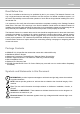
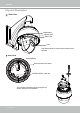
VIVOTEK Physical Description Outer View Reset Button Network LED Status LED Lens This drawing shows a camera with its dome cover removed. Inner View Camera Body Board-to-board Connector SD/SDHC/SDXC Card Slot The card slot is accessed by removing the top section using the T25 stardriver.
VIVOTEK Interface Section General I/O Terminal Block Spring Contacts for Dehumidifier Ethernet Ethernet 10/100 RJ45 Plug AC24V AC24V Reserved MIC IN Line OUT Audio GND RS485RS485+ DI GND DI4 DI3 DI2 DI1 DO2 DO1 DO+(12V) Status LED Item LED status Description 1 Steady red Power on and system booting Red LED off Power off 2 Steady red & Green blinking every 1 sec. Network normal (heartbeat) Steady red & Green LED off Network failed 3 Red blinking every 0.15 sec.
VIVOTEK DI/DO Diagram Please refer to the following illustration for the connection method. Please note that the maximum load on the DO pins is 50mA. GND GND VDC Camera Power (DO+ 12V) Camera Power Input BJT transistor Switch +12 VDC Max. Output Input BJT transistor Relay VDC Switch +12 VDC Output Relay IMPORTANT: 1. The camera can be driven by an Ethernet connection to a PoE Plus switch (30W output). You can connect both the PoE Plus and the 24V power for fail-safe redundancy. 2.
VIVOTEK Installation - for the Configuration w/ Extended Cables Hardware Installation IMPORTANT: The SD8364E series comes with or without the extended Ethernet and IO combo cables. Different configurations come with different ordering numbers. Therefore, the installation procedure can differ, and the procedures are separately described as follows. IMPORTANT: If your camera comes without the dehumidifier, you should examine whether the color of the silica gel inside the chassis has turned dark.
VIVOTEK Install the Wall-mount Bracket 1. The camera weighs 3.66kg. Select a rigid mounting location to prevent vibration to the camera. Attach the alignment sticker to the wall. 2. Drill 4 pilot holes (10mm in diameter and 4cm deep) into the wall, and then hammer in threaded anchors. Note that you should hammer the anchors with hex nuts on them so that the threaded poles will not be deformed! If preferred, drill another hole for routing cables. 3.
VIVOTEK Cabling Connections & Attach the Top Section 1. Hold your top section with one hand and pass all cables through the wallmount bracket. 5 4 1 3 2 2. Secure the top section to the wall mount bracket. Note that you should turn and orient the top section so that the C mark is facing a direction 15 degrees off the center line. Remove seal from the breathe hole on the top section if your camera comes with the dehumidifier.
VIVOTEK 3. Connect cables and use sealants and putties to make sure cable joints and the cabling hole are waterproof. 4. Secure the included ground wire to the dome cap, pass it through the mount bracket, and connect the other end to a grounded conduit later. 5. Use the included hex wrench to secure the top section. Mounting the Camera 1. Align the camera body with the top section. Align the alignment mark on the camera with that on the interface section. Push the camera up to match the top section. 2.
VIVOTEK Installation - for the Configuration w/o Extended Cables Hardware Installation 1. Connecting RJ45 Ethernet Cable RJ45 Cable Dimension (unit: mm) Use CAT5e cables only. Components of the Waterproof Connector Sealing Nut (A) Seal (B) Screw Nut (C) Housing (D) Gasket (E) 100 Assembling Steps 1 Prepare an Ethernet cable and strip part of the sheath. 2 Insert the housing into the screw nut. (C) 3 (D) Insert the seal into the housing. (B) Recommended cable gauge: O.D. 5.
VIVOTEK 2. Connecting Power and I/O Wires If you need to connect I/O wires and 24V power, disassemble the top section of the camera. It is highly recommended to complete the following before you can mount the speed dome camera at the installation site: Skip this section and move to Section 3-3 if you connect the Ethernet cable only. 1-3 1-1 Connect with the mount bracket Cabling through the dome cap and waterproof connectors 1-2 Plan the wire length and complete cabling to the Interface Section 2-1.
VIVOTEK 1. Disassemble the components of the waterproof connector into parts (A) ~ (E) as shown above. 2. Remove the plastic stopper from the bottom of the dome cap and keep the M20 hex nut for later use. 3. Depending on the number of wires, remove seals (C) from the rubber seal (B). 4. If you have external devices such as sensors and alarms, feed IO wires through the waterproof connector (E --> D --> B --> A) as the illustrated below.
VIVOTEK 2. Feed the Ethernet cable and IO wires through the mounting bracket, the openings on the dome cap, and to the interface section. Attach the rubber seal plug to dome cap for water proofing. 3. Secure the included ground wire to the dome cap, pass it through the mount bracket, and connect the other end to a grounded conduit later. 4. Remove seal from the breathe hole on the top section if your camera comes with the dehumidifier. 2 Mount bracket 4 Dome cap 3 Interface Section NOTE: 1.
VIVOTEK 1-3. Connect with the Mount Bracket Combine the components of the top section. 1. Press the seal ring into the groove on the interface section. Use the black machine screws (M4x8) to attach the interface section to the dome cap. Note that you should orient and align the spring contacts with the dehumidifier unit on the dome cap. 2. Secure the dome cap to the mount bracket. 3. Use the included hex wrench to secure the connection.
VIVOTEK 2. Mounting the Network Camera Shown below are the dimensions of the wall mount bracket and its mounting holes: You can find the installation instructions on VIVOTEK’s website for other options such as parapet mount: http://www.vivotek.com/web/ product/accessories.
VIVOTEK NOTE: Before mounting the camera, install an SD card if you prefer recording to local storage. 1. Mounting with Ethernet Connection Only 1. The camera weighs 3.66kg. Select a rigid mounting location to prevent vibration to the camera. Attach the alignment sticker to the wall. 2. Drill 4 pilot holes (10mm in diameter and 4cm deep) into the wall, and then hammer in threaded anchors.
VIVOTEK 2. Mounting with Ethernet & I/O Wires 1. The camera weighs 3.66kg. Select a rigid mounting location to prevent vibration to the camera. Attach the alignment sticker to the wall. 2. Drill 4 pilot holes (10mm in diameter and 4cm deep) into the wall, and then hammer in threaded anchors. Note that you should hammer the anchors with hex nuts on them so that the threaded poles will not be deformed! If preferred, drill another hole for routing cables. 3.
VIVOTEK Network Deployment Setting up the Network Camera over the Internet There are several ways to set up the Network Camera over the Internet. The first way is to set up the Network Camera behind a router. The second way is to utilize a static IP. The third way is to use PPPoE. Internet connection via a router Before setting up the Network Camera over the Internet, make sure you have a router and follow the steps below. 1.
VIVOTEK Internet. Please refer to Network Type on page 68 for details. For example, your router and IP settings may look like this: Device IP Address: internal IP Address: External Port (Mapped port on the port router) Public IP of router 122.146.57.120 LAN IP of router 192.168.2.1 Camera 1 192.168.2.10:80 122.146.57.120:8000 Camera 2 192.168.2.11:80 122.146.57.120:8001 ... ... ...
VIVOTEK Internet connection with static IP Choose this connection type if you are required to use a static IP for the Network Camera. Please refer to LAN on page 68 for details. Internet connection via PPPoE (Point-to-Point over Ethernet) Choose this connection type if you are connected to the Internet via a DSL Line. Please refer to PPPoE on page 69 for details. General Connection 1. Connect the Network Camera's Ethernet cable (CAT5e) to a PoE Plus switch.
VIVOTEK Software Installation Installation Wizard 2 (IW2), free-bundled software included on the product CD, helps you set up your Network Camera on the LAN. 1. Install IW2 under the Software Utility directory from the software CD. Double click the IW2 shortcut on your desktop to launch the program. IW2 Installation Wizard 2 2. The program will conduct an analysis of your network environment. After your network environment is analyzed, please click Next to continue the program. 3.
VIVOTEK Ready to Use 1. A browser session with the Network Camera should prompt as shown below. 2. You should be able to see live video from your camera. You may also install the 32-channel recording software from the software CD in a deployment consisting of multiple cameras. For its installation details, please refer to its related documents. 20x IMPORTANT: • Currently the Network Camera utilizes a 32-bit ActiveX plugin.
VIVOTEK Accessing the Network Camera This chapter explains how to access the Network Camera through web browsers, RTSP players, 3GPP-compatible mobile devices, and VIVOTEK recording software. Using Web Browsers Use Installation Wizard 2 (IW2) to access to the Network Cameras on the LAN. If your network environment is not a LAN, follow these steps to access the Netwotk Camera: 1. Launch your web browser (e.g., Microsoft® Internet Explorer or Mozilla Firefox). 2.
VIVOTEK ► By default, the Network Camera is not password-protected. To prevent unauthorized access, it is highly recommended to set a password for the Network Camera. For more information about how to enable password protection, please refer to Security on page 86. ► If you see a dialog box indicating that your security settings prohibit running ActiveX ® Controls, please enable the ActiveX ® Controls for your browser. 1. Choose Tools > Internet Options > Security > Custom Level. 2.
VIVOTEK Using RTSP Players To view the H.264/MPEG-4 streaming media using RTSP players, you can use one of the following players that support RTSP streaming. Quick Time Player VLC Media Player VLCthe media player 1. Launch RTSP player. 2. Choose File > Open mpegable PlayerURL. An URL dialog box will pop up. 3.
VIVOTEK Using 3GPP-compatible Mobile Devices To view the streaming media through 3GPP-compatible mobile devices, make sure the Network Camera can be accessed over the Internet. For more information on how to set up the Network Camera over the Internet, please refer to Setup the Network Camera over the Internet on page 21. To utilize this feature, please check the following settings on your Network Camera: 1.
VIVOTEK Using VIVOTEK Recording Software The product software CD also contains recording software, allowing simultaneous monitoring and video recording for multiple Network Cameras. Please install the recording software; then launch the program to add the Network Camera to the Channel list. For detailed information about how to use the recording software, please refer to the user’s manual of the software or download it from http://www.vivotek.com.
VIVOTEK Main Page This chapter explains the layout of the main page. It is composed of the following sections: VIVOTEK INC. Logo, Host Name, Camera Control Area, Configuration Area, and Live Video Window. VIVOTEK INC. Logo Resize Buttons Host Name Configuration Area Camera Control Area Hide Button Live View Window Mouse and Screen Control In addition to the use of a joystick, mouse control is also supported by the web session.
VIVOTEK VIVOTEK INC. Logo Click this logo to visit the VIVOTEK website. Host Name The host name can be customized to fit your needs. For more information, please refer to System on page 43. Camera Control Area Video Stream: This Network Camera supports multiple streams (stream 1 ~ 4) simultaneously. You can select either one for live viewing. For more information about multiple streams, please refer to page 63 for detailed information.
VIVOTEK Pan /Tilt /Zoom /Focus speed: Adjust the speed of Pan/ Tilt/ Zoom/ Focus: Pan speed Tilt speed Zoom speed Focus speed -5 -5 -5 -5 -4 -4 -4 -4 -3 -3 -3 -3 -2 -2 -2 -2 -1 -1 -1 -1 0 0 0 0 1 1 1 1 2 2 2 2 3 3 3 3 4 4 4 4 5 5 5 5 Slower Faster Note that mouse screen control is also supported. You can refer to page 99 for related information. Configuration Area Client Settings: Click this button to access the client setting page.
VIVOTEK Resize Buttons : Click the Auto button, the video cell will resize automatically to fit the monitor. Click 100% is to display the original homepage size. Click 50% is to resize the homepage to 50% of its original size. Click 25% is to resize the homepage to 25% of its original size. Go to If you have preset PTZ positions, these positions will be available in the Go to menu. Please refer to page 99 for more information.
VIVOTEK Snapshot: Click this button to capture and save still images. The captured images will be displayed in a pop-up window. Right-click the image and choose Save Picture As to save it in JPEG (*.jpg) or BMP (*.bmp) format. Digital Zoom: Click and uncheck “Disable digital zoom” to enable the zoom operation. The navigation screen indicates the part of the image being magnified. To control the zoom level, drag the slider bar. To move to a different area you want to magnify, drag the navigation screen.
VIVOTEK ■ The following window is displayed when the video mode is set to MJPEG: Video Title Title and Time Video (HTTP-V) 2011/03/10 17:08:56 Time Video 17:08:56 2011/03/10 Video Control Buttons Video Title: The video title can be configured. For more information, please refer to Media > Image on page 53. Time: Display the current time. For more information, please refer to Media > Image on page 53. Title and Time: Video title and time can be stamped on the streaming video.
VIVOTEK Client Settings This chapter explains how to select the stream transmission mode and saving options on the local computer. When completed with the settings on this page, click Save on the page bottom to enable the settings. H.264/MPEG-4 Media Options H.264/MPEG-4 Media Options Select to stream video or audio data or both. This is enabled only when the video mode is set to H.264 or MPEG-4. H.264/MPEG-4 Protocol Options H.
VIVOTEK MP4 Saving Options Users can record live video as they are watching it by clicking the button - Start MP4 Recording - on the main page. Here, you can specify the storage destination and file name. Folder: Specify a storage destination for the recorded video files. File name prefix: Enter the text that will be appended to the front of the video file name. Add date and time suffix to the file name: Select this option to append the date and time to the end of the file name of the recorded videos.
VIVOTEK Joystick Settings Enable Joystick Connect to the USB plug of the joystick to a USB port on your management computer. Once a USB joystick is connected, the related joystick configuration will be available on the Client settings window. The joystick should work properly without installing any other driver or software. Then you can begin to configure the joystick settings of connected devices. Please follow the instructions below to enable joystick settings. 1. Click on the Configure buttons button.
VIVOTEK Buttons Configuration In the Joystick Settings window, you can use the combinations of pull-down menus, Actions and Button number, to assign joystick buttons with different functions. The number of buttons may differ from the joystick you attached. Please follow the steps below to configure your joystick buttons: 1. Select the number of the button you want to configure from its pull-down list. For example: Assign Preset 1 (move to preset 1 position) to Button 1. 2.
VIVOTEK NOTE: • • If you want to assign Preset actions to your joystick, the PTZ preset locations should be configured in advance. If your joystick is not working properly, it may need to be calibrated. Click the Calibrate button to open the Game Controllers window located in Microsoft Windows control panel and follow the instructions for trouble shooting. • The joystick will appear in the Game Controllers list in the Windows Control panel.
VIVOTEK Configuration Click Configuration on the main page to enter the camera setting pages. Note that only Administrators can access the configuration page. Please refer to page 86 Security > User Account for how to configure access rights for different users. Navigation Area Configuration List Firmware Version Each function on the configuration list will be explained in the following sections.
VIVOTEK System > General settings This section explains how to configure the basic settings for the Network Camera, such as the host name and system time. It is composed of the following two columns: System and System Time. System Host name: Enter a desired name for the Network Camera. The text will be displayed at the top of the main page. System time Keep current date and time: Select this option to preserve the current date and time of the Network Camera.
VIVOTEK System > Homepage layout This section explains how to set up your own customized homepage layout. General settings This column shows the settings of your hompage layout. You can manually select the background and font colors in Theme Options (the second tab on this page). The settings will be displayed automatically in this Preview field. The following shows the homepage using the default settings: ■ Hide Powered by VIVOTEK: If you check this item, such wording will be removed from the homepage.
VIVOTEK Theme Options Here you can change the color of your homepage layout. There are three types of preset patterns for you to choose from. The new layout will simultaneously appear in the Preview filed. Click Save to enable the settings.
VIVOTEK ■ Follow the steps below to set up the customed homepage: 1. Click Custom on the left column. 2. A double-click on the color selection area (the right hand side column) will bring up a color palette window. Color Selector Custom Pattern 3. The palette window will pop up as shown below. 2 3 1 4 4. Drag the slider bar and click on the left square to select a desired color. 5. The selected color will be displayed in the corresponding fields and in the Preview column. 6.
VIVOTEK System > Logs This section explains how to configure the Network Camera to send the system log to the remote server as backup. Log server settings Follow the steps below to set up the remote log: 1. Select Enable remote log. 2. In the IP address text box, enter the IP address of the remote server. 2. In the port text box, enter the port number of the remote server. 3. When completed, click Save to enable the setting.
VIVOTEK Access log Access log displays the access time and IP address of all viewers (including operators and administrators) in a chronological order. The access log is stored in the Network Camera’s buffer area and will be overwritten when reaching a certain limit. System > Parameters The View Parameters page lists the entire system’s parameters in an alphabetical order. If you need technical assistance, please provide the information listed on this page.
VIVOTEK System > Maintenance This chapter explains how to restore the Network Camera to factory default, reboot, upgrade firmware version, etc. General settings > Upgrade firmware This feature allows you to upgrade the firmware of your Network Camera. It takes a few minutes to complete the process. Note: Do not power off the Network Camera during the upgrade! Follow the steps below to upgrade the firmware: 1. Download the latest firmware file from the VIVOTEK website. The file is in .pkg file format. 2.
VIVOTEK General settings > Restore This feature allows you to restore the Network Camera’s factory defaults. Network: Select this option to retain the Network Type settings (please refer to Network Type on page 68). Daylight Saving Time: Select this option to retain the Daylight Saving Time settings (please refer to Import/Export files below on this page). Custom Language: Select this option to retain the Custom Language settings.
VIVOTEK 3. Open and edit the file using Microsoft® Notepad and locate your time zone in the strings; set the start and end time of DST. When completed, save the file. In the example below, DST begins each year at 2:00 a.m. on the second Sunday in March and ends at 2:00 a.m. on the first Sunday in November. Update daylight saving time rules: Click Browse… and specify the XML file to update.
VIVOTEK The following message is displayed when attempting to upload an incorrect file format. Export language file: Click to export language strings. VIVOTEK provides nine languages: English, Deutsch, Español, Français, Italiano, 日本語, Português, 簡体中文, and 繁體中文. Update custom language file: Click Browse… and specify your own custom language file to upload. Export configuration file: Click to export all parameters for the device and user-defined scripts.
VIVOTEK Media > Image This section explains how to configure the image settings of the Network Camera. It is composed of the following four columns: General settings, Picture settings, Exposure, and Privacy mask. General settings Video title Show_timestamp and video title in videos_and_snapshots: Enter a name that will be displayed on the title bar of the live video as the picture shown below.
VIVOTEK Image settings On this page, you can tune the White balance and Image adjustment settings. Sensor Setting 1: For normal situations Sensor Setting 2: For special situations White balance: Adjust the value for the best color temperature. ■ Select one of the white balance modes: 1. Outdoor (system default): Using this mode enables the camera to capture images with natural white balance observable in the morning. 2. Fluorescent light: 3,200K base mode, suitable for indoor applications. 3.
VIVOTEK Enable 3D Noise reduction ■ Check to enable noise reduction in order to reduce noises and flickers in image. This applies to the onboard 3D Noise Reduction feature. Use the pull-down menu to adjust the reduction strength. Note that applying this function to the video channel will consume system computing power. 3D Noise Reduction is mostly applied in low-light conditions. When enabled in a low-light condition with fast moving objects, trails of after-images may occur.
VIVOTEK Exposure control: ■ Exposure level: You can manually set the Exposure level, which ranges from -2.0 to +2.0 (dark to bright). You can also select other values from the Exposure mode menus and select a preferred scenario or manually configure the associated settings. You may prefer a shorter shutter time to better capture moving objects, while a faster shutter reduces light and needs to be compensated by electrical brightness gains.
VIVOTEK NOTE: • When Iris Priority is selected for the Exposure mode, the tunable aperture size is related to zoom ratio. When using different zoom ratios, the range of aperture sizes can be different. When zoom ratio is 0x, the range of iris sizes is F1.6~F14. When zoom ratio is 20x, the iris size is F3.4. See below for the corresponding maximum iris sizes at different zoom ratios: Zoom F no. ratio Zoom F no. ratio Zoom F no. ratio Zoom F no. ratio Zoom F no. ratio Zoom F no. ratio Zoom F no.
VIVOTEK ■ Back light compensation: This option is only available when the Auto mode is selected for the Exposure setting. This option enables light compensation for images that are too dark to recognize; for example, for the dark side of objects that is posed against bright sunlight. This option is disabled if you enable the WDR function. ■ Maximum gain control: Select a maximum value for the electronic gain from the slide bar. The gain value also has its effect on the sensitivity of the IR cut filter.
VIVOTEK Day/Night Settings ■ Turn on external IR illuminator in night mode The camera’s digital output signal can be connected to external IR lights to turn it on when the camera detects low light conditions and enters the night mode. IR cut filter With a removable IR-cut filter, this Network Camera can automatically remove the filter to let IR light enter the light sensor during low light conditions. ■ Auto mode The Network Camera automatically removes the filter by judging the level of ambient light.
VIVOTEK Exposure Profile: (Only available when the IR cut filter is not set to the Auto mode) If you want to configure another sensor and exposure setting for an individual day/night/schedule mode, please click Profile to open the Profile of exposure settings page as shown below. Activated period: Select the mode this profile to apply to: Day mode, Night mode, or Schedule mode. Please manually enter a range of time if you choose Schedule mode. Then check Save to take effect.
VIVOTEK Privacy mask Click Privacy Mask to open the settings page. On this page, you can block out sensitive view areas to address privacy concerns. NOTE: 1. The navigation buttons here also support the continuous move. You can click and hold down the button to move across the screen until you release the button. 2. You can not create privacy masks at angles between +70° and -70°. 0° ■ To set the privacy mask windows, follow the steps below: 0° -70° 90° +70° 1.
VIVOTEK NOTE: • • • • The camera supports "3D Privacy Mask." Privacy masks should stay at the same positions regardless of how the camera lens may move. When the "Enabled privacy mask" checkbox is deselected, no privacy masks will appear on screen. Up to 24 privacy mask windows can be configured over the camera's hemispheric coverage. If you want to delete a privacy mask window, select its name from the pull-down menu at the bottom, and then click Delete to remove it.
VIVOTEK Media > Video FOV This Network Camera operates with either the Full HD mode or the 720P mode. When in the 720P resolution, the camera can deliver video streams at an exceptional 60fps frame rate. Stream settings This Network Camera supports multiple streams with frame sizes ranging from 176 x 144 to 1920 x 1080 pixels. The definition of multiple streams: ■ Stream 1: Users can define the Frame sizes, compression format, image quality, etc.
VIVOTEK Click the stream item to display the detailed information. . This Network Camera offers real-time H.264, MPEG-4, and MJPEG compression standards (Multiple Codec) for real-time viewing. If the H.264 / MPEG-4 mode is selected, the video is streamed via RTSP protocol. There are several parameters through which you can adjust the video performance: NOTE: ► Video quality and fixed quality refers to the compression rate, so a lower value will produce higher quality.
VIVOTEK ■ Frame size You can set up different video resolution for different viewing devices. For example, set a smaller frame size and lower bit rate for remote viewing on mobile phones and a larger video size and a higher bit rate for live viewing on web browsers. Note that a larger frame size takes up more bandwidth. ■ Maximum frame rate This limits the maximum refresh frame rate per second. Set the frame rate higher for smoother video quality and for recognizing moving objects in the field of view.
VIVOTEK NOTE: ► Video quality and fixed quality refers to the compression rate, so a lower value will produce higher quality. ► Converting high-quality video may significantly increase the CPU loading, and you may encounter streaming disconnection or video loss while capturing a complicated scene. In the event of occurence, we suggest you customize a lower video resolution or reduce the frame rate to obtain smooth video.
VIVOTEK IMPORTANT: The network camera does not come with embedded microphone. An external microphone will be necessary especially if you prefer the Audio Detection feature. By default, the Audio setting is muted, and you need to manually uncheck the Mute option.
VIVOTEK Network > General settings This section explains how to configure a wired network connection for the Network Camera. Network Type LAN Select this option when the Network Camera is deployed on a local area network (LAN) and is intended to be accessed by local computers. The default setting for the Network Type is LAN. Please rememer to click on the Save button when you complete the Network setting.
VIVOTEK Primary DNS: The primary domain name server that translates host names into IP addresses. Secondary DNS: Secondary domain name server that backs up the Primary DNS. Primary WINS server: The primary WINS server that maintains the database of computer names and IP addresses. Secondary WINS server: The secondary WINS server that maintains the database of computer names and IP addresses.
VIVOTEK NOTE: ► If the default ports are already used by other devices connected to the same router, the Network Camera will select other ports for the Network Camera. ► If UPnP TM is not supported by your router, you will see the following message: Error: Router does not support UPnP port forwarding. ► Steps to enable the UPnP TM user interface on your computer: Note that you must log on to the computer as a system administrator to install the UPnP TM components. 1.
VIVOTEK 4. In the Networking Services dialog box, select Universal Plug and Play and click OK. 5. Click Next in the following window. 6. Click Finish. UPnP TM is enabled. ► How does UPnP TM work? UPnP TM networking technology provides automatic IP configuration and dynamic discovery of devices added to a network. Services and capabilities offered by networked devices, such as printing and file sharing, are available among each other without the need for cumbersome network configuration.
VIVOTEK Enable IPv6 Select this option and click Save to enable IPv6 settings. Please note that this only works if your network environment and hardware equipment support IPv6. The browser should be Microsoft® Internet Explorer 6.5, Mozilla Firefox 3.0 or above. When IPv6 is enabled, by default, the network camera will listen to router advertisements and be assigned with a link-local IPv6 address accordingly. IPv6 Information: Click this button to obtain the IPv6 information as shown below.
VIVOTEK Please follow the steps below to link to an IPv6 address: 1. Open your web browser. 2. Enter the link-global or link-local IPv6 address in the address bar of your web browser. 3. The format should be: http://[2001:0c08:2500:0002:0202:d1ff:fe04:65f4]/ IPv6 address 4. Press Enter on the keyboard or click Refresh button to refresh the webpage.
VIVOTEK Port HTTPS port: By default, the HTTPS port is set to 443. It can also be assigned to another port number between 1025 and 65535. Two way audio port: By default, the two way audio port is set to 5060. Also, it can also be assigned to another port number between 1025 and 65535. The Network Camera supports two way audio communication so that operators can transmit and receive audio simultaneously.
VIVOTEK Audio is being transmitted to the Network Camera 2011/06/09 17:08:56 Mute Talk Button Mic Volume Click to enable audio transmission to the Network Camera; click to turn off the audio. To stop talking, click again. microphone; click to adjust the volume of FTP port: The FTP server allows the user to save recorded video clips. You can utilize VIVOTEK's Installation Wizard 2 to upgrade the firmware via FTP server. By default, the FTP port is set to 21.
VIVOTEK Network > Streaming protocols HTTP streaming To utilize HTTP authentication, make sure that your have set a password for the Network Camera first; please refer to Security > User account on page 86 for details. Authentication: Depending on your network security requirements, the Network Camera provides two types of security settings for an HTTP transaction: basic and digest.
VIVOTEK URL command -- http://:/ For example, when the Access name for stream 2 is set to video2.mjpg: 1. Launch the Mozilla Firefox browser. 2. Type the above URL command in the address bar. Press Enter. 3. The JPEG images will be displayed in your web browser.
VIVOTEK Authentication: Depending on your network security requirements, the Network Camera provides three types of security settings for streaming via RTSP protocol: disable, basic, and digest. If basic authentication is selected, the password is sent in plain text format, but there can be potential risks of it being intercepted. If digest authentication is selected, user credentials are encrypted using MD5 algorithm, thus providing better protection against unauthorized access.
VIVOTEK Multicast settings for stream 1, 2, 3, and 4: Click the items to display the detailed configuration information. Select the Always multicast option to enable multicast for video streams. Unicast video transmission delivers a stream through point-to-point transmission; multicast, on the other hand, sends a stream to the multicast group address and allows multiple clients to acquire the stream at the same time by requesting a copy from the multicast group address.
VIVOTEK Network > DDNS This section explains how to configure the dynamic domain name service for the Network Camera. DDNS is a service that allows your Network Camera, especially when assigned with a dynamic IP address, to have a fixed host and domain name. Express link Express Link is a free service provided by VIVOTEK server, which allows users to register a domain name for a network device. One URL can only be mapped to one MAC address.
VIVOTEK Manual setup DDNS: Dynamic domain name service Enable DDNS: Select this option to enable the DDNS setting. Provider: Select a DDNS provider from the provider drop-down list. VIVOTEK offers Safe100.net, a free dynamic domain name service, to VIVOTEK customers. It is recommended that you register Safe100.net to access VIVOTEK’s Network Cameras from the Internet. Additionally, we offer other DDNS providers, such as Dyndns.org(Dynamic), Dyndns.org(Custom), CustomSafe100, dyn-interfree.it.
VIVOTEK [Register] Successfully Your account information has been mailed to registered e-mail address 4. Select Enable DDNS and click Save to enable the setting. ■ CustomSafe100 VIVOTEK offers documents to establish a CustomSafe100 DDNS server for distributors and system integrators. You can use CustomSafe100 to register a dynamic domain name if your distributor or system integrators offer such services. 1. In the DDNS column, select CustomSafe100 from the drop-down list. 2.
VIVOTEK Network > QoS (Quality of Service) Quality of Service refers to a resource reservation control mechanism, which guarantees a certain quality to different services on the network. Quality of service guarantees are important if the network capacity is insufficient, especially for real-time streaming multimedia applications. Quality can be defined as, for instance, a maintained level of bit rate, low latency, no packet dropping, etc.
VIVOTEK QoS/DSCP (the DiffServ model) DSCP-ECN defines QoS at Layer 3 (Network Layer). The Differentiated Services (DiffServ) model is based on packet marking and router queuing disciplines. The marking is done by adding a field to the IP header, called the DSCP (Differentiated Services Codepoint). This is a 6-bit field that provides 64 different class IDs. It gives an indication of how a given packet is to be forwarded, known as the Per Hop Behavior (PHB).
VIVOTEK Network > SNMP (Simple Network Management Protocol) This section explains how to use the SNMP on the network camera. The Simple Network Management Protocol is an application layer protocol that facilitates the exchange of management information between network devices. It helps network administrators to remotely manage network devices and find, solve network problems with ease.
VIVOTEK Security > User Account This section explains how to enable password protection and create multiple accounts. Root Password The administrator account name is “root”, which is permanent and can not be deleted. If you want to add more accounts in the Manage User column, please apply the password for the “root” account first. 1. Type the password identically in both text boxes, then click Save to enable password protection. 2.
VIVOTEK Security > HTTPS (Hypertext Transfer Protocol over SSL) This section explains how to enable authentication and encrypted communication over SSL (Secure Socket Layer). It helps protect streaming data transmission over the Internet on higher security level. Create and Install Certificate Method Before using HTTPS for communication with the Network Camera, a Certificate must be created first.
VIVOTEK 5. Click Save to preserve your configuration, and your current session with the camera will change to the encrypted connection. 6. If your web session does not automatically change to an encrypted HTTPS session, click Home to return to the main page. Change the URL address from “http://” to “https://“ in the address bar and press Enter on your keyboard. Some Security Alert dialogs will pop up. Click OK or Yes to enable HTTPS. https:// https://192.168.5.151/index.
VIVOTEK Create certificate request and install 1. Select the option from the Method pull-down menu. 2. Click Create certificate to proceed. 3. The following information will show up in a pop-up window after clicking Create. Then click Save to generate the certificate request. 4. The Certificate request window will prompt. If you see the following Information bar, click OK and click on the Information bar at the top of the page to allow pop-ups.
VIVOTEK 5. Look for a trusted certificate authority, such as Symantec’s VeriSign Authentication Services, that issues digital certificates. Sign in and purchase the SSL certification service. Copy the certificate request from your request prompt and paste it in the CA’s signing request window. Proceed with the rest of the process as CA’s instructions on their webpage. 6. Once completed, your SSL certificate should be delivered to you via an email or other means.
VIVOTEK 7. Open a new edit, paste the certificate contents, and press ENTER at the end of the contents to add an empty line. 8. Convert file format from DOS to UNIX. Open File menu > Conversions > DOS to Unix.
VIVOTEK 9. Save the edit using the “.crt” extension, using a file name like “CAcert.crt.” 10. Return to the original firmware session, use the Browse button to locate the crt certificate file, and click Upload to enable the certification.
VIVOTEK 11. When the certifice file is successfully loaded, its status will be stated as Active. Note that a certificate must have been created and installed before you can click on the “Save" button for the configuration to take effect. 12.To begin an encrypted HTTPS session, click Home to return to the main page. Change the URL address from “http://” to “https://“ in the address bar and press Enter on your keyboard. Some Security Alert dialogs will pop up. Click OK or Yes to enable HTTPS.
VIVOTEK Security > Access List This section explains how to control access permission by verifying the client PC’s IP address. General Settings Maximum number of concurrent streaming connection(s) limited to: Simultaneous live viewing for 1~10 clients (including all streams). The default value is 10. If you modify the value and click Save, all current connections will be disconnected and automatically attempt to re-link (IE Explorer or Quick Time Player).
VIVOTEK ■ Disconnect: If you want to break off the current connections, please select them and click this button. Please note that those checked connections will only be disconnected temporarily and they will automatically retry a connection (IE Explore or Quick Time Player). Enable access list filtering: Check this item and click Save if you want to enable the access list filtering function. Filter Filter type: Select Allow or Deny as the filter type.
VIVOTEK Network: This rule allows the user to assign a network address and corresponding subnet mask to the Allow/Deny List in the CIDR format, e.g. 192.168.xx.xx/24. For example: IP address 192.168.2.x will be blocked. Range: This rule allows the user to assign a range of IP addresses to the Allow/Deny List. Note: This rule is only applicable to IPv4 addresses.
VIVOTEK Security > IEEE 802.1x Enable this function if your network environment uses IEEE 802.1x, which is a port-based network access control. The network devices, intermediary switch/access point/hub, and RADIUS server must support and have their 802.1x settings enabled. The 802.1x standard is designed to enhance the security of local area networks, which provides authentication to network devices (clients) attached to a network port (wired or wireless).
VIVOTEK 3. When all settings are complete, move the Network Camera to the protected LAN by connecting it to an 802.1x enabled switch. The devices will then start the authentication automatically. NOTE: ► Below is the authentication process for 802.1x: 1. The Certificate Authority (CA) provides the required signed certificates to the Network Camera (the supplicant) and the RADIUS Server (the authentication server). 2. A Network Camera requests access to the protected LAN using 802.
VIVOTEK PTZ > PTZ settings This section explains how to control the Network Camera’s Pan/Tilt/Zoom operation. The camera comes with built-in PTZ mechanisms. NOTE: 1 1 The navigation buttons here also support the continuous move. You can click and hold down the button to move across the screen until you release the button. 7 2 5 3 6 4 8 Preset positions and patrol settings In the PTZ settings page, you can select preset positions for the camera to patrol.
VIVOTEK Misc. settings: Use the checkboxes and the pull-down menus for the camera to automatically resume the previous action or return to the home position after the camera has stayed idle for a period of time. PTZ control panel operation mode: This determines how your mouse and PTZ control panel works on a live view window. The Continuous move allows your screen control action to continue as long as you click and hold down the left mouse button.
VIVOTEK The Zoom factor display: This option is enabled by default, and zoom ratio is displayed along with the video title on the upper left corner of a view cell. Apply previous action if the camera idles for __(1~999) seconds: You can assign an action to be taken when the camera sits idle for a configurable period time. For example, you can let camera resume a patrol tour. The resumed patrol will continue from the last preset position. You may also let the camera return to the home position.
VIVOTEK Auto tracking In this window, you can modify the minimum object size as the triggering factor while performing the Auto Tracking function. You can move the camera view to an area of your interest, estimate, and define the possible size of objects. For example, you can designate the object size such as that of a human trespasser. The silhouette of the tresspasser must be larger than the whole of the object size square box. The minimum object size is 30x30 pixels within a 320x420 view window.
VIVOTEK Auto tracking is configured by designating the minimum object size. Moving objects that entered the current region of view will trigger the tracking action. Auto tracking, if applied, is designed to track an intruder in a place where human traffic is not heavy, such as a warehouse or a load area. Heavy traffic can result in a constant shift of tracked objects, and reduce the effectiveness of the feature. NOTE: 1. The speed dome can track one object at a time. 2.
VIVOTEK Event > Event settings This section explains how to configure the Network Camera to responds to particular situations (event). A typical application is that when a motion is detected, the Network Camera sends buffered images to an FTP server or e-mail address as notifications. Click on Help, there is an illustration shown in the pop-up window explaining that an event can be triggered by many sources, such as motion detection or external digital input devices.
VIVOTEK ■ Event name: Enter a name for the event setting. ■ Enable this event: Select this option to enable the event setting. ■ Priority: Select the relative importance of this event (High, Normal, or Low). Events with a higher priority setting will be executed first. ■ Detect next motion detection or digital input after motion detection after a motion is detected.
VIVOTEK ■ Audio detection A preset threshold can be configured with an external microphone as the trigger to system event. The triggering condition can be an input exceeding or falling below a threshold. Audio detection can take place as a complement to motion detection or as a method to detect activities not covered by the camera's view. Please refer to page 121 Applications > Audio detection for more details.
VIVOTEK settings so that the Network Camera will know what action to take (such as which server to send the media files to) when a trigger is activated. NOTE: If you configured a motion detection window as a trigger, the motion detection may become invalid when the camera’s field of view moved away from the detection window.
VIVOTEK Add server Click Add server to unfold the server setting window. You can specify where the notification messages are sent when a trigger is activated. A total of 5 server settings can be configured. There are four choices of server types available: Email, FTP, HTTP, and Network storage. Select the item to display the detailed configuration options. You can configure either one or all of them. Server type - Email Select to send the media files via email when a trigger is activated.
VIVOTEK To verify if the email settings are correctly configured, click Test. The result will be shown in a pop-up window. If successful, you will also receive an email indicating the result. Click Save server to enable the settings, then click Close to exit the Add server page. After you set up the first event server, a new item for event server will automatically show up on the Server list. If you wish to add more server options, click Add server.
VIVOTEK ■ Passive mode Most firewalls do not accept new connections initiated from external requests. If the FTP server supports passive mode, select this option to enable passive mode FTP and allow data transmission to pass through the firewall. To verify if the FTP settings are correctly configured, click Test. The result will be shown in a pop-up window as shown below. If successful, you will also receive a test.txt file on the FTP server.
VIVOTEK Network storage: Select to send the media files to a network storage location when a trigger is activated. Please refer to NAS server on page 128 for details. Click Save server to enable the settings, then click Close to exit the Add server page. ■ SD Test: Click to test your SD card. The system will display a message indicating success or failure. If you want to use your SD card for local storage, please format it before use. Please refer to page 131 for detailed information.
VIVOTEK Add media Click Add media to open the media setting window. You can specify the type of media that will be sent and preserved when a trigger is activated. A total of 5 media settings can be configured. There are three choices of media types available: Snapshot, Video Clip, and System log. Select the item to display the detailed configuration options. You can configure either one or all of them. Media type - Snapshot Select to send snapshots when a trigger is activated.
VIVOTEK ■ Add date and time suffix to the file name Select this option to add a date/time suffix to the file name. For example: Snapshot_20110320_100341 File name prefix Date and time suffix The format is: YYYYMMDD_HHMMSS Click Save media to enable the settings, then click Close to exit the Add media page. After you set up the first media server, a drop-down menu of existing medias will be available on the Media list. If you wish to add more media options, click Add media again.
VIVOTEK ■ Maximum duration Specify the maximum recording duration in seconds. Up to 20 seconds can be set. For example, if pre-event recording is set to 5 seconds and the maximum duration is set to 10 seconds, the Network Camera continues to record for another 4 seconds after a trigger is activated. 1 sec. 2 sec. 3 sec. 4 sec. 5 sec. 6 sec. 7 sec. 8 sec. 9 sec. 10 sec. Trigger Activation ■ Maximum file size Specify the maximum file size allowed.
VIVOTEK ■ View: Click this button to open a file list window. This function only apllies when an SD card and networked storage are available. If you click View button of SD card, a Local storage page will pop up for you to manage recorded files on SD card. For more information about Local storage, please refer to page 131. If you click View button of Network storage, a file directory window will pop up for you to view recorded data on Network storage.
VIVOTEK Here is an example of the Event setting: When completed the settings with steps 1~3 to arrange Schedule, Trigger, and Action of an event, click Save event to enable the settings and click Close to exit the page.
VIVOTEK When the Event Status is ON, once an event is triggered by motion detection, the Network Camera will automatically send snapshots via e-mails. If you want to stop the event trigger, you can click ON to turn it to OFF status or click Delete to remove the event setting. To remove a server setting from the list, select a server name and click Delete. Note that you can only delete a server setting when the server setting is currently not applied to an event setting.
VIVOTEK Applications > Motion detection This section explains how to configure the Network Camera to enable motion detection. A total of three motion detection windows can be configured. Motion Detection Setting 1: For normal situations Follow the steps below to enable motion detection: Follow the steps below to enable motion detection: Motion Detection Setting 2: For special situations 1. Click New to add a new motion detection window. 2.
VIVOTEK A green bar indicates that even though motions have been detected, the event has not been triggered because the image variations still fall under the defined threshold. Percentage = 30% If you want to configure other motion detection settings for day/night/schedule mode, please click Profile to open the Motion Detection Profile Settings page as shown below. A total of three motion detection windows can be configured on this page as well. Please follow the steps beolw to set up a profile: 1.
VIVOTEK NOTE: ► How does motion detection work? A C B D There are two motion detection parameters: Sensitivity and Percentage. In the illustration above, frame A and frame B are two sequential images. Pixel differences between the two frames are detected and highlighted in gray (frame C) and will be compared with the sensitivity setting. Sensitivity is a value that expresses the sensitivity to moving objects.
VIVOTEK Applications > DI and DO Digital input: Select High or Low to define normal status for the digital input. Connect a digital input from a sensor device to the camera, the Network Camera will report the current signal status. You may then configure the Normal status (non-trigger status) as High or Low. Digital output: Select High or Low to define normal status for the digital output. Connect an output line to an external device, the Network Camera will report the current signal status.
VIVOTEK Applications > Audio detection Audio detection, along with video motion detection, is applicable in the following scenarios: 1. Detection of activities not covered by camera view, e.g., a loud input by gun shots or breaking a door/ window. 2. A usually noisy environment, such as a factory, suddenly becomes quiet due to a breakdown of machines. 3. A PTZ camera can be directed to turn to a preset point by the occurrence of audio events. 4.
VIVOTEK You can use the Profile window to configure a different Audio detection setting. For example, a place can be noisy in the day time and become very quiet in the night. 1. Click on the Enable this profile checkbox. Once the Audio detection window is opened, the current sound input will be interactively indicated by a fluctuating yellow wave diagram. 2. Use a mouse click to drag the Alarm level tab to a preferred location on the slide bar. 3. Select the Day, Night, or Schedule mode check circles.
VIVOTEK Applications > VADP (VIVOTEK Application Development Platform) Users can store and execute VIVOTEK's or 3rd-party software modules onto the camera's flash memory or SD card. These software modules can apply in video analysis for intelligent video applications such as license plate recognition, object counting, or as an agent for edge recording, etc. • Once the software package is successfully uploaded, the module configuration (vadp.xml) information is displayed.
VIVOTEK To start a module, select the checkcircle in front, and click the Start button. If you should need to remove a module, select the checkcircle in front and then click the Stop button. By then the module status will become OFF, and the X button will appear at the end of the row. Click on the X button to remove an existing module. When prompted by a confirm message, Click Yes to proceed.
VIVOTEK Recording > Recording settings This section explains how to configure the recording settings for the Network Camera. Recording Settings Insert your SD card and click here to test NOTE: ► Please remember to format your SD card when using it for the first time. Please refer to page 131 for detailed information. Recording Settings Click Add to open the recording setting window. On this page, you can define the adaptive recording, recording source, recording schedule, and recording capacity.
VIVOTEK If you enable adaptive recording and enable time-shift cache stream on Camera A, only when an event is triggered on Camera A will the server record video streams in the full frame rate; otherwise, it will only request the I frame data during normal monitoring, thus effectively save lots of bandwidth and storage. NOTE: ► To enable adaptive recording, please make sure you’ve set up the trigger source such as Motion Detection, DI Device, or Manual Trigger.
VIVOTEK 2. Destination You can select the SD card or network attached storage (NAS) for recording video files. NAS server Click Add NAS server to open the server setting window and follow the steps below to set up: 1. Fill in the information for your server. For example: 3 Network storage path (\\server name or IP address\folder name) 1 User name and password for your server 2 4 2. Click Test to check the setting. The result will be shown in the pop-up window.
VIVOTEK If successful, you will receive a test.txt file on the network storage server. 3. Enter a server name. 4. Click Save to complete the settings and click Close to exit the page. ■ Capacity: You can select either the entire storage space available or specify a reserved space. The recording size limit must be larger than the reserved space for cyclic recording.
VIVOTEK this page. When the system begins recording, it will send the recorded files to a networked storage or SD card. The new recording name will appear on the recording page as shown below. To remove a recording setting from the list, select it and click Delete. ■ Video (Name): Click to open the Recording settings page to modify its details. ■ ON (Status): Click to manually adjust the Status.
VIVOTEK Local storage > SD card management This section explains how to manage the local storage on the Network Camera. Here you can view SD card status, and implement SD card control. SD card status This column shows the status and reserved space of your SD card. Please remember to format the SD card when using for the first time. no SD card SD card control ■ Enable cyclic storage: Check this item if you want to enable cyclic recording.
VIVOTEK Local storage > Content management This section explains how to manage the content of recorded videos on the Network Camera. Here you can search and view the records and view the search results. Searching and Viewing the Records This column allows the user to set up search criteria for recorded data. If you do not select any criteria and click Search button, all recorded data will be listed in the Search Results column. ■ File attributes: Select one or more items as your search criteria.
VIVOTEK ■ View: Click on a search result. The entry will be highlighted in purple as shown above. Click the View button and a media window will pop up to play back the selected file. For example: Click to adjust the image size ■ Download: Click on a search result to select an entry as shown above. Then click the Download button and a file download window will prompt for you to save the file. ■ JPEGs to AVI: This function only applies to “JPEG“ format files such as snapshots.
VIVOTEK Appendix URL Commands for the Network Camera 1. Overview For some customers who already have their own web site or web control application, the Network Camera/Video Server can be easily integrated through URL syntax. This section specifies the external HTTP-based application programming interface. The HTTP-based camera interface provides the functionality to request a single image, control camera functions (PTZ, output relay etc.), and get and set internal parameter values.
VIVOTEK 3. General CGI URL Syntax and Parameters CGI parameters are written in lower-case and as one word without any underscores or other separators. When the CGI request includes internal camera parameters, these parameters must be written exactly as they are named in the camera or video server. The CGIs are organized in functionally-related directories under the cgi-bin directory. The file extension .cgi is required. Syntax: http:///cgi-bin/[/...]/.
VIVOTEK [&…] http:///cgi-bin/operator/getparam.cgi?[] [&…] http:///cgi-bin/admin/getparam.cgi?[] [&…] Where the should be [_] or [.]. If you do not specify any parameters, all the parameters on the server will be returned. If you specify only , the parameters of the related group will be returned. When querying parameter values, the current parameter values are returned.
VIVOTEK 6. Set Server Parameter Values Note: The access right depends on the URL directory. Method: GET/POST Syntax: http:///cgi-bin/anonymous/setparam.cgi? = [&=…][&update=][&return=] http:///cgi-bin/viewer/setparam.cgi? = [&=…][&update=] [&return=] http:///cgi-bin/operator/setparam.
VIVOTEK =\r\n [] Only the parameters that you set and are readable will be returned. Example: Set the IP address of server to 192.168.0.123: Request: http://myserver/cgi-bin/admin/setparam.cgi?network_ipaddress=192.168.0.123 Response: HTTP/1.0 200 OK\r\n Content-Type: text/html\r\n Context-Length: 33\r\n \r\n network.ipaddress=192.168.0.123\r\n 7.
VIVOTEK everything inside <> A description integer primary key SQLite data type. A 32-bit signed integer. The value is assigned a unique integer by the server. text SQLite data type. The value is a text string, stored using the database encoding (UTF-8, UTF-16BE or UTF-16-LE). coordinate x, y coordinate (eg. 0,0) window size window width and height (eg. 800x600) NOTE: The camera should not be restarted when parameters are changed. 7.
VIVOTEK address>, value. timezoneindex -489 ~ 529 320 6/6 Indicate timezone and area.
VIVOTEK Budapest, Bern 80: GMT 02:00 Athens, Helsinki, Istanbul, Riga 81: GMT 02:00 Cairo 82: GMT 02:00 Lebanon, Minsk 83: GMT 02:00 Israel 120: GMT 03:00 Baghdad, Kuwait, Riyadh, Moscow, St.
VIVOTEK Marshall Is. 520: GMT 13:00 Nuku'Alofa daylight_enable 0 6/6 Enable automatic daylight saving time in time zone. daylight_dstactualmode 1~4 1 6/7 Check current status of is daylight saving time. (Used internally) daylight_auto_begintime string[19] NONE 6/7 Display the current daylight saving start time. daylight_auto_endtime string[19] NONE 6/7 Display the current daylight saving end time.
VIVOTEK to default (ipaddress, values except subnet, router, dns1, dns2, pppoe). This command can cooperate with other “restoreexceptXYZ” commands. When cooperating with others, the system parameters will be restored to the default value except for a union of the combined results. restoreexceptdst 0~ N/A 7/6 Restore the system parameters to default values except all daylight saving time settings. This command can cooperate with other “restoreexceptXYZ” commands.
VIVOTEK parameters will be restored to the default value except for a union of the combined results. 7.1.1 system.info Subgroup of system_ info (The fields in this group are unchangeable.) NAME VALUE DEFAULT SECURITY DESCRIPTION (get/set) modelname string[40] SD8364E 0/7 Internal model name of the server (eg. IP7139) extendedmodelname string[40] SD8364E 0/7 ODM specific model name of server (eg. DCS-5610).
VIVOTEK 7.2 status Group: status NAME VALUE DEFAULT SECURITY DESCRIPTION (get/set) di_i<0~(ndi-1)> 0 1/7 0 => Inactive, normal 1 => Active, triggered (capability.ndi > 0) do_i<0~(ndo-1)> 0 1/7 0 => Inactive, normal 1 => Active, triggered (capability.ndo > 0) daynight day, night day 6/7 Current status of day, night. onlinenum_rtsp integer 0 6/7 Current number of RTSP connections.
VIVOTEK grounded closed circuit (inactive status) 7.5 security Group: security NAME VALUE DEFAULT SECURITY DESCRIPTION (get/set) privilege_do view, operator, operator 1/6 admin Indicate and which above privileges can control digital output (capability.ndo > 0) privilege_camctrl view, operator, view 1/6 admin Indicate which privileges and above can control PTZ (capability.ptzenabled > 0 or capability.
VIVOTEK To stop service before changing its port settings. It’s recommended to set this parameter when change a service port to the port occupied by another service currently. Otherwise, the service may fail. Stopped service will auto-start after changing port settings. Ex: Change HTTP port from 80 to 5556, and change RTP port for video from 5556 to 20480. Then, set preprocess=9 to stop both service first. ”/cgi-bin/admin/setparam.
VIVOTEK 7.6.1 802.1x Subgroup of network_ieee8021x (capability.protocol.ieee8021x > 0) NAME VALUE DEFAULT SECURITY DESCRIPTION (get/set) enable 0 6/6 Enable/disable IEEE 802.
VIVOTEK management 0~7 0 6/6 Management channel for CoS eventtunnel 0~7 0 6/6 Event/Control channel for CoS Subgroup of network_qos_dscp (capability.protocol.qos.dscp > 0) NAME VALUE DEFAULT SECURITY DESCRIPTION (get/set) enable 0 6/6 Enable/disable DSCP video 0~63 0 6/6 Video channel for DSCP audio 0~63 0 6/6 Audio channel for DSCP (capability.
VIVOTEK 7.6.5 HTTP Subgroup of network_http NAME VALUE DEFAULT SECURITY DESCRIPTION (get/set) port 80, 1025 ~ 80 1/6 HTTP port. 65535 alternateport 1025~65535 8080 6/6 Alternate HTTP port. authmode basic, basic 1/6 HTTP authentication mode. video.mjpg 1/6 HTTP server push access name for digest s0_accessname string[32] stream 1. (capability.protocol.spush_mjpeg =1 and capability.nmediastream > 0) s1_accessname string[32] video2.
VIVOTEK 1) anonymousviewing 0 1/6 Enable anoymous streaming viewing. 7.6.6 HTTPS port Subgroup of network_https (capability.protocol.https > 0) NAME VALUE DEFAULT SECURITY DESCRIPTION (get/set) port 443, 1025 ~ 443 1/6 HTTPS port. 65535 7.6.7 RTSP Subgroup of network_rtsp (capability.protocol.rtsp > 0) NAME VALUE DEFAULT SECURITY DESCRIPTION (get/set) port 554, 1025 ~ 554 1/6 65535 anonymousviewing RTSP port. (capability.protocol.
VIVOTEK stream4 (capability.protocol.rtsp=1 and capability.nmediastream > 3) S4_accessname string[32] liveany.sdp 1/6 RTSP access name for stream5 (capability.protocol.rtsp=1 and capability.nmediastream > 4) For some models, it is used for anystream. (capability.protocol.rtsp=1 and capability.nanystream = 1) s0_audiotrack -1 6/6 Enable audio for stream1. s1_audiotrack -1 6/6 Enable audio for stream2. s2_audiotrack -1 6/6 Enable audio for stream3.
VIVOTEK 7.6.8 SIP port Subgroup of network_sip (capability.protocol.sip> 0) NAME VALUE DEFAULT SECURITY DESCRIPTION (get/set) port 1025 ~ 65535 5060 1/6 SIP port. 7.6.9 RTP port Subgroup of network_rtp NAME VALUE DEFAULT SECURITY DESCRIPTION (get/set) videoport 1025 ~ 65535 5556 6/6 Video channel port for RTP. (capability.protocol.rtp_unicast=1) audioport 1025 ~ 65535 5558 6/6 Audio channel port for RTP. (capability.protocol.rtp_unicast=1) 7.6.
VIVOTEK 0 => allow 1 => deny ipv4list_i<0~9> Single address: 6/6 IPv4 address list. 6/6 IPv6 address list. Network address: Range address: ipv6list_i<0~9> String[43] 7.8 Video input Group: videoin NAME VALUE DEFAULT SECURITY DESCRIPTION (get/set) cmosfreq 50, 60 60 4/4 CMOS frequency. (capability.videoin.
VIVOTEK 1(support) Bit 5 => operation; Support 0(not focus support), 1(support) text string[64] 1/4 Enclose caption. imprinttimestamp 0 4/4 Overlay time stamp on video. enableblc 0~1 0 4/4 Enable backlight compensation (exposurecontrol => auto with IRCut) agc 1~12 12 4/4 Set auto gain control to normal (6db~28db) level or MAX level. 7.8.
VIVOTEK White balance (2000K to 10000K) “manual” – keep current value zoomratiodisplay 0, 1 1 4/4 0: Do not display zoom ratio 1: Display zoom ratio rgain 0~100 30 4/4 Manual set rgain value of gain control setting. bgain 0~100 30 4/4 Manual set bgain value of gain control setting. color 0, 1 1 4/4 0 =>monochrome 1 => color flip 0 4/4 Flip the image. mirror 0 4/4 Mirror the image.
VIVOTEK options quality, framerate quality 1/4 Video input option: (1) Full HD (MAX1080P 30fps) (product dependent) (2) Exceptional frame rate ( 720P 60fps) enablepreview 0 1/4 Usage for UI of exposure settings. Preview settings of video profile. s0_codectype mpeg4, mjpeg, h264 1/4 Video codec type. mjpeg, h264 1/4 Video codec type. Reference s0:1920x1 1/4 Video resolution in pixels.
VIVOTEK 99 is the customized manual input setting. 1 = worst quality, 5 = best quality. 100 is percentage mode. s<0~(m-1)>_mpeg4_qvalue 2~31 7 4/4 Manual video quality level input. (s<0~(m-1)>_mpeg4_quant = 99) s<0~(m-1)>_mpeg4_qperce 1~100 50 4/4 nt Manual video quality level input. (s<0~(m-1)>_mpeg4_quant = 100) s<0~(m-1)>_mpeg4_bitrate 1000~ 40000000 s0: 4/4 Set bit rate in bps when s1: “ratecontrolmode”.
VIVOTEK s2: cbr s3: cbr s<0~(m-1)>_h264_quant 1~5, 3 4/4 99, 100 Quality of video choosing when vbr in “ratecontrolmode”. 99 is the customized manual input setting. 1 = worst quality, 5 = best quality. 100 is percentage mode. s<0~(m-1)>_h264_qvalue 0~51 31 4/4 Manual video quality level input. (s<0~(m-1)>_h264_quant = 99) s<0~(m-1)>_h264_qpercen 1~100 50 4/4 t Manual video quality level input.
VIVOTEK s3: image quality first. imagequalit y s<0~(m-1)>_mjpeg_maxvb 1000~40000000 40000000 4/4 Jpeg max vbr bitrate cbr, vbr s0: vbr 4/4 cbr, constant bitrate rbitrate s<0~(m-1)>_mjpeg_ratecon trolmode s1: vbr vbr, fix quality s2: vbr s3: vbr s<0~(m-1)>_mjpeg_quant 1~5, 3 4/4 99, 100 Quality of JPEG video. 99 is the customized manual input setting. 1 = worst quality, 5 = best quality. 100 is percentage mode. s<0~(m-1)>_mjpeg_qvalue 2~97 49 4/4 Manual video quality level input.
VIVOTEK exposurecontrol 0~4 0 4/4 Select exposure mode. 0 => Auto with IRCut 1 => Shutter priority 2 => Iris priority 3 => Manual mode 4 => Quality mode exposurelevel 0~12 6 4/4 Exposure level agc 1~12 12 4/4 Set (6db~28db) enableblc 0~1 auto gain control to normal level or MAX level. 0 4/4 Enable backlight compensation (exposurecontrol => auto with IRCut) shutterpriority 0~14 5 4/4 Exposure time (exposurecontrol( => shutter priority) irispriority 1~15 15 4/4 (F14~F1.
VIVOTEK 7.8.1.1 Alternative video input profiles per channel In addition to the primary setting of video input, there can be alternative profile video input setting for each channel which might be for different scene of light (daytime or nighttime). Group: videoin_c0_profile_i<0~(m-1)> (capability.
VIVOTEK “outdoor”- 5800k base mode outdoorauto, rbgain, sodium, “outdoorauto” sodiumauto, balance sodiumoutdooauto outdoors. - mode auto white specifically for ,widerange, “rbgain”- manual manual set rgain/bgain “sodium” - sodium vapor lamps. “Sodiumoutdooauto”-Sodium Vapor Lamp Outdoor Auto “Widerange” White balance Auto Tracing (2000K to 10000K) “manual” – keep current value rgain 0~100 30 4/4 Manual set rgain value of gain control setting.
VIVOTEK 7.10 IR cut control Group: ircutcontrol (capability.nvideoinprofile > 0) NAME VALUE DEFAULT SECURITY DESCRIPTION (get/set) updateinterval 1~10 5 6/10 Update IR cut status interval daymodebegintime 00:00~23:59 07:00 6/6 Day mode begin time daymodeendtime 00:00~23:59 18:00 6/6 Day mod end time sensitivity 0~28 17 6/6 Sensitivity of IR cut filter 7.10.
VIVOTEK reduction dnr_strength 1~100 50 4/4 Adjust noise reduction value of percentage eis 0,1 0 4/4 Enable / disable electronic image stabilizer sharpness -3~3,100 100 4/4 Adjust sharpness of image according to mode settings. sharpnesspercent 0~100 50 4/4 Adjust sharpness value of percentage when sharpness=100 saturation -5~5,100 100 4/4 Adjust saturation of image according to mode settings.
VIVOTEK percentage when sharpness=100 profile_i0_saturation -5~5,100 100 4/4 Adjust saturation of image according to mode settings. profile_i0_saturationpercent 0~100 50 4/4 Adjust saturation value of percentage when saturation =100 profile_i0_hightvline 0,1 0 4/4 High TV line profile_i0_gammacurve 0~100 0 4/4 Gamma curve 7.
VIVOTEK NAME VALUE DEFAULT SECURITY DESCRIPTION (get/set) videoin_restoreatwb 1~ 0 4/4 Restore of adjusting white balance of image according to mode settings videoin_rgain 0~100 0 4/4 Manual set rgain value of gain control setting. videoin_bgain 0~100 0 4/4 Manual set bgain value of gain control setting. 7.13 Audio detection settings Group: audioin_c<0~(n-1)> for n channel products (capability.
VIVOTEK boostmic 1~100 69 4/4 Gain of build-in mic. s<0~(m-1)>_codectype aac4, g711, g711 4/4 Set audio codec type for input. 16000 4/4 Set AAC4 bitrate in bps. 32000 4/4 Set G.726 bitrate in bps. pcmu 4/4 Set G.711 mode. g726 s<0~(m-1)>_aac4_bitrate 16000, 32000, 48000, 64000, 96000, 128000 s<0~(m-1)>_g726_bitrate 16000, 24000, 32000, 40000 s<0~(m-1)>_g711_mode pcmu, pcma 7.
VIVOTEK window. win_i<0~2>_height 0 ~ 240 0 4/4 Height of motion detection motion detection window. win_i<0~2>_objsize 0 ~ 100 0 4/4 Percent of window. win_i<0~2>_sensitivity 0 ~ 100 0 4/4 Sensitivity of motion detection window. Group: motion_c<0~(n-1)> profile for m profile and n channel product (capability.nmotionprofile > 0) NAME VALUE DEFAULT SECURITY DESCRIPTION (get/set) i<0~(m-1)>_enable 0 4/4 Enable profile 1 ~ (m-1).
VIVOTEK window. i<0~(m-1)>_win_i<0~2>_sensitivity 0 ~ 100 0 4/4 Sensitivity of motion detection window. 7.17 Tempering detection settings Group: tampering_c<0~(n-1)> for n channel product (capability.tampering > 0) NAME VALUE DEFAULT SECURITY DESCRIPTION (get/set) enable 0 4/4 Enable or disable tamper detection. threshold 0 ~ 255 32 1/7 Threshold of tamper detection.
VIVOTEK service provider Address.net => non-functional service provider Luna_VC => cybergate ddns Mars_VC => cybergate ddns Planex_VC => cybergate ddns Sun_VC => cybergate ddns Nexus_Control => nexus control DO_JP_FREE => dp-21.net (free) Epolice => epolice.com.tw PCCW => pccw.com MegaChips => megachips.co.jp Dlink =>D-LINK DlinkCN => D-LINK CN Logitec => logitec.co.jp GE_Security =>GE Security HUAGAI => huagai.com 3322 => 3322.net ALARM => alarm.com ChangeIP => TOSHIBA NOIP => TOSHIBA SWISSCOM =>swiss.
VIVOTEK 7.19 Express link Group: expresslink PARAMETER VALUE Default SECURITY DESCRIPTION (get/set) enable 0 6/6 Enable or disable express link. state onlycheck, badnetwork 6/6 Camera will check the status of network onlyoffline, environment and express link URL checkonline, badnetwork url string[63] NULL 6/6 The url user define to link to camera 7.
VIVOTEK serverip 6/6 Log server IP address. serverport 514, 514 6/6 Server port used for log. 6 6/6 Levels used to distinguish the 1025~65535 level 0~7 importance of the information: 0: LOG_EMERG 1: LOG_ALERT 2: LOG_CRIT 3: LOG_ERR 4: LOG_WARNING 5: LOG_NOTICE 6: LOG_INFO 7: LOG_DEBUG setparamlevel 0~2 0 6/6 Show log of parameter setting. 0: disable 1: Show log of parameter setting set from external. 2.
VIVOTEK preset_i<0~(npreset 0 ~ 2445 1/4 -1)>_tilt preset_i<0~(npreset 0 ~ 16384 1/4 at each preset Zoom position at each preset location. 4096 ~ 49152 1/4 -1)>_focus preset_i<0~(npreset position location. -1)>_zoom preset_i<0~(npreset Tilt Focus position at each preset location. 0,1 1/4 Flip side at each preset location.
VIVOTEK osdzoom 0 1/4 Show zoom ratio text on video. zoomenhance 0 1/4 Enable / Disable zoom enhancement 7.25 SNMP Group: snmp (capability.snmp > 0) NAME VALUE DEFAULT SECURITY DESCRIPTION (get/set) v2 0~1 0 6/6 SNMP v2 enabled. 0 for disable, 1 for enable v3 0~1 0 6/6 SNMP v3 enabled.
VIVOTEK 7.26 Layout configuration Group: layout (New version) NAME VALUE DEFAULT SECURITY DESCRIPTION (get/set) logo_default 1 1/6 0 => Custom logo 1 => Default logo logo_link string[128] http://ww 1/6 Hyperlink of the logo 1/6 0 => display the power by w.vivotek.
VIVOTEK 7.27 Privacy mask Group: privacymask3d_c<0~(n-1)> for n channel product NAME VALUE DEFAULT SECURITY DESCRIPTION (get/set) enable 0 4/4 Enable the 3D privacy mask color 0~14 0 4/4 Privacy mask color win_i<0~23>_name string[40] 4/4 Name of the privacy mask window. win_i<0~23>_pan 0 ~ 7999 0 4/4 Pan position of window position. win_i<0~23>_tilt 0 ~ 2445 0 4/4 Tilt position of window position.
VIVOTEK nvi 0, 3 0/7 ndo 0, 2 0/7 Number of digital outputs. 1 0/7 Number of audio inputs. 1 0/7 Number of audio outputs. 1 0/7 Number of video inputs. 4 0/7 Number of media stream naudioin 0, naudioout 0, nvideoin nmediastream nvideosetting naudiosetting
VIVOTEK 1(support) Bit 3 => Support tilt operation; 0(not support), 1(support) Bit 4 => Support zoom operation; 0(not support), 1(support) Bit 5 => Support focus operation; 0(not support), 1(support) Bit 6 => Support iris operation; 0(not support), 1(support) Bit 7 => built-in External PT; or 0(built-in), 1(external) Bit 8 => Invalidate bit 1 ~ 7; 0(bit 1 ~ 7 are valid), 1(bit 1 ~ 7 are invalid) Bit 9 => Reserved bit; Invalidate lens_pan, Lens_tilt, lens_zoon, lens_focus, len_iris.
VIVOTEK ptz_minpan ptz_maxpan ptz_minpanangle < integer> The lower limit for pan The upper limit for pan position. 0 0/7 < integer> 360 0/7 3.2-1 The upper limit for pan position.
VIVOTEK scalable protocol_rtp_multicast_ support scalable multicast. 0 0/7 backchannel Indicate whether support to backchannel multicast. protocol_rtp_tcp 1 0/7 Indicate whether to support RTP over TCP. protocol_rtp_http 1 0/7 Indicate whether to support RTP over HTTP. protocol_spush_mjpeg 1 0/7 Indicate support whether server to push MJPEG. protocol_snmp 1 0/7 Indicate whether to support SNMP.
VIVOTEK videoin_streamcodec 7,7,7,7 A list of 0/7 This equals "capability_videoin_c0_str eamcodec". * This is kept for compatibility. videoin_c_streamcodec 7,7,7,7 A list of 0/7 Represent supported codec types of each stream. This contains a list of positive integers, split by comma. Each one stands for a stream, and the definition is as following: Bit 0: Support MPEG4. Bit 1: Support MJPEG Bit 2: Support H.
VIVOTEK Codec: H264, 5.6 Codec: MPEG4, 5.7 Codec: MJPEG * Only available when [httpversion] >= 0300 videoout_codec 0/7 Available codec list. 0 0/7 Indicate the available codec types separated by commas) audio_aec support whether acoustic to echo cancellation. audio_extmic 1 0/7 Indicate whether support to external microphone input. audio_linein 1 0/7 Indicate support whether external to line input.
VIVOTEK camctrl_httptunnelclient 0 0/7 Indicate whether to support httptunnel client. camctrl_privilege 1 0/7 Indicate whether support to “Manage Privilege” of PTZ control in the Security page. 1: support both /cgi-bin/camctrl/camctrl.c gi and /cgi-bin/viewer/camctrl.cg i 0: support only /cgi-bin/viewer/camctrl.cg i uart_httptunnel 0 0/7 Indicate whether to support HTTP tunnel for UART transfer.
VIVOTEK Bit 1 => stream 2 supports ePTZ or not. The rest may be deduced by analogy nanystream 0, iva number of any media stream per channel 0 0/7 Indicate whether to support Intelligent Video analysis tampering 0 0/7 Indicate whether support to tampering detection. test_ac 1 0/7 Indicate whether to support test ac key. version_onvifdaemon 1.7.1.
VIVOTEK Group: capability_videoin_c, n denotes the channel index, with a range from 0 to one less than the value of “capability_nvideoin". * Only available when the value of [httpversion] is greater than or equal to 0300 NAME n mode1 Default VALUE maxsize DESCRIPTION (get/set) Indicate how many video modes supported by this channel. 1920x1080 0/7 The maximum resolution of all modes in this channel, the unit is pixel.
VIVOTEK NAME VALUE mpeg4_maxf A list of ramerate Default SECURITY DESCRIPTION (get/set) 30,30,30,30, 0/7 Maximum fps that the device can encoded one and 30,30,27 stream with MPEG4 on resolutions in current video "‐" mode. "‐" means not support. * One to one mapping to the resolution in "resolution". * The element number is defined as "nresolution" in this group. * This parameter may be changed when "videoin_c_cmosfreq"=50 or "videoin_c_modulation"=pal.
VIVOTEK NAME VALUE Default SECURITY DESCRIPTION (get/set) 50 fps, and so on. More details, see 5.7 Codec: MJPEG. * Only available when 'mjpeg' is listed in "capability_videoin_codec". mjpeg_maxb , ‐ Maximum bitrates of MJPEG. The unit is bps. "‐" means MJPEG does not support bit rate control. * Only available when 'mjpeg' is listed in "capability_videoin_codec". * More details, see 5.7 Codec: MJPEG.
VIVOTEK Group: capability_videoin_c_mode, n denotes the channel index, with a range from 0 to one less than the value of“capability_nvideoin”; m denotes the stream index, with a range from 0 to one less than the value of "capability_nmediastream". NAME effectivepixel Default VALUE SECURITY DESCRIPTION (get/set) 1920x1080 0/7 The visible area of full scene in this video mode. The unit is pixel in source.
VIVOTEK NAME Default VALUE SECURITY DESCRIPTION (get/set) this parameter to disclose this information. nresolution resolution How many resolution options in this video mode. A list of 176x144,384x 0/7 Resolution options in this video mode. 216,640x360, The last one is the maximum resolution in this 1280x720,136 video mode. 0x768,1600x9 04,1920x1080 * The element number is defined as "nresolution" in this group.
VIVOTEK NAME VALUE Default SECURITY DESCRIPTION (get/set) * Only available when 'mpeg4' is listed in "capability_videoin_codec". maxfps_mjpeg A list of 30,30,30,30,3 0/7 Maximum fps which the device can encoded "‐" means not support. and "‐" * One to one mapping to the resolution in "resolution". * The element number is defined as "nresolution" in this group.
VIVOTEK 7.29 Customized event script Group: event_customtaskfile_i<0~2> PARAMETER VALUE Default SECURITY DESCRIPTION (get/set) name string[40] 6/6 Custom script identification of this entry. date string[4~20] 6/6 Date of custom script. time string[4~20] 6/6 Time of custom script. Default SECURITY DESCRIPTION 7.30 Event setting Group: event_i<0~2> PARAMETER VALUE (get/set) name string[40] 6/6 Identification of this entry.
VIVOTEK di 0~15 1 6/6 Indicate the source id of di trigger. This field is required when trigger condition is “di”. One bit represents one digital input. The LSB indicates DI 0. mdwin 0~7 0 6/6 Indicate the source window id of motion detection. This field is required when trigger condition is “md”. One bit represents one window. The LSB indicates the 1st window. For example, to detect the 1st and 3rd windows, set mdwin as 5. mdwin0 0~7 0 6/6 Similar to mdwin.
VIVOTEK endtime hh:mm 24:00 6/6 End time of the weekly schedule. (00:00 ~ 24:00 sets schedule as always on) action_do_i<0~(ndo-1) 0, 1 0 6/6 >_enable action_do_i<0~(ndo-1) 1~999 1 6/6 0 6/6 string[40] 6/6 digital Duration of the digital output trigger Enable/disable ptz goto preset Specify the preset name that ptz goto on event triggered. 0 6/6 action_cf_enable trigger position on event triggered.
VIVOTEK action_ patrol _server 0~255 0 6/6 Indicate the target servers to which (only for VS series) the snapshots taken during patrol dwelling time should be sent. One bit represents one application server (server_i0~i4). bit0 (LSB) = server_i0. bit1 = server_i1. bit2 = server_i2. bit3 = server_i3. bit4 = server_i4. For example, server_i2, enable and server_i0, server_i4 as notification servers; the notifyserver value is 21. 7.
VIVOTEK email_address string[128] NULL 6/6 Email server address. email_sslmode 0, 1 0 6/6 Enable support SSL. email_port 0~65535 25 6/6 Port to connect to the server. email_username string[64] NULL 6/6 Username to log in to the server. email_passwd string[64] NULL 6/6 Password of the user. email_senderemail string[128] NULL 6/6 Email address of the sender. email_recipientemail string[128] NULL 6/6 Email address of the recipient.
VIVOTEK snapshot_datesuffix 0, 1 0 6/6 Add date and time suffix to filename: 1 = Add date and time suffix. 0 = Do not add. snapshot_preevent 0~7 1 6/6 Indicates the number of pre-event images. snapshot_postevent 0~7 1 6/6 The number of post-event images. videoclip_source 0~3 0 6/6 Indicate the source of media stream. 0 means the first stream. 1 means the second stream and etc. 2 means the third stream and etc. 3 means the fourth stream and etc.
VIVOTEK source 0~3 0 6/6 Indicate the source of media stream. 0 means the first stream. 1 means the second stream and so on. limitsize 0,1 0 6/6 0: Entire free space mechanism 1: Limit recording size mechanism cyclic 0,1 0 6/6 0: Disable cyclic recording 1: Enable cyclic recording notify 0,1 1 6/6 0: Disable recording notification 1: Enable recording notification notifyserver 0~31 0 6/6 Indicate which notification server is scheduled.
VIVOTEK prefix string[16] 6/6 Indicate the prefix of the filename. cyclesize 200~ 100 6/6 The maximum size for cycle recording in Kbytes when choosing to limit recording size. reserveamount 0~ 100 6/6 The reserved amount in Mbytes when choosing cyclic recording mechanism. dest cf, cf 6/6 0,1,2,3,4 The destination to store the recorded data. “cf” means local storage (CF or SD card). “0” means the index of the network storage. cffolder string[128] NULL 6/6 Folder name.
VIVOTEK manual, certificate automatically. install manual => Create self-signed certificate manually. install => Create certificate request and install. status -3 ~ 1 0 6/6 Specify the https status. -3 = Certificate not installed -2 = Invalid public key -1 = Waiting for certificate 0 = Not installed 1 = Active countryname string[2] TW 6/6 Country name in the certificate information. stateorprovincename string[128] Asia 6/6 State or province name in the certificate information.
VIVOTEK 7.36 Object tracking setting Group: sdobjtrack PARAMETER VALUE Default SECURITY DESCRIPTION (get/set) objsize_type -1~2 -1 1/4 Type of object size. -1 : customized width and height 0 : object size = 30 x 30 1 : object size = 10 x 20 2 : object size = 10 x 10 objsize_customized_widt 10~320 30 1/4 h minimum width of tracking heght of tracking target. objsize_customized_heig 10~240 30 1/4 ht sensitivity The The minimum target. 0~2 1 1/4 Tracking sensitivity.
VIVOTEK guid<0~2>_number 0~3 0 1/6 Number of connected seamless streaming with guid<0~2>_id. (Read only) 7.38 VIVOTEK Application Development Platform setting Group: vadp NAME VALUE DEFAULT SECURITY DESCRIPTION (get/set) version 1.0.3.3 6/7 Indicate the VADP version. resource_total_video 0 6/7 Indicate total video resource number of the system. resource_total_audio 0 6/7 Indicate total audio resource number of the system.
VIVOTEK should be saved to SD card when user want to upload it. If the value is false, save module to the internal storage space and it will occupy storage size. Group: vadp_module_i<0~(n-1)> n = 10 NAME VALUE DEFAULT SECURITY DESCRIPTION (get/set) enable 0 6/6 Indicate if the module is enabled or not. If yes, also add the index of this module to the module_order.
VIVOTEK 8. Useful Functions 8.1 Drive the Digital Output (capability.ndo > 0) Note: This request requires Viewer privileges. Method: GET/POST Syntax: http:///cgi-bin/dido/setdo.cgi?do1=[&do2=] [&do3=][&do4=] Where state is 0 or 1; “0” means inactive or normal state, while “1” means active or triggered state.
VIVOTEK Example: Query the status of digital input 1 . Request: http://myserver/cgi-bin/dido/getdi.cgi?di1 Response: HTTP/1.0 200 OK\r\n Content-Type: text/plain\r\n Content-Length: 7\r\n \r\n di1=1\r\n 8.3 Query Status of the Digital Output (capability.ndo > 0) Note: This request requires Viewer privileges Method: GET/POST Syntax: http:///cgi-bin/dido/getdo.cgi?[do0][&do1][&do2][&do3] If no parameter is specified, all the digital output statuses will be returned. Return: HTTP/1.
VIVOTEK \r\n do1=1\r\n 8.4 3D Privacy Mask Note: This request requires admin user privilege You can set privacy mask only at zoom 1x. To go back to zoom 1x directly, please send this cgi command: "/cgi-bin/camctrl/camposition.cgi?setzoom=0" Method: GET/POST Syntax: Fixed in center : http:///cgi-bin/admin/setpm3d.cgi?method=&name=&[maskheight=& maskwidth=&return=] Drag to move : http:///cgi-bin/admin/setpm3d.
VIVOTEK 8.5 Capture Single Snapshot Note: This request requires Normal User privileges. Method: GET/POST Syntax: http:///cgi-bin/viewer/video.jpg?[channel=][&resolution=] [&quality=][&streamid=] If the user requests a size larger than all stream settings on the server, this request will fail. PARAMETER VALUE DEFAULT DESCRIPTION channel 0~(n-1) 0 The channel number of the video source. resolution
VIVOTEK 8.6 Account Management Note: This request requires Administrator privileges. Method: GET/POST Syntax: http:///cgi-bin/admin/editaccount.cgi? method=&username=[&userpass=][&privilege=] [&privilege=][…][&return=] PARAMETER VALUE DESCRIPTION method Add Add an account to the server. When using this method, the “username” field is necessary. It will use the default value of other fields if not specified.
VIVOTEK 8.7 System Logs Note: This request require Administrator privileges. Method: GET/POST Syntax: http:///cgi-bin/admin/syslog.cgi Server will return the most up-to-date system log. Return: HTTP/1.0 200 OK\r\n Content-Type: text/plain\r\n Content-Length: \r\n \r\n \r\n 8.8 Upgrade Firmware Note: This request requires Administrator privileges. Method: POST Syntax: http:///cgi-bin/admin/upgrade.
VIVOTEK 8.9 Camera Control (capability.ptzenabled) Note: This request requires Viewer privileges. Method: GET/POST Syntax: http:///cgi-bin/camctrl/camctrl.
VIVOTEK speedfocus -5 ~ 5 Set the focus speed. speedapp -5 ~ 5 Set the auto pan/patrol speed. auto pan Auto pan. patrol Auto patrol. stop Stop camera. wide Zoom larger view with current speed. tele Zoom further with current speed. stop Stop zoom. wide or tele Zoom without stopping for larger view or further view with zs zoom zooming speed, used for joystick control. zs 0 ~ 8 Set the speed of zooming, “0” means stop.
VIVOTEK 8.10 ePTZ Camera Control (capability.eptz > 0) Note: This request requires camctrl privileges. Method: GET/POST Syntax: http:///cgi-bin/camctrl/eCamCtrl.
VIVOTEK zooming tele Zoom further with current speed. wide or tele Zoom without stopping for larger view or further view with zs speed, used for joystick control. zs 0~6 Set the speed of zooming, “0” means stop. vx The direction of movement, used for joystick control. vy vs 0~7 Set the speed of movement, “0” means stop. x x-coordinate clicked by user. It will be the x-coordinate of center after movement. y y-coordinate clicked by user.
VIVOTEK 8.11 Recall (capability.ptzenabled) Note: This request requires Viewer privileges. Method: GET Syntax: http:///cgi-bin/viewer/recall.cgi? recall=[&channel=][&return=] PARAMETER VALUE DESCRIPTION recall Text string less than 30 One of the present positions to recall. characters channel <0~(n-1)> Channel of the video source. return Redirect to the page after the parameter is assigned.
VIVOTEK 8.13 Preset Locations (capability.ptzenabled) Note: This request requires Operator privileges. Method: GET/POST Syntax: http:///cgi-bin/operator/preset.cgi?[channel=] [&addpos=][&delpos=][&return=] PARAMETER VALUE DESCRIPTION addpos channel <0~(n-1)> Channel of the video source. delpos
VIVOTEK 8.14 ePTZ Preset Locations (capability.eptz > 0) Note: This request requires Operator privileges. Method: GET/POST Syntax: http:///cgi-bin/operator/ePreset.cgi?channel=&stream= [&addpos=][&delpos=][&return=] PARAMETER VALUE DESCRIPTION channel <0~(n-1)> Channel of the video source. stream <0~(m-1)> Stream. addpos
VIVOTEK ip delv4 Delete IPv4 address from access list. delv6 Delete IPv6 address from access list. Single address: Network address: Range address: index The start position to add or to delete. return Redirect to the page after the parameter is assigned. The can be a full URL path or relative path according to the current path.
VIVOTEK PARAMETER VALUE DESCRIPTION channel 0 ~ (n-1) The channel number of UART. 8.17 Event/Control HTTP Tunnel Channel (capability. evctrlchannel > 0) Note: This request requires Administrator privileges. Method: GET and POST Syntax: http:///cgi-bin/admin/ctrlevent.cgi ------------------------------------------------------------------------GET /cgi-bin/admin/ctrlevent.
VIVOTEK 8.18 Get SDP of Streams Note: This request requires Viewer access privileges. Method: GET/POST Syntax: http:///_accessname> “m” is the stream number. “network_accessname_<0~(m-1)>” is the accessname for stream “1” to stream “m”. Please refer to the “subgroup of network: rtsp” for setting the accessname of SDP. You can get the SDP by HTTP GET. When using scalable multicast, Get SDP file which contains the multicast information via HTTP. 8.
VIVOTEK 8.20 Senddata (capability.nuart > 0) Note: This request requires Viewer privileges. Method: GET/POST Syntax: http:///cgi-bin/viewer/senddata.cgi? [com=][&data=][&flush=] [&wait=] [&read=] PARAMETER VALUE DESCRIPTION com 1 ~ data is a series of digits from 0 ~ 9, A ~ F. data>[,
VIVOTEK 8.21 Storage managements (capability.storage.dbenabled > 0) Note: This request requires administrator privileges. Method: GET and POST Syntax: http:///cgi-bin/admin/lsctrl.cgi?cmd=[&=…] The commands usage and their input arguments are as follows. PARAMETER VALUE DESCRIPTION cmd_type Required. Command to be executed, including search, insert, delete, update, and queryStatus.
VIVOTEK Indicate if the file is locked or not. 0: file is not locked. 1: file is locked. A locked file would not be removed from UI or cyclic storage. triggerTime Optional. Indicate the event trigger time. (not the file created time) Format is “YYYY-MM-DD HH:MM:SS” Please embrace your input value with single quotes. Ex. triggerTime=’2008-01-01 00:00:00’ If you want to search for a time period, please apply “TO” operation. Ex.
VIVOTEK label Required. Identify the designated record. Ex. label=1 isLocked Required. Indicate if the file is locked or not. Ex. Update records whose key numbers are 1 and 5 to be locked status. http:///cgi-bin/admin/lsctrl.cgi?cmd=update&isLocked=1&label=1&label=5 Ex. Update records whose key numbers are 2 and 3 to be unlocked status. http:///cgi-bin/admin/lsctrl.
VIVOTEK return state after duration. it cannot accept new requests. Redirect to the page after the request is completely assigned. The can be a full URL path or relative path according the current path. If you omit this parameter, it will redirect to an empty page. Return Code Description 200 The request is successfully executed. 400 The request cannot be assigned, ex. incorrect parameters. Examples: setvi.
VIVOTEK “m” is the timeshift stream index. For details on timeshift stream, please refer to the “TimeshiftCaching” documents. PARAMETER VALUE DEFAULT DESCRIPTION maxsft tsmode normal, adaptive normal => Full FPS all the time. adaptive => Default send only I-frame for MP4 and H.264, and send 1 FPS for MJPEG.
VIVOTEK 8. 24 Open Anystream (capability.nanystream > 0) Note: This request requires Viewer access privileges. Syntax: For HTTP push server (MJPEG): http:///videoany.mjpg?codectype=mjpeg[&resolution=&mjpeg_quant=& mjpeg_qvalue=&mjpeg_maxframe=] For RTSP (MPEG4), the user needs to input the URL below into an RTSP compatible player. rtsp:///liveany.
VIVOTEK mpeg4_ratecontrolmode cbr, vbr vbr cbr: constant bitrate vbr: fix quality mpeg4_quant 0, 1~5 3 Quality of video when choosing vbr in 99, 1~5 “mpeg4_ratecontrolmode”. 0,99 is the customized manual input setting. 1 = worst quality, 5 = best quality. mpeg4_qvalue 1~31 7 Manual video quality level input.
VIVOTEK dependent> 228 - User's Manual
VIVOTEK Technical Specifications Technical Specifications Model Intelligent Video SD8364E SD8364E-M (With Electric Dehumidifier) Video Motion Detection Auto-Tracking System Information CPU Flash RAM Alarm and Event Multimedia SoC (System-on-Chip) 128 MB 256 MB Shutter Time WDR Technology Day/Night Minimum Illumination Pan Speed Pan Range Tilt Speed Tilt Range Preset Locations Pan/tilt/zoom Functionalities On-board Storage Alarm Events 1/2.
VIVOTEK Technology License Notice MPEG-4 AAC Technology THIS PRODUCT IS LICENSED UNDER THE MPEG-4 AAC AUDIO PATENT LICENSE. THIS PRODUCT MAY NOT BE DECOMPILED, REVERSE-ENGINEERED OR COPIED, EXCEPT WITH REGARD TO PC SOFTWARE, OF WHICH YOU MAY MAKE SINGLE COPIES FOR ARCHIVAL PURPOSES. FOR MORE INFORMATION, PLEASE REFER TO HTTP://WWW.VIALICENSING.COM.
VIVOTEK Electromagnetic Compatibility (EMC) FCC Statement This device compiles with FCC Rules Part 15. Operation is subject to the following two conditions. ■ This device may not cause harmful interference, and ■ This device must accept any interference received, including interference that may cause undesired operation. This equipment has been tested and found to comply with the limits for a Class A digital device, pursuant to Part 15 of the FCC Rules.