FD8362/62E 2MP • Full HD • Smart Focus System • Vandal-proof
VIVOTEK Table of Contents Overview 4 Read Before Use �������������������������������������������������������������������������������������������������������������������������������������5 Package Contents �����������������������������������������������������������������������������������������������������������������������������������5 Symbols and Statements
VIVOTEK Media > Video ������������������������������������������������������������������������������������������������������������������������������������������������������ 81 Stream settings ������������������������������������������������������������������������������������������������������������������������������������������� 81 Media > Audio������������������������������������������������������������������������������������������������������������������������������������������������������� 85 PTZ > PT
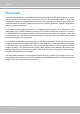
VIVOTEK Overview VIVOTEK FD8362/62E are professional fixed dome network cameras offering 2-Megapixel or 1080p Full HD resolution with superb image quality up to 30 fps� The cameras can capture a much more comprehensive area than a standard VGA model, significantly reducing the number of units required. It is especially suitable for monitoring wide open outdoor such as building entrances, airports or applications requiring accurate identification.
VIVOTEK Read Before Use The use of surveillance devices may be prohibited by law in your country� The Network Camera is not only a high-performance web-ready camera but can also be part of a flexible surveillance system.
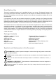
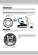
VIVOTEK Physical Description Light Sensor Vari-focal Lens Inner View Black Cover Tilt Adjustment Screw Micro SD/SDHC Card Slot Reset Button Jumpers Microphone Internal Video Output NTSC 60Hz External PAL 50Hz 1 2 Audio/Video Out (green) Microphone In (pink) Ethernet 10/100 RJ45 Socket Heater General I/O Terminal Block NOTE: The heater is only available on FD8362E� Operating environment: -40° ~ 55°C When the temparature inside the Network Camera drops to 0°C, the heater will operate automatic
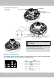
VIVOTEK Outer View IP66-rated Vandal-proof Dome Cover Mounting Plate IMPORTANT! Record the MAC address under the camera base before installing the camera� i INFORMATION: Replace the side opening cover with the included side outlet bushing if you want to route cables from the side of camera� The 1/2" protection conduits and tubing are separately purchased� User's Manual - 7
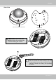
VIVOTEK DI/DO Diagram Please refer to the following illustration for the connection method� 12V PIN 1 Power+12V PIN 2 Digital output +12V PIN 3 Digital input PIN 4 Ground Hardware Reset Reset Button The reset button is used to reset the system or restore the factory default settings� Sometimes resetting the system can return the camera to normal operation� If the system problems remain after reset, press the reset button longer to restore the factory settings and install again� Reset: Press and relea
VIVOTEK Hardware Installation Removing Dome Cover First, use the included T20 hex key wrench to loosen the four screws and detach the dome cover from the camera base� Follow the steps below to install the camera either to a ceiling or a wall� IMPORTANT! Dome cover should be removed because if it should fall during the installation process, physical injury could occur to your co-workers� Top View Dome Cover Dome Cover Retainer Cabling Assembly Connect power lines and if you have external devices such as s
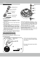
VIVOTEK Waterproof Connector (A) Sealing Nut (A) Housing (B) (B) (D) Seals (C) Seal (D) (E) Screw Nut (E) Hex Nut (F) (F) Assembling Steps 1� D i s a s s e m b l e t h e c o m p o n e n t s o f t h e waterproof connector into parts (A) ~ (F) as shown above� 2� Place the screw nut (E) on the Power and GPIO opening� 3� F e e d t h e p o w e r c a b l e s t h r o u g h t h e waterproof connector (F --> E --> D --> B --> A) as the illustration shows� Then connect the power cables to the power source� Note
VIVOTEK 3� You will need an RJ45 crimping tool to attach the Ethernet wires to a connector� When done, connect the cable to the camera’s Ethernet RJ45 socket � 3 o: white/orange stripe O: orange solid g: white/green stripe B: blue solid b: white/blue stripe G: green solid br: white/brown stripe BR: brown solid o O g B b G br BR 1 2 3 4 5 6 7 8 4� Press the Ethernet cable into the routing path at the bottom of the camera so that the cable will not get in the way when the metal mounting plate is attache
VIVOTEK Wall Mount 1� Attach the supplied alignment sticker to the wall� 2� Using the circle marks on the sticker, drill at least 2 pilot holes symmetrically on each side into the wall� Then hammer the four supplied plastic anchors into the holes� 3� Through three or four holes on the mounting plate, insert the supplied screws into the corresponding holes and secure the mounting plate with a screwdriver� 4� Feed the cables through the triangular cutout A or side opening B� If you want to use hole B, remove
VIVOTEK Network Deployment Setting up the Network Camera over the Internet There are several ways to set up the Network Camera over the Internet� The first way is to set up the Network Camera behind a router� The second way is to utilize a static IP� The third way is to use PPPoE� Internet connection via a router Before enabling the access to the Network Camera over the Internet, make sure you have a router and follow the steps below� 1� Connect your Network Camera behind a router, the Internet environment
VIVOTEK Internet connection with static IP Choose this connection type if you are required to use a static IP for the Network Camera� Please refer to LAN configuration on page 53 for details.
VIVOTEK General Connection (without PoE) 1� If you have external DI devices, make the connection from general I/O terminal block� 2� Ethernet, power, and other cables are user-supplied� Use a Category 5 Cross Cable when Network Camera is directly connected to PC� 3� Connect either the DC or AC pins from the terminal block to a power outlet� Ethernet Switch Pin3 & 4 AC 24V POWER COLLISION 1 2 3 4 5 LINK RECEIVE PARTITION Red Black Pin1 & 2 DC 12V Ethernet Cable User's Manual - 15
VIVOTEK Software Installation Installation Wizard 2 (IW2), free-bundled software included on the product CD, helps you set up your Network Camera on the LAN� 1� Install IW2 under the Software Utility directory from the software CD� Double click the IW2 shortcut on your desktop to launch the program� IW2 Installation Wizard 2 2� The program will conduct an analysis of your network environment� After your network environment is analyzed, please click Next to continue the program� 3� The program will sear
VIVOTEK Ready to Use 1� A browser session with the Network Camera should prompt as shown below� 2� You should be able to see live video from your camera� You may also install the 32-channel recording software from the software CD in a deployment consisting of multiple cameras� For its installation details, please refer to its related documents� User's Manual - 17
VIVOTEK Based on the live image retrieved from the camera, adjust the camera lens to the desired view angle: 1� Loosen the tilt adjustment screws and then turn the lens module up or down� Upon completion, tighten the screw� 2� Turn the lens to adjust the image orientation� Vertical Tilt 80° 1 2 Lens Horzontal Pan 350° Horizontal Pan 350° 3-axis Mechanism Design IMPORTANT: Zoom and Focus adjustment is made via the Remote Focus function on your web browser session with the camera There is no mechanical adj
VIVOTEK Accessing the Network Camera This chapter explains how to access the Network Camera through web browsers, RTSP players, 3GPP-compatible mobile devices, and VIVOTEK recording software� Using Web Browsers Use Installation Wizard 2 (IW2) to access to the Network Cameras on the LAN. If your network environment is not a LAN, follow these steps to access the Netwotk Camera: 1� Launch your web browser (ex� Microsoft® Internet Explorer, Mozilla Firefox, or Netscape). 2.
VIVOTEK NOTE: 1 By default, your Network Camera is not password-protected To prevent unauthorized access, it is highly recommended to configure a password for your camera later.
VIVOTEK Using RTSP Players To view the H�264/MPEG-4 streaming media using RTSP players, you can use one of the following players that support RTSP streaming� Quick Time Player Real Player VLC media player mpegable Player pvPlayer 1� Launch the RTSP player� 2� Choose File > Open URL� A URL dialog box will prompt� 3� The address format is rtsp://:/ As most ISPs and players only allow RTSP streaming through port number 554, please set t
VIVOTEK Using 3GPP-compatible Mobile Devices To view the streaming media through 3GPP-compatible mobile devices, make sure the Network Camera can be accessed over the Internet� For more information on how to set up the Network Camera over the Internet, please refer to Setup the Network Camera over the Internet on page 13� To utilize this feature, please check the following settings on your Network Camera: 1� Because most players on 3GPP mobile phones do not support RTSP authentication, make sure the authen
VIVOTEK Using VIVOTEK Recording Software The product software CD also contains recording software, allowing simultaneous monitoring and video recording for multiple Network Cameras� Please install the recording software; then launch the program to add the Network Camera to the Channel list� For detailed information about how to use the recording software, please refer to the user’s manual of the software or download it from http://www�vivotek�com� User's Manual - 23
VIVOTEK Main Page This chapter explains the screen elements on the main page� It is composed of the following sections: VIVOTEK INC. Logo, Host Name, Camera Control Area, Configuration Area, and Live Video Window� VIVOTEK INC. Logo Click this logo to visit the VIVOTEK website� Host Name The host name can be customized to fit your needs. For more information, please refer to System on page 31.
VIVOTEK Global View: Click on this item to display the Global The viewing region View window� The Global View window contains a full of the current video stream view image (the largest frame size of the captured video) and a floating frame (the viewing region of the current video stream).
VIVOTEK H�264 / MPEG-4 Protocol and Media Options: The transmission protocol and media options for H�264 / MPEG-4 video streaming. For further configuration, please refer to Client Settings on page 28. Time: Display the current time. For further configuration, please refer to Media > Image > Genral settings on page 71� Title and Time: The video title and time can be stamped on the streaming video.
VIVOTEK mode� ■ The following window is displayed when the video mode is set to MJPEG: Video Title Title and Time Video (HTTP-V) 2011/03/10 17:08:56 Time Video 17:08:56 2011/03/10 Video Control Buttons Video Title: The video title can be configured.
VIVOTEK Client Settings This chapter explains how to select the stream transmission mode and saving options on the local computer� When completed with the settings on this page, click Save on the page bottom to enable the settings� H.264 / MPEG-4 Media Options H.264/MPEG-4 Media Options Select to stream video or audio data or both� This is enabled only when the video mode is set to H�264 or MPEG-4� H.264 / MPEG-4 Protocol Options H.
VIVOTEK MP4 Saving Options Users can record live video as they are watching it by clicking page. Here, you can specify the storage destination and file name. Start MP4 Recording on the main Folder: Specify a storage destination for the recorded video files. File name prefix: Enter the text that will be appended to the front of the video file name. Add date and time suffix to the file name: Select this option to append the date and time to the end of the file name.
VIVOTEK Configuration Click Configuration on the main page to enter the camera setting pages� Note that only Administrators can access the configuration page.
VIVOTEK Advanced Mode Navigation Area Configuration List Click to switch to Basic Mode Firmware Version Each function on the configuration list will be explained in the following sections. Those functions that are displayed only in Advanced Mode are marked with Advanced Mode � If you want to set up advanced functions, please click on [Advanced Mode] at the bottom of the configuration list.
VIVOTEK System time Keep current date and time: Select this option to preserve the current date and time of the Network Camera� The Network Camera’s internal real-time clock maintains the date and time even when the power of the system is turned off� Sync with computer time: Select this option to synchronize the date and time of the Network Camera with the local computer� The read-only date and time of the PC is displayed as updated� Manual: The administrator can enter the date and time manually� Note tha
VIVOTEK System > Homepage layout Advanced Mode This section explains how to set up your own customized homepage layout. General settings This column shows the settings of your hompage layout� You can manually select the background and font colors in Theme Options (the second tab on this page)� The settings will be displayed automatically in this Preview field.
VIVOTEK Theme Options Here you can change the color of your homepage layout� There are three types of preset patterns for you to choose from� The new layout will simultaneously appear in the Preview filed.
VIVOTEK ■ Follow the steps below to set up a custome homepage: 1� Click Custom on the left column� 2� Click to select a color on on the right column� Color Selector Custom Pattern 3� The palette window will pop up as shown below� 2 3 1 4 4� Drag the slider bar and click on the left square to select a desired color� 5.
VIVOTEK System > Logs Advanced Mode This section explains how to configure the Network Camera to backup system log to a remote server� Log server settings Follow the steps below to set up the remote log: 1� Select Enable remote log� 2� In the IP address text box, enter the IP address of the remote server� 2� In the port text box, enter the port number of the remote server� 3� When completed, click Save to enable the setting� You can configure the Network Camera to send the system log file to a remote se
VIVOTEK Access log Access log displays the access time and IP address of all viewers (including operators and administrators) in a chronological order� The access log is stored in the Network Camera’s buffer and older events will be overwritten when the number of events reaches a limit� System > Parameters Advanced Mode The View Parameters page lists the entire system’s parameters in an alphabetical order� If you need technical assistance, use a text-editor program to copy and save the parameters listed
VIVOTEK System > Maintenance This chapter explains how to restore the Network Camera to factory default, upgrade firmware version, etc� General settings > Upgrade firmware This feature allows you to upgrade the firmware of your Network Camera� It takes a few minutes to complete the process� Note: Do not power off the Network Camera during the upgrade! Follow the steps below to upgrade the firmware: 1. Download the latest firmware file from the VIVOTEK website. The file is in .pkg file format.
VIVOTEK General settings > Restore This feature allows you to restore the Network Camera to factory default settings� Network: Select this option to retain the Network Type settings (please refer to Network Type on page 53)� Daylight Saving Time: Select this option to retain the Daylight Saving Time settings (please refer to Import/Export files below on this page).
VIVOTEK 3. Open the file with Microsoft® Notepad and locate your time zone; set the start and end time of DST. When completed, save the file. In the example below, DST begins each year at 2:00 a�m� on the second Sunday in March and ends at 2:00 a.m. on the first Sunday in November. Update daylight saving time rules: Click Browse… and specify the XML file to update. If incorrect date and time are assigned, you will see the following warning message when uploading the file to the Network Camera.
VIVOTEK The following message is displayed when attempting to upload an incorrect file format. Export language file: Click to export language strings� VIVOTEK provides nine languages: English, Deutsch, Español, Français, Italiano, 日本語, Português, 簡体中文, and 繁體中文� Update custom language file: Click Browse… and specify your own custom language file to upload. Export configuration file: Click to export all parameters for the device and user-defined scripts.
VIVOTEK Security > User Account This section explains how to enable password protection and create multiple accounts� Root Password The administrator account name is “root”, which is permanent and can not be deleted� If you want to add more accounts in the Manage User column, please apply the password for the “root” account first.
VIVOTEK Advanced Mode Security > HTTPS (Hypertext Transfer Protocol over SSL) This section explains how to enable authentication and encrypted communication over SSL (Secure Socket Layer)� It helps protect streaming data transmission over the Internet on higher security level� Create and Install Certificate Method Before using HTTPS for communication with the Network Camera, a Certificate must be created first.
VIVOTEK 5� Click Home to return to the main page� Change the address from “http://” to “https://“ in the address bar and press Enter on your keyboard� Some Security Alert dialogs will pop up� Click OK or Yes to enable HTTPS� Create self-signed certificate manually 1� Select the second option� 2� Click Create to open the Create Certificate page.
VIVOTEK 3� The following information will show up in a pop-up window after clicking Create� Then click Save to generate the certificate. 4. The Certificate Information will automatically be displayed in the third column as shown below. You can click Property to see detailed information about the certificate.
VIVOTEK 3� If you see the following Information bar, click OK and click on the Information bar at the top of the page to allow pop-ups� 4. The pop-up window shows an example of a certificate request. 5� Look for a trusted certificate authority that issues digital certificates� Enroll the Network Camera� Wait for the certificate authority to issue an SSL certificate; click Browse...
VIVOTEK Click this checkbox to enable HTTPS communication, and then select a connection option from below: "HTTP & HTTPS" or "HTTPS only�" Note that a certificate must have been created and installed before you can click on the "save" button for the configuration to take effect� Tips: ► 1.
VIVOTEK Security > Access List Advanced Mode This section explains how to control access permission by verifying the client PC’s IP address� General Settings Maximum number of concurrent streaming connection(s) limited to: Simultaneous live viewing for 1~10 clients (including stream 1 and stream 2)� The default value is 10� If you modify the value and click Save, all current connections will be disconnected and automatically attempt to re-link (IE Explore or Quick Time Player)� Connection status View I
VIVOTEK ■ Disconnect: If you want to break off the current connections, please select them and click this button� Please note that those checked connections will only be disconnected temporarily and will automatically try to re-link again (IE Explorer or Quick Time Player)� Enable access list filtering: Check this item and click Save if you want to enable the access list filtering function� Filter Filter type: Select Allow or Deny as the filter type.
VIVOTEK Network: This rule allows the user to assign a network address and corresponding subnet mask to the Allow/Deny List. The routing prefix is written in CIDR notation.
VIVOTEK Security > IEEE 802.1x Advanced Mode Enable this function if your network environment uses IEEE 802�1x, which is a port-based network access control� The network devices, intermediary switch/access point/hub, and RADIUS server must support and enable 802�1x settings� The 802�1x standard is designed to enhance the security of local area networks, which provides authentication to network devices (clients) attached to a network port (wired or wireless).
VIVOTEK 3� When all settings are complete, move the Network Camera to the protected LAN by connecting it to an 802�1x enabled switch� The devices will then start the authentication automatically� NOTE: ► The authentication process for 802�1x: 1� The Certificate Authority (CA) provides the required signed certificates to the Network Camera (the supplicant) and the RADIUS Server (the authentication server)� 2� A Network Camera requests access to the protected LAN using 802�1X via a switch (the authenticator
VIVOTEK Network > General settings This section explains how to configure a wired network connection for the Network Camera.
VIVOTEK Primary DNS: The primary domain name server that translates hostnames into IP addresses� Secondary DNS: Secondary domain name server that backups the Primary DNS� Primary WINS server: The primary WINS server that maintains the database of computer name and IP address� Secondary WINS server: The secondary WINS server that maintains the database of computer name and IP address� Enable UPnP presentation: Select this option to enable UPnPTM presentation for your Network Camera so that whenever a Networ
VIVOTEK NOTE: ► If the default ports are already used by other devices connected to the same router, the Network Camera will select other ports for the Network Camera� ► If UPnP TM is not supported by your router, you will see the following message: Error: Router does not support UPnP port forwarding.
VIVOTEK 4� In the Networking Services dialog box, select Universal Plug and Play and click OK� 5� Click Next in the following window� 6� Click Finish� UPnP TM is enabled� ► How does UPnP TM work? UPnP TM networking technology provides automatic IP configuration and dynamic discovery of devices added to a network. Services and capabilities offered by networked devices, such as printing and file sharing, are available among each other without the need for cumbersome network configuration.
VIVOTEK Enable IPv6 Select this option and click Save to enable IPv6 settings� Please note that this only works if your network environment and hardware equipment support IPv6� The browser should be Microsoft® Internet Explorer 6.5, Mozilla Firefox 3.0 or above.
VIVOTEK Please follow the steps below to link to an IPv6 address: 1� Open your web browser� 2� Enter the link-global or link-local IPv6 address in the address bar of your web browser� 3� The format should be: http://[2001:0c08:2500:0002:0202:d1ff:fe04:65f4]/ IPv6 address 4� Press Enter on the keyboard or click Refresh button to refresh the webpage� For example: NOTE: ► If you have a Secondary HTTP port (the default value is 8080), you can also link to the webpage in the following address format: (Please
VIVOTEK Port HTTPS port: By default, the HTTPS port is set to 443� It can also be assigned to another port number between 1025 and 65535� Two way audio port: By default, the two way audio port is set to 5060� Also, it can also be assigned to another port number between 1025 and 65535� The Network Camera supports two way audio communication so that operators can transmit and receive audio simultaneously� By using the Network Camera’s built-in or external microphone and an external speaker, you can communic
VIVOTEK Audio is being transmitted to the Network Camera 2011/03/09 17:08:56 Video (TCP-AV) Mute Talk Button Mic Volume Click to enable audio transmission to the Network Camera; click to turn off the audio� To stop talking, click again� microphone; click to adjust the volume of FTP port: The FTP server allows the user to save recorded video clips. You can utilize VIVOTEK's Installation Wizard 2 to upgrade the firmware via FTP server. By default, the FTP port is set to 21.
VIVOTEK Network > Streaming protocols Advanced Mode HTTP streaming To utilize HTTP authentication, make sure that your have set a password for the Network Camera first; please refer to Security > User account on page 42 for details� Authentication: Depending on your network security requirements, the Network Camera provides two types of security settings for an HTTP transaction: basic and digest� If basic authentication is selected, the password is sent in plain text format and there can be potential r
VIVOTEK URL command -- http://:/ For example, when the Access name for stream 2 is set to video2�mjpg: 1. Launch Mozilla Firefox or Netscape. 2� Type the above URL command in the address bar� Press Enter� 3� The JPEG images will be displayed in your web browser� http://192.168.5.151/video2.
VIVOTEK Authentication: Depending on your network security requirements, the Network Camera provides three types of security settings for streaming via RTSP protocol: disable, basic, and digest� If basic authentication is selected, the password is sent in plain text format, but there can be potential risks of it being intercepted� If digest authentication is selected, user credentials are encrypted using MD5 algorithm, thus providing better protection against unauthorized access.
VIVOTEK Multicast settings for stream 1 ~ 4: Click the items to display the detailed configuration information� Select the Always multicast option to enable multicast for stream 1 ~ 4� Unicast video transmission delivers a stream through point-to-point transmission; multicast, on the other hand, sends a stream to the multicast group address and allows multiple clients to acquire the stream at the same time by requesting a copy from the multicast group address� Therefore, enabling multicast can effectively
VIVOTEK Network > QoS (Quality of Service) Advanced Mode Quality of Service refers to a resource reservation control mechanism, which guarantees a certain quality to different services on the network� Quality of service guarantees are important if the network capacity is insufficient, especially for real-time streaming multimedia applications.
VIVOTEK QoS/DSCP (the DiffServ model) DSCP-ECN defines QoS at Layer 3 (Network Layer)� The Differentiated Services (DiffServ) model is based on packet marking and router queuing disciplines.
VIVOTEK Network > DDNS This section explains how to configure the dynamic domain name service for the Network Camera� DDNS is a service that allows your Network Camera, especially when assigned with a dynamic IP address, to have a fixed host and domain name.
VIVOTEK Manual setup DDNS: Dynamic domain name service Enable DDNS: Select this option to enable the DDNS setting� Provider: Select a DDNS provider from the provider drop-down list� VIVOTEK offers Safe100.net, a free dynamic domain name service, to VIVOTEK customers� It is recommended that you register Safe100.
VIVOTEK 4� Select Enable DDNS and click Save to enable the setting� ■ CustomSafe100 VIVOTEK offers documents to establish a CustomSafe100 DDNS server for distributors and system integrators� You can use CustomSafe100 to register a dynamic domain name if your distributor or system integrators offer such services� 1� In the DDNS column, select CustomSafe100 from the drop-down list� 2.
VIVOTEK Network > SNMP (Simple Network Management Protocol) Advanced Mode This section explains how to use the SNMP on the network camera� The Simple Network Management Protocol is an application layer protocol that facilitates the exchange of management information between network devices� It helps network administrators to remotely manage network devices and find, solve network problems with ease.
VIVOTEK Media > Image Advanced Mode This section explains how to configure the image settings of the Network Camera� It is composed of the following four columns: General settings, Preference, Exposure, and Privacy mask� General settings Timestamp and video title: Enter a name that will be displayed on the title bar of the live video as the picture shown below� Zoom factor: If you check this item, the zoom indicator will be displayed on the Home page when you zoom in/out the live viewing window as the p
VIVOTEK Day/Night Settings Switch to B/W in night mode Select this checkbox to enable the Network Camera to automatically switch to Black & White display during the night mode� IR cut filter With a removable IR-cut filter, this Network Camera can automatically remove the filter to let Infrared light pass into the sensor during low light conditions� ■ Auto mode The Network Camera automatically removes the filter by judging the level of ambient light.
VIVOTEK Preference On this page, you can tune the White balance, Image adjustment and WDR enhanced parameters� You can configure two sets of preferred settings: one for normal situations, the other for special situations, such as day/night/schedule mode� 2011/03/13 17:08:56 Sensor Setting 1: For normal situations Sensor Setting 2: For special situations White balance: Adjust the value for the best color temperature� ■ Auto: It will automatically adjust the color temperature of the light in response to d
VIVOTEK ■ Sharpness: Adjust the image sharpness level, which ranges from -3 to +3� You can also select Customize and manually enter a value� ■ Gamma curve: This function is for user to select a proper gamma curve value to adjust the gray-scale of the monitor� ■ Enable low light compensation: Select this option in low light mode, and the values of sharpness and brightness will change automatically as the noise reduction function� WDR enhanced: This function allows users to identify more image details with a
VIVOTEK If you want to configure another sensor setting for day/night/schedule mode, please click Profile to open the Profile Settings page as shown below.
VIVOTEK Exposure Advanced Mode On this page, you can set the Exposure measurement window, Exposure level, Exposure mode, Exposure time, and Gain control settings� You can configure two sets of Exposure settings: one for normal situations, the other for special situations, such as day/night/schedule mode� 2011/03/13 17:08:56 Sensor Setting 1: For normal situations Sensor Setting 2: For special situations Measurement Window: This function allows users to set measurement window(s) for low light compesatio
VIVOTEK The inclusive window refers to “weighted window“; the exclusive window refers to “ignored window“� It adopts the weighted averages method to calculate the value� Include X 2011/03/13 17:08:56 Weighted region Ignored region Exclude X 2011/03/13 17:08:56 ■ BLC (Back Light Compensation): This option will automatically add a “weighted region“ in the middle of the window and give the necessary light compensation� Exposure control: ■ Exposure level: You can manually set the Exposure level, which ran
VIVOTEK Auto: If you set Exposure mode as Auto, the Exposure time and Gain control will be not configurable since the sensor library will automatically adjust the value according to the ambient light� Then you can set iris mode as "indoor" or "outdoor" to reach the best image quality� You can click Preview to fine-tune the image, or click Restore to recall the original settings without incorporating the changes� When completed with the settings on this page, click Save to enable the settings� If you want
VIVOTEK Focus Focus, also known as Remote Focus, is applicable to Network Cameras that are equipped with stepping motor lens� The automated focus adjustment function eliminates the needs to physically adjust camera focus� In an outdoor deployment consisting of a large number of cameras, the auto focus function can be very helpful when these cameras become out of focus after days or weeks of operation� And that can easily result from the effects of natural forces, e�g�, shrink and expand due to a wide range
Privacy mask Advanced Mode Click Privacy Mask to open the settings page. On this page, you can block out certain sensitive zones to address privacy concerns� 2011/03/15 17:08:56 ■ To set the privacy mask windows, follow the steps below: 1� Click New to add a new window� 2.
VIVOTEK Media > Video Stream settings Advanced Mode Enable time shift caching stream: Select one stream as the time shift cache stream� This function enable the time shift cache stream on the Network Camera, which will store video in the camera’s embedded memory for a period of time depending on the cache memory on each Network Camera� This function can work seamlessly with VIVOTEK’s ST7501 recording software� When an event occurs, the recording software can request time shift cache stream from the camer
VIVOTEK NOTE: ► All the items in the “Region of Interest” cannot be greater than the “Output Frame Size“ (current maximum resolution)� ■ The parameters of the multiple streams: Stream 1 Stream 2 Stream 3 Stream 4 Region of Interest Output frame size 1920 X 1080 ~ 176 x 144 (Selectable) 1920 X 1080 ~ 176 x 144 (Selectable) 1920 X 1080 ~ 176 x 144 (Selectable) 1920 X 1080 (Fixed) 1920 X 1080 ~ 176 x 144 (Selectable) 1920 X 1080 ~ 176 x 144 (Selectable) 1920 X 1080 ~ 176 x 144 (Selectable) 1920 X 1080 ~ 1
VIVOTEK Click the stream item to display the detailed information. The maximum frame size will follow your settings in the above Viewing window sections� This Network Camera offers real-time H�264, MPEG-4 and MJPEG compression standards (Triple Codec) for real-time viewing� If H.
VIVOTEK ■ Intra frame period Determine how often to plant an I frame� The shorter the duration, the more likely you will get better video quality, but at the cost of higher network bandwidth consumption� Select the intra frame period from the following durations: 1/4 second, 1/2 second, 1 second, 2 seconds, 3 seconds, and 4 seconds� ■ Video quality A complex scene generally produces a larger file size, meaning that higher bandwidth will be needed for data transmission� Therefore, if Constant bit rate is se
VIVOTEK Media > Audio Audio Settings Mute: Select this option to disable audio transmission from the Network Camera to all clients� Note that if mute mode is turned on, no audio data will be transmitted even if audio transmission is enabled on the Client Settings page� In that case, the following message is displayed: Internal microphone input gain: Select the gain of the external audio input according to ambient conditions� Adjust the gain from +21 db (most sensitive) or -33 db (least sensitive)� Extern
VIVOTEK PTZ > PTZ settings Advanced Mode This section explains how to control the Network Camera’s Pan/Tilt/Zoom operation� Digital: Control the e-PTZ operation� It allows users to quickly move the focus to a preconfigured target area for close-up viewing without physically zooming the camera.
VIVOTEK Home page in E-PTZ Mode 2011/03/10 17:08:56 x1.
VIVOTEK Patrol settings You can select some preset positions for the Network Camera to patrol� Please follow the steps below to set up a patrol schedule: 1� Select the preset locations on the list, and click � 2� The selected preset locations will be displayed on the Patrol locations list� 3� Set the Dwelling time for the streaming view to stay at the preset location during auto patrol� 4� If you want to delete a preset location from the Patrol locations list, select it and click Remove� 5� Select a locati
VIVOTEK Event > Event settings Advanced Mode This section explains how to configure the Network Camera to respond to particular situations (event)� A typical application is that when a motion is detected, the Network Camera sends buffered images to an FTP server or e-mail address as notifications� Click on Help, there is an illustration shown in the pop-up window explaining that an event can be triggered by many sources, such as motion detection or external digital input devices� When an event is trigger
VIVOTEK ■ Event name: Enter a name for the event setting� ■ Enable this event: Select this option to enable the event setting� ■ Priority: Select the relative importance of this event (High, Normal, or Low)� Events with a higher priority setting will be executed first.
VIVOTEK ■ Camera tampering detection This option allows the Network Camera to trigger when the camera detects that is is being tampered with� To enable this function, you need to configure the Tampering Detection option first. Please refer to page 105 for detailed information� ■ Manual Trigger This option allows user to enable event triggers manually by clicking the on/off button on the homepage. Please configure 1 ~ 3 events before using this function.
VIVOTEK To configure an event with video recording or snapshots, it is necessary to configure/provide servers and storage media settings so that the Network Camera will know where to send the media files to when a trigger is activated� Add server Click Add server to unfold the server setting window. You can specify where the notification messages are sent when a trigger is activated. A total of 5 server settings can be configured.
VIVOTEK To verify if the email settings are correctly configured, click Test� The result will be shown in a pop-up window� If successful, you will also receive an email indicating the result� Click Save server to enable the settings, then click Close to exit the Add server page� After you set up the first event server, a new item for event server will automatically appear on the Server list� If you wish to add more server options, click Add server� Server type - FTP Select to send the media files to an F
VIVOTEK ■ Passive mode Most firewalls do not accept new connections initiated from external requests� If the FTP server supports passive mode, select this option to enable passive mode FTP and allow data transmission to pass through the firewall. To verify if the FTP settings are correctly configured, click Test� The result will be shown in a pop-up window as shown below. If successful, you will also receive a test.txt file on the FTP server.
VIVOTEK Network storage: Select to send the media files to a network storage location when a trigger is activated� Please refer to NAS server on page 108 for details� Click Save server to enable the settings, then click Close to exit the Add server page� ■ SD Test: Click to test your SD card. The system will display a message indicating success or failure.
VIVOTEK Add media Click Add media to open the media setting window� You can specify the type of media that will be sent when a trigger is activated. A total of 5 media settings can be configured. There are three choices of media types available: Snapshot, Video Clip, and System log� Select the item to display the detailed configuration options. You can configure either one or all of them.
VIVOTEK ■ Add date and time suffix to the file name Select this option to add a date/time suffix to the file name.
VIVOTEK ■ Maximum duration Specify the maximum recording duration in seconds� Up to 10 seconds of video can be recorded� For example, if pre-event recording is set to 5 seconds and the maximum duration is set to 10 seconds, the Network Camera continues to record for another 4 seconds after a trigger is activated� 1 sec. 2 sec. 3 sec. 4 sec. 5 sec. 6 sec. 7 sec. 8 sec. 9 sec. 10 sec. Trigger Activation ■ Maximum file size Specify the maximum file size allowed.
VIVOTEK ■ View: Click this button to open a file list window. This function is only for SD card and Network Storage.
VIVOTEK Here is an example of the Event setting: When completed the settings with steps 1~3 to arrange Schedule, Trigger, and Action of an event, click Save event to enable the settings and click Close to exit the page� The following is an example of the Event setting page: 100 - User's Manual
VIVOTEK When the Event Status is ON, once an event is triggered by motion detection, the Network Camera will automatically send snapshots via e-mail� If you want to stop the event trigger, you can click ON to turn it to OFF status or click Delete to remove a previously-configured event setting.
VIVOTEK Applications > Motion detection This section explains how to configure the Network Camera to enable motion detection. A total of three motion detection windows can be configured.
VIVOTEK A green bar indicates that even though motions have been detected, the event has not been triggered because the image variations still fall under the defined threshold. Percentage = 30% If you want to configure specific motion detection settings individually for day/night/schedule operations, please click Profile to open the Motion Detection Profile Settings page as shown below. A total of three motion detection windows can be configured on this page as well.
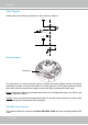
VIVOTEK NOTE: ► How does motion detection work? A C B D There are two motion detection parameters: Sensitivity and Percentage� In the illustration above, frame A and frame B are two sequential images� Pixel differences between the two frames are detected and highlighted in gray (frame C) and will be compared with the sensitivity setting� Sensitivity is a value that expresses the sensitivity to moving objects� Higher sensitivity settings are expected to detect slight movements while smaller sensitivity
VIVOTEK Applications > DI and DO Advanced Mode Digital input: Select High or Low to define the activate status for the digital input. The Network Camera's current status is shown on the right� Digital output: Select Grounded or Open to define normal status for the digital output� The Network Camera will show whether the trigger is activated or not� Set up the event source as DI on Event > Event settings > Trigger.
VIVOTEK Recording > Recording settings Advanced Mode This section explains how to configure the recording settings for the Network Camera. Recording Settings Insert your SD card and click here to test NOTE: Please remember to format your SD card when used for the first time. Please refer to page 111 for detailed information� Recording Settings Click Add to open the recording setting window.
VIVOTEK If you enable adaptive recording and enable time-shift cache stream on Camera A, only when an event is triggered on Camera A will the server record the streaming data in full frame rate; otherwise, it will only request the I frame data during normal monitoring, thus effectively save lots of bandwidths and storage� NOTE: ► To enable adaptive recording, please make sure you’ve set up the trigger sources such as Motion Detection, DI Device, or Manual Trigger� Bandwidth I frame ---> Full frame rate -
VIVOTEK 2� Destination You can select the SD card or network storage (NAS) for the recorded video files.
VIVOTEK If successful, you will receive a test.txt file on the networked storage server. 3� Enter a server name� 4� Click Save to complete the settings and click Close to exit the page� ■ Capacity: You can either choose the entire available space or impose a reserved space.
VIVOTEK card� The new recording name will appear on the recording page as shown below� To remove an existing recording setting from the list, single-click to select it and click Delete� ■ Video (Name): Click to open the Recording settings page to modify� ■ ON (Status): Click to manually adjust the Status� (ON: start recording; OFF: stop recording) ■ NAS or SD (Destination): Click to open the file list of recordings as shown below.
VIVOTEK Local storage > SD card management This section explains how to manage the local storage on the Network Camera� Here you can view SD card status, and implement SD card control� SD card staus This column shows the status and reserved space of your SD card� Please remember to format the SD card when using for the first time.
VIVOTEK Local storage > Content management This section explains how to manage the content of recorded videos on the Network Camera� Here you can search and view the records and view the searched results� Searching and Viewing the Records This column allows the user to set up search criteria for recorded data� If you do not select any criteria and click Search button, all recorded data will be listed in the Search Results cloumn� ■ File attributes: Select one or more items as your search criteria.
VIVOTEK ■ View: Click on a search result which will highlight the selected item in purple as shown above. Click the View button and a media window will pop up to play back the selected file. For example: Click to adjust the image size ■ Download: Click on a search result to highlight the selected item in purple as shown above. Then click the Download button and a file download window will pop up for you to save the file. ■ JPEGs to AVI: This function only applies to “JPEG“ format files such as snapshots.
VIVOTEK Appendix URL Commands for the Network Camera 1.
VIVOTEK 2. Style Convention In URL syntax and in descriptions of CGI parameters, a text within angle brackets denotes a content that is to be replaced with either a value or a string. When replacing the text string, the angle brackets shall also be replaced. An example of this is the description of the name for the server, denoted with in the URL syntax description below, which is replaced with the string myserver in the URL syntax example, also below.
VIVOTEK http://mywebserver/cgi-bin/dido/setdo.cgi?do1=1 4. Security Level SECURITY SUB-DIRECTORY DESCRIPTION 0 anonymous Unprotected. 1 [view] anonymous, viewer, 1. Can view, listen, talk to camera. LEVEL dido, camctrl 4 [operator] 6 [admin] 2. Can control DI/DO, PTZ of the camera. anonymous, viewer, Operator access rights can modify most of the camera‟s dido, camctrl, operator parameters except some privileges and network options.
VIVOTEK When querying parameter values, the current parameter values are returned. A successful control request returns parameter pairs as follows: Return: HTTP/1.0 200 OK\r\n Content-Type: text/html\r\n Context-Length: \r\n \r\n where is =\r\n [] is the actual length of content. Example: Request IP address and its response Request: http://192.168.0.123/cgi-bin/admin/getparam.cgi?network_ipaddress Response: HTTP/1.
VIVOTEK http:///cgi-bin/admin/setparam.cgi? = [&=…][&update=] [&return=] PARAMETER VALUE DESCRIPTION _ value to assigned Assign to the parameter _. update Set to 1 to update all fields (no need to update parameter in each group). return Redirect to the page after the parameter is assigned.
VIVOTEK 7. Available parameters on the server Valid values: VALID VALUES DESCRIPTION string[] Text strings shorter than „n‟ characters. The characters “,‟, <,>,& are invalid. string[n~m] Text strings longer than `n‟ characters and shorter than `m‟ characters. The characters “,‟, <,>,& are invalid. password[] The same as string but displays „*‟ instead. integer Any number between (-231 – 1) and (231 – 1). positive integer Any number between 0 and (232 – 1).
VIVOTEK 7.1 system Group: system NAME VALUE DEFAULT SECURITY DESCRIPTION (get/set) hostname string[40] Mega-Pixe 1/6 Host name of server l Network (Network Camera, Camera Wireless Network Camera, Video Server, Wireless Video Server). lowlight Turn on white light LED under all conditions. Only turn on white light LED in low light conditions. (product dependent) date , time 6/6 date> Current date of system. Set to „keep‟ to keep date keep, unchanged.
VIVOTEK -360: GMT-09:00 Alaska -320: GMT-08:00 Las Vegas, San_Francisco, Vancouver -280: GMT-07:00 Mountain Time, Denver -281: GMT-07:00 Arizona -240: GMT-06:00 Central America, Central Time, Mexico City, Saskatchewan -200: GMT-05:00 Eastern Time, New York, Toronto -201: GMT-05:00 Bogota, Lima, Quito, Indiana -180: GMT-04:30 Caracas -160: GMT-04:00 Atlantic Time, Canada, La Paz, Santiago -140: GMT-03:30 Newfoundland -120: GMT-03:00 Brasilia, Buenos Aires, Georgetown, Greenland -80: GMT-02:00 Mid-Atlantic -
VIVOTEK 83: GMT 02:00 Israel 120: GMT 03:00 Baghdad, Kuwait, Riyadh, Moscow, St.
VIVOTEK > daylight_dstactualmode saving time in time zone. Check if current time is under daylight saving time. (Used internally) daylight_auto_begintime string[19] NONE 6/7 Display the current daylight saving start time. daylight_auto_endtime string[19] NONE 6/7 Display the current daylight saving end time. daylight_timezones string ,-360,-32 6/6 0, List time zone index which support daylight saving time.
VIVOTEK This command can cooperate with other “restoreexceptXYZ” commands. When cooperating with others, the system parameters will be restored to the default value except for a union of the combined results. restoreexceptdst Restore the system parameters to default values except all daylight saving time settings. This command can cooperate with other “restoreexceptXYZ” commands.
VIVOTEK 7.1.1 system.info Subgroup of system: info (The fields in this group are unchangeable.) NAME VALUE DEFAULT SECURITY DESCRIPTION (get/set) modelname string[40] FD8362E 0/7 Internal model name of the server (e.g., IP7139) extendedmodelname string[40] FD8362E 0/7 ODM specific model name of server (e.g., DCS-5610). If it is not an ODM model, this field will be equal to “modelname” serialnumber
VIVOTEK 7.2 status Group: status NAME VALUE DEFAULT SECURITY DESCRIPTION (get/set) videoactualmodulation ntsc, pal 1 4/7 The actual modulation type (videoin.type=0). di_i<0~(ndi-1)> 0 1/7 0 => Inactive, normal 1 => Active, triggered (capability.ndi > 0) do_i<0~(ndo-1)> 0 1/7 0 => Inactive, normal 1 => Active, triggered (capability.
VIVOTEK 7.4 digital output behavior define Group: do_i<0~(ndo-1)> (capability.ndo > 0) NAME VALUE DEFAULT SECURITY DESCRIPTION (get/set) normalstate open, open 1/1 grounded Indicate open circuit or closed circuit (inactive status) 7.5 security Group: security NAME VALUE DEFAULT SECURITY DESCRIPTION (get/set) privilege_do view, operator, operator 6/6 admin Indicate which privileges and above can control digital output (capability.
VIVOTEK ss integer> as follows: Bit 0 => HTTP service; Bit 1=> HTTPS service; Bit 2=> FTP service; Bit 3 => Two way audio and RTSP Streaming service; To stop service before changing its port settings. It‟s recommended to set this parameter when change a service port to the port occupied by another service currently. Otherwise, the service may fail. Stopped service will auto-start after changing port settings. Ex: Change HTTP port from 80 to 5556, and change RTP port for video from 5556 to 20480.
VIVOTEK wins1 6/6 Primary WINS server. 6/6 Secondary WINS server. address> wins2 7.6.1 802.1x Subgroup of network: ieee8021x (capability.protocol.ieee8021x > 0) NAME VALUE DEFAULT SECURITY DESCRIPTION (get/set) enable eapmethod 0 6/6 Enable/disable IEEE 802.
VIVOTEK vlanid 1~4095 1 6/6 VLAN ID video 0~7 0 6/6 Video channel for CoS audio 0~7 0 6/6 Audio channel for CoS 0) dependent> eventalarm 0~7 0 6/6 Event/alarm channel for CoS management 0~7 0 6/6 Management channel for CoS eventtunnel 0~7 0 6/6 Event/Control channel for CoS Subgroup of network: qos_dscp (capability.protocol.qos.
VIVOTEK 7.6.3 IPV6 Subgroup of network: ipv6 (capability.protocol.ipv6 > 0) NAME VALUE DEFAULT SECURITY DESCRIPTION (get/set) enable 0 6/6 Enable IPv6. addonipaddress 6/6 IPv6 IP address. addonprefixlen 0~128 64 6/6 IPv6 prefix length. addonrouter 6/6 IPv6 router address. addondns 6/6 IPv6 DNS address. allowoptional 0 6/6 Allow manually setup of IP address setting. 7.6.
VIVOTEK dependent> (capability.protocol.spush_mjpeg =1 and capability.nmediastream > 1) s2_accessname string[32] video3.mjpg 1/6 (capability.protocol.spush_mjpeg =1 and capability.nmediastream > 2) s3_accessname string[32] video4.mjpg 1/6 (capability.protocol.spush_mjpeg =1 and capability.nmediastream > 3) s4_accessname string[32] videoany.
VIVOTEK 7.6.7 RTSP Subgroup of network: rtsp (capability.protocol.rtsp > 0) NAME VALUE DEFAULT SECURITY DESCRIPTION (get/set) port 554, 1025 ~ 554 1/6 65535 anonymousviewing RTSP port. (capability.protocol.rtsp=1) 0 1/6 Enable anoymous streaming viewing. authmode disable, disable 1/6 basic, RTSP authentication mode. (capability.protocol.rtsp=1) digest s0_accessname live.sdp 1/6 RTSP access name for stream1. (capability.protocol.rtsp=1 and capability.
VIVOTEK for anystream. (capability.protocol.rtsp=1 and capability.nanystream = 1) s0_audiotrack 0 1/6 Enable audio for stream1. s1_audiotrack 0 1/6 Enable audio for stream2. s2_audiotrack 0 1/6 Enable audio for stream3. s3_audiotrack 0 1/6 Enable audio for stream4. S4_audiotrack 0 1/6 Enable audio for stream5. 7.6.7.1 RTSP multicast Subgroup of network_rtsp_s<0~(n-1)>: multicast, n is stream count (capability.protocol.rtp.
VIVOTEK 7.6.9 RTP port Subgroup of network: rtp NAME VALUE DEFAULT SECURITY DESCRIPTION (get/set) videoport 1025 ~ 65535 5556 6/6 Video channel port for RTP. (capability.protocol.rtp_unicast=1) audioport 1025 ~ 65535 5558 6/6 Audio channel port for RTP. (capability.protocol.rtp_unicast=1) 7.6.10 PPPoE Subgroup of network: pppoe (capability.protocol.pppoe > 0) NAME VALUE DEFAULT SECURITY DESCRIPTION (get/set) user string[128] 6/6 PPPoE account user name.
VIVOTEK address / network mask> Range address: ipv6list_i<0~9> String[44] 6/6 IPv6 address list. 7.8 Video input Group: videoin NAME VALUE DEFAULT SECURITY DESCRIPTION (get/set) cmosfreq 50, 60 60 4/4 CMOS frequency. (capability.videoin.type=2) whitebalance auto, manual auto 4/4 “auto” indicates auto white balance. “manual” indicates keep current value. exposurelevel 0~12 6 4/4 Exposure level autoiris 0 4/4 Enable auto Iris.
VIVOTEK ptzstatus 2 1/7 A 32-bit integer, each bit can be set separately as follows: Bit 0 => Support camera control function; 0(not support), 1(support) Bit 1 => Built-in or external camera; 0 (external), 1(built-in) Bit 2 => Support pan operation; 0(not support), 1(support) Bit 3 => Support tilt operation; 0(not support), 1(support) Bit 4 => Support zoom operation; 0(not support), 1(support) Bit 5 => Support focus operation; 0(not support), 1(support) text string[16] 1/
VIVOTEK NAME VALUE DEFAULT SECURITY DESCRIPTION (get/set) cmosfreq 50, 60 60 4/4 CMOS frequency. (capability.videoin.type=2) whitebalance auto, manual auto 4/4 “auto” indicates auto white balance. “manual” indicates keep current value. rgain 0~100 30 4/4 Manual set rgain value of gain control setting. bgain 0~100 30 4/4 Manual set bgain value of gain control setting.
VIVOTEK imprinttimestamp 0 4/4 Overlay time stamp on video. exposuremode auto,fixed auto 4/4 Exposure mode maxexposure 1~32000 32000 4/4 Maximum exposure time. maxexposure 1~32000 30 4/4 Maximum exposure time. options quality, quality 4/4 Video input option: framerate, crop (1) video quality first mode (2) video frame rate first mode (3) cropping mode (not used in FD8362E) preoptions quality, quality 4/4 framerate, crop Record the previous video options.
VIVOTEK 99, 100 choosing vbr in “ratecontrolmode”. 99 is the customized manual input setting. 1 = worst quality, 5 = best quality. 100 is percentage mode. s<0~(m-1)>_mpeg4_qvalu 2~31 7 4/4 e Manual video quality level input. (s<0~(m-1)>_mpeg4_qua nt = 99) s<0~(m-1)>_mpeg4_qperc 1~100 29 4/4 ent Manual video quality level input. (s<0~(m-1)>_mpeg4_qua nt = 100) s<0~(m-1)>_mpeg4_bitrat e 1000~160000 51200 4/4 00 Set bit rate in bps when choosing cbr in
VIVOTEK = 99) s<0~(m-1)>_h264_qperce 1~100 44 4/4 nt Manual video quality level input. (s<0~(m-1)>_h264_quant = 100) s<0~(m-1)>_h264_bitrate 1000~160000 30000000 4/4 00 Set bit rate in bps when choosing cbr in “ratecontrolmode”. s<0~(m-1)>_h264_maxfra me 1~25, 30 1/4 26~30 (only Set maximum frame rate in fps (for h264).
VIVOTEK indoor and outdoor mode. piris_position 1~100 12 1/4 P-Iris position for manual mode. wdrc_mode 0~3 0 4/4 WDR enhanced. 0: off 1: auto 2: always on 3: keep current value wdrc_strength 0~2 1 4/4 WDR enhanced. 0: low 1: medium 2: high 7.8.1.1 Alternative video input profiles per channel In addition to the primary setting of video input, there can be alternative profile video input setting for each channel which might be for different scene of light (daytime or nighttime).
VIVOTEK maxgain 0~100 100 4/4 Manual set maximum gain value. mingain 0~100 0 4/4 Manual set minimum gain value. autoiris 0 4/4 Enable auto Iris. (not used in FD8362E) enablewdr 0 4/4 Enable/disable wield dynamic range. (not used in FD8362E) whitebalance auto, manual manual 4/4 “auto” indicates auto white balance. “manual” indicates keep current value. rgain 0~100 52 4/4 bgain 0~100 47 4/4 Manual set rgain value of gain control setting.
VIVOTEK 7.9 Video input preview The temporary settings for video preview Group: videoinpreview NAME VALUE DEFAULT SECURITY DESCRIPTION (get/set) exposuremode auto,fixed auto 4/4 Exposure Mode minexposure 1~32000 32000 4/4 Minimum exposure time. maxexposure 1~32000 30 4/4 Maximum exposure time. exposurelevel 0~12 6 4/4 Exposure level enableblc 0 4/4 Enable backlight compensation. enablewdr 0 4/4 Enable/disable wield dynamic range.
VIVOTEK maxgain 0~100 100 4/4 Manual set maximum gain value. mingain 0~100 0 4/4 Manual set minimum gain value. autoiris 0 4/4 Enable auto Iris. (not used in FD8362E) 7.10 IR cut control Group: ircutcontrol (capability.
VIVOTEK saturationpercent 0~100 50 4/4 Adjust saturation value of percentage when saturation=100 contrast -5 ~ 5 0 4/4 Adjust contrast of image according to mode settings. sharpness -3~3,100 0 4/4 Adjust sharpness of image according to mode settings. sharpnesspercent 0~100 50 4/4 Adjust sharpness value of percentage when sharpness=100 gammacurve 0~100 0 4/4 Gamma curve. lowlightmode 1 4/4 Enable/disable low light mode.
VIVOTEK 7.12 Image setting for preview Group: imagepreview_c<0~(n-1)> for n channel products NAME VALUE DEFAULT SECURITY DESCRIPTION (get/set) brightness -5~5 -5 4/4 Adjust brightness of image according to mode settings. saturation -5~5,100 0 4/4 Adjust saturation of image according to mode settings. 100 for saturation percentage mode.
VIVOTEK 7.13 Exposure window setting per channel Group: exposure_c<0~(n-1)> for n channel products NAME VALUE DEFAULT SECURITY DESCRIPTION (get/set) mode auto, custom, auto 4/4 The mode indicates how to blc decide the exposure. auto: Use full view as the only one exposure window. custom: Use inclusive and exclusive window. blc: Use BLC. win_i<0~9>_enable 0 4/4 Enable or disable the window. win_i<0~9>_policy 0~1 0 4/4 0: Indicate exclusive. 1: Indicate inclusive.
VIVOTEK 7.14 Audio input per channel Group: audioin_c<0~(n-1)> for n channel products (capability.audioin>0) NAME VALUE DEFAULT SECURITY DESCRIPTION (get/set) source linein linein 4/4 micin => use built-in microphone input. linein => use external microphone input. mute 0, 1 0 4/4 Enable audio mute. gain 9~108 69 4/4 Gain of input. (audioin_c<0~(n-1)>_source = linein) boostmic 9~108 69 4/4 Enable microphone boost. 0 => +0dB 1 => +20dB 2 => +40dB Or Gain of input.
VIVOTEK 7.15 Time Shift settings Group: timeshift, c for n channel products, m is stream number (capability.timeshift > 0) NAME VALUE DEFAUL T SECURITY DESCRIPTION (get/set) enable 0 4/4 Enable time shift streaming. c<0~(n-1)>_s<0 0 4/4 Enable time shift streaming for ~(m-1)>_allow specific stream. 7.
VIVOTEK i<0~(m-1)>_begintime hh:mm 18:00 4/4 Begin time of schedule mode. i<0~(m-1)>_endtime hh:mm 06:00 4/4 End time of schedule mode. i<0~(m-1)>_win_i<0~2>_enable 0 4/4 Enable motion window. i<0~(m-1)>_win_i<0~2>_name string[14] 4/4 Name of motion window. i<0~(m-1)>_win_i<0~2>_left 0 ~ 320 0 4/4 Left coordinate of window position. i<0~(m-1)>_win_i<0~2>_top 0 ~ 240 0 4/4 Top coordinate of window position.
VIVOTEK more than „duration‟ second(s), then tamper detection is triggered. 7.18 DDNS Group: ddns (capability.ddns > 0) NAME VALUE DEFAULT SECURITY DESCRIPTION (get/set) enable provider Safe100, DyndnsDynamic, DyndnsCustom, TZO, DHS, 6/6 Enable or disable the dynamic DNS. DyndnsDy 6/6 Safe100 => safe100.net namic DyndnsDynamic => dyndns.org (dynamic) DyndnsCustom => dyndns.org (custom) DynInterfree, TZO => tzo.com CustomSafe100, DHS => dhs.
VIVOTEK HUAGAI, PCCW => pccw.com 3322, MegaChips => megachips.co.jp ALARM, Dlink =>D-LINK ChangeIP, DlinkCN => D-LINK CN NOIP Logitec => logitec.co.jp SWISSCOM GE_Security =>GE Security CustomizedTZO HUAGAI => huagai.com 3322.net dependent> ALARM => alarm.com ChangeIP => TOSHIBA NOIP => TOSHIBA SWISSCOM =>swiss.com CustomizedTZO => Customized server using TZO method _h string[128] 6/6 Your DDNS hostname.
VIVOTEK 7.20 UPnP presentation Group: upnppresentation NAME VALUE DEFAULT SECURITY DESCRIPTION (get/set) enable 1 6/6 Enable or disable the UPnP presentation service. 7.21 UPnP port forwarding Group: upnpportforwarding NAME VALUE DEFAULT SECURITY DESCRIPTION (get/set) enable 0 6/6 Enable or disable the UPnP port forwarding service. upnpnatstatus 0~3 0 6/7 The status of UPnP port forwarding, used internally.
VIVOTEK 6: LOG_INFO 7: LOG_DEBUG setparamlevel 0~2 0 6/6 Show log of parameter setting. 0: disable 1: Show log of parameter setting set from external. 2. Show log of parameter setting set from external and internal. 7.23 SNMP Group: snmp (capability.snmp > 0) NAME VALUE DEFAULT SECURITY DESCRIPTION (get/set) v2 0~1 0 6/6 SNMP v2 enabled. 0 for disable, 1 for enable v3 0~1 0 6/6 SNMP v3 enabled.
VIVOTEK 7.24 Layout configuration Group: layout (New version) NAME VALUE DEFAULT SECURITY DESCRIPTION (get/set) logo_default logo_link string[40] 0 => Custom logo 1 => Default logo http://ww 1/6 Hyperlink of the logo 1/6 0 => display the power by w.vivotek.
VIVOTEK 7.25 Privacy mask Group: privacymask_c<0~(n-1)> for n channel product NAME VALUE DEFAULT SECURITY DESCRIPTION (get/set) enable 0 4/4 Enable privacy mask. win_i<0~4>_enabl 0 4/4 Enable privacy mask e win_i<0~4>_name window. string[14] 4/4 Name of the privacy mask window. win_i<0~4>_left 0 ~ 320/352 0 4/4 Left coordinate of window position. win_i<0~4>_top 0 ~ 240/288 0 4/4 Top coordinate of window position.
VIVOTEK nvi 0, 3 0/7 ndo 0, 1 0/7 Number of digital outputs. 1 0/7 Number of audio inputs. 1 0/7 Number of audio outputs. 1 0/7 Number of video inputs. 4 0/7 Number of media stream naudioin 0, naudioout 0, nvideoin nmediastream nvideosetting naudiosetting
VIVOTEK Bit 3 => Support tilt operation; 0(not support), 1(support) Bit 4 => Support zoom operation; 0(not support), 1(support) Bit 5 => Support focus operation; 0(not support), 1(support) Bit 6 => Support iris operation; 0(not support), 1(support) Bit 7 => External or built-in PT; 0(built-in), 1(external) Bit 8 => Invalidate bit 1 ~ 7; 0(bit 1 ~ 7 are valid), 1(bit 1 ~ 7 are invalid) Bit 9 => Reserved bit; Invalidate lens_pan, Lens_tilt, lens_zoon, lens_focus, len_iris.
VIVOTEK support SIP. protocol_maxconnection protocol_maxgenconnection protocol_maxmegaconnectio n protocol_rtp_multicast_ The maximum allowed Indicate whether to support scalable multicast.
VIVOTEK dependent> videoin_codec mpeg4. mjpeg, h264 0/7 Available codec list. 0 0/7 mjpeg, h264 dependent> videoout_codec audio_aec Indicate whether to support acoustic echo cancellation. audio_extmic 1 0/7 Indicate whether to support external microphone input.
VIVOTEK of PTZ control in the Security page. 1: support both /cgi-bin/camctrl/camctrl.cgi and /cgi-bin/viewer/camctrl.cgi 0: support only /cgi-bin/viewer/camctrl.cgi uart_httptunnel 0 0/7 Indicate whether to support HTTP tunnel for UART transfer. transmission_mode Tx, Tx 0/7 Indicate transmission Rx, mode of the machine: TX = Both server, Rx = receiver box, Both = DVR. network_wire 1 0/7 Indicate whether to support Ethernet.
VIVOTEK VVXX. (TCVV<->TCXX is excepted) npreset 0, eptz 0, can be set separately as follows: Bit 0 => stream 1 supports ePTZ or not. Bit 1 => stream 2 supports ePTZ or not.
VIVOTEK time string[17] 6/7 Time of custom script. Default SECURITY DESCRIPTION 7.28 Event setting Group: event_i<0~2> PARAMETER VALUE (get/set) name string[40] 6/6 Identification of this entry. enable 0, 1 0 6/6 Enable or disable this event. priority 0, 1, 2 1 6/6 Indicate the priority of this event: “0” = low priority “1” = normal priority “2” = high priority delay 1~999 20 6/6 Delay in seconds before detecting the next event.
VIVOTEK mdwin0 0 6/6 Similar to mdwin. The parameter takes effect when profile 1 of motion detection is enabled. vi 0 6/6 Indicate the source id of vi trigger. This field is required when trigger condition is “vi”. One bit represents one digital input. The LSB indicates VI 0. inter 1~999 1 6/6 Interval of snapshots in minutes. This field is used when trigger condition is “seq”. weekday 0~127 127 6/6 Indicate which weekday is scheduled. One bit represents one weekday.
VIVOTEK action_goto_name string[40] 6/6 action_cf_enable Specify the preset name that ptz goto on event triggered. 0 6/6 Enable or disable sending media to SD card. action_cf_folder string[128] 6/6 Path to store media. action_cf_media NULL, 0~4 6/6 Index of the attached media. action_cf_datefolder 0 6/6 Enable this to create folders by date, time, and hour automatically.
VIVOTEK 7.29 Server setting for event action Group: server_i<0~4> PARAMETER VALUE DEFAULT SECURITY DESCRIPTION (get/set) name string[40] NULL 6/6 Identification of this entry type email, email 6/6 Indicate the server type: ftp, “email” = email server http, “ftp” = FTP server ns “http” = HTTP server “ns” = network storage http_url string[128] http:// 6/6 URL of the HTTP server to upload. http_username string[64] NULL 6/6 Username to log in to the server.
VIVOTEK 7.30 Media setting for event action Group: media_i<0~4> (media_freespace is used internally.) PARAMETER VALUE DEFAULT SECURITY DESCRIPTION (get/set) name string[40] NULL 6/6 type snapshot, snapshot 6/6 systemlog, Identification of this entry Media type to send to the server or store on the server. videoclip, recordmsg snapshot_source 0 6/6 Indicate the source of media stream. 0 means the first stream. 1 means the second stream and etc. 2 means the third stream and etc.
VIVOTEK videoclip_maxsize 50 ~ 4096 1000 6/6 Maximum size of one video clip file in Kbytes. 7.31 Recording Group: recording_i<0~1> PARAMETER VALUE DEFAULT SECURITY DESCRIPTION (get/set) name string[40] NULL 6/6 Identification of this entry. trigger schedule, schedule 6/6 The event trigger type networkfail schedule: The event is triggered by schedule networkfail: The event is triggered by the failure of network connection. enable 0, 1 0 6/6 Enable or disable this recording.
VIVOTEK notifyserver 0~31 0 6/6 Indicate which notification server is scheduled. One bit represents one application server (server_i0~i4). bit0 (LSB) = server_i0. bit1 = server_i1. bit2 = server_i2. bit3 = server_i3. bit4 = server_i4. For example, enable server_i0, server_i2, and server_i4 as notification servers; the notifyserver value is 21. weekday 0~127 127 6/6 Indicate which weekday is scheduled. One bit represents one weekday.
VIVOTEK dest cf, cf 6/6 0~4 The destination to store the recorded data. “cf” means local storage (CF or SD card). “0” means the index of the network storage. cffolder string[128] NULL 6/6 Folder name.
VIVOTEK information. stateorprovincenam string[128] Asia 6/6 e localityname State or province name in the certificate information. string[128] Asia 6/6 The locality name in the certificate information. organizationname string[64] Vivotek.Inc 6/6 Organization name in the certificate information. unit string[32] Vivotek.Inc 6/6 Organizational unit name in the certificate information. commonname string[64] www.vivote 6/6 k.
VIVOTEK 7.35 ePTZ setting Group: eptz_c<0~(n-1)> for n channel product. (capability.eptz > 0) PARAMETER VALUE Default SECURITY DESCRIPTION (get/set) osdzoom 1 1/4 Indicates multiple of zoom in is “on-screen display” or not smooth 1 1/4 Enable the ePTZ "move smoothly" feature tiltspeed -5 ~ 5 0 1/7 Tilt speed (It should be set by eCamCtrl.cgi rather than by setparam.cgi.) panspeed -5 ~ 5 0 1/7 Pan speed (It should be set by eCamCtrl.cgi rather than by setparam.
VIVOTEK preset_i<0~19>_size 1/7 size> Width and height of the preset. (It should be set by ePreset.cgi rather than by setparam.cgi.) 7.36 Focus Window setting Group: focuswindow_c<0~(n-1)> for n channel product. PARAMETER VALUE Default SECURITY DESCRIPTION (get/set) win_i0_enable 0 4/4 Enable or disable the window. win_i0_home (300,180) 4/4 Left-top corner coordinate of the window.
VIVOTEK 8. Useful Functions 8.1 Drive the Digital Output (capability.ndo > 0) Note: This request requires Viewer privileges. Method: GET/POST Syntax: http:///cgi-bin/dido/setdo.cgi?do1=[&do2=] [&do3=][&do4=] Where state is 0 or 1; “0” means inactive or normal state, while “1” means active or triggered state.
VIVOTEK Example: Query the status of digital input 1 . Request: http://myserver/cgi-bin/dido/getdi.cgi?di1 Response: HTTP/1.0 200 OK\r\n Content-Type: text/plain\r\n Content-Length: 7\r\n \r\n di1=1\r\n 8.3 Query Status of the Digital Output (capability.ndo > 0) Note: This request requires Viewer privileges Method: GET/POST Syntax: http:///cgi-bin/dido/getdo.cgi?[do0][&do1][&do2][&do3] If no parameter is specified, all the digital output statuses will be returned. Return: HTTP/1.
VIVOTEK \r\n do1=1\r\n 8.4 3D Privacy Mask Note: This request requires admin user privilege You can set privacy mask only at zoom 1x. To go back to zoom 1x directly, please send this cgi command: "/cgi-bin/camctrl/camposition.cgi?setzoom=0" Method: GET/POST Syntax: http:///cgi-bin/admin/setpm3d.
VIVOTEK resolution> quality 1~5 streamid 0~(m-1) 3 The quality of the image. The server will return the most up-to-date snapshot of the selected channel and stream in JPEG format. The size and quality of the image will be set according to the video settings on the server. Return: HTTP/1.0 200 OK\r\n Content-Type: image/jpeg\r\n [Content-Length: \r\n] 8.
VIVOTEK Return operator Operator privilege. admin Administrator privilege. Redirect to the page after the parameter is assigned. The can be a full URL path or relative path according to the current path. If you omit this parameter, it will redirect to an empty page. 8.7 System Logs Note: This request require Administrator privileges. Method: GET/POST Syntax: http:///cgi-bin/admin/syslog.cgi Server will return the most up-to-date system log.
VIVOTEK 8.9 ePTZ Camera Control (capability.eptz > 0) Note: This request requires camctrl privileges. Method: GET/POST Syntax: http:///cgi-bin/camctrl/eCamCtrl.
VIVOTEK zooming wide or tele Zoom without stopping for larger view or further view with zs speed, used for joystick control. zs 0~6 Set the speed of zooming, “0” means stop. vx The direction of movement, used for joystick control. vy vs 0~7 Set the speed of movement, “0” means stop. x x-coordinate clicked by user. It will be the x-coordinate of center after movement. y y-coordinate clicked by user.
VIVOTEK 8.10 ePTZ Recall (capability.eptz > 0) Note: This request requires camctrl privileges. Method: GET/POST Syntax: http:///cgi-bin/camctrl/eRecall.cgi?channel=&stream=& recall=[&return=] PARAMETER VALUE DESCRIPTION channel <0~(n-1)> Channel of the video source. stream <0~(m-1)> Stream. recall Text string less than 40 One of the present positions to recall.
VIVOTEK path according to the current path. 8.12 IP Filtering Note: This request requires Administrator access privileges. Method: GET/POST Syntax: http:///cgi-bin/admin/ipfilter.cgi?type[=] http:///cgi-bin/admin/ipfilter.cgi?method=add&ip=[&index= ][&return=] http:///cgi-bin/admin/ipfilter.
VIVOTEK ------------------------------------------------------------------------GET /cgi-bin/admin/ctrlevent.cgi x-sessioncookie: string[22] accept: application/x-vvtk-tunnelled pragma: no-cache cache-control: no-cache ------------------------------------------------------------------------POST /cgi-bin/admin/ ctrlevent.
VIVOTEK 8.15 Open the Network Stream Note: This request requires Viewer access privileges. Syntax: For HTTP push server (MJPEG): http:///_accessname> For RTSP (MP4), the user needs to input the URL below into an RTSP compatible player. rtsp:///_accessname> “m” is the stream number. For details on streaming protocol, please refer to the “control signaling” and “data format” documents. 8.16 Storage managements (capability.storage.
VIVOTEK Indicate the file media type. Please embrace your input value with single quotes. Ex. mediaType=‟videoclip‟ Support trigger types are product dependent. destPath Optional. Indicate the file location in camera. Please embrace your input value with single quotes. Ex. destPath =‟/mnt/auto/CF/NCMF/abc.mp4‟ resolution Optional. Indicate the media file resolution. Please embrace your input value with single quotes. Ex. resolution=‟800x600‟ isLocked Optional.
VIVOTEK http:///cgi-bin/admin/lsctrl.cgi?cmd=search&triggerType=‟motion‟+OR+‟di‟+OR+‟seq‟&trigg erTime=‟2008-01-01 00:00:00‟+TO+‟2008-01-01 23:59:59‟ Command: delete PARAMETER VALUE DESCRIPTION label Required. Identify the designated record. Ex. label=1 Ex. Delete records whose key numbers are 1, 4, and 8. http:///cgi-bin/admin/lsctrl.
VIVOTEK 8.17 Virtual input (capability.nvi > 0) Note: Change virtual input (manual trigger) status. Method: GET Syntax: http:///cgi-bin/admin/setvi.cgi?vi0=[&vi1=][&vi2=] [&return=] PARAMETER VALUE DESCRIPTION vi state[(duration)nstate] Ex: vi0=1 Setting virtual input 0 to trigger state Where "state" is 0, 1. “0” means inactive or normal state while “1” means active or triggered state. Where "nstate" is next state after duration.
VIVOTEK Request 2 will not be accepted during the execution time(15 seconds). 8.18 Open Timeshift Stream (capability.timeshift > 0, timeshift_enable=1, timeshift_c_s_allow=1) Note: This request requires Viewer access privileges. Syntax: For HTTP push server (MJPEG): http:///_accessname>?maxsft=[&tsmode=&reftim e=&forcechk&minsft=] For RTSP (MP4 and H264), the user needs to input the URL below into an RTSP compatible player.
VIVOTEK If false, return “415 Unsupported Media Type”. minsft (Used by forcechk) Return Code Description 400 Bad Request Request is rejected because some parameter values are illegal. 415 Unsupported Media Type Returned, if forcechk appears, when minsft is not achievable or the timeshift feature of the target stream is not enabled.
VIVOTEK 8.19 Open Anystream (capability.nanystream > 0) Note: This request requires Viewer access privileges. Syntax: For HTTP push server (MJPEG): http:///videoany.mjpg?codectype=mjpeg[&resolution=&mjpeg_quant=& mjpeg_qvalue=&mjpeg_maxframe=] For RTSP (MPEG4), the user needs to input the URL below into an RTSP compatible player. rtsp:///liveany.
VIVOTEK 3000, 4000 mpeg4_ratecontrolmod cbr, vbr vbr e mpeg4_quant cbr: constant bitrate vbr: fix quality 0, 1~5 3 99, 1~5 Quality of video when choosing vbr in “mpeg4_ratecontrolmode”. 0,99 is the customized manual input setting. 1 = worst quality, 5 = best quality. mpeg4_qvalue 1~31 7 Manual video quality level input.
VIVOTEK 26~30 (only for NTSC or 60Hz CMOS) 15 H264). 8.20 Remote Focus Note: This request requires Administrator privileges. Method: GET/POST Syntax: http:///cgi-bin/admin/remoefocus.
Technical Specifications System . . . . Lens . Specifications Alarm and Event Management . . . Shutter Time . Image Sensor . ° ° ° ° ° ° Minimum Illumination . . . Video . . . . . . Angle of View Ver. 1.
VIVOTEK Technology License Notice MPEG-4 AAC Technology THIS PRODUCT IS LICENSED UNDER THE MPEG-4 AAC AUDIO PATENT LICENSE� THIS PRODUCT MAY NOT BE DECOMPILED, REVERSE-ENGINEERED OR COPIED, EXCEPT WITH REGARD TO PC SOFTWARE, OF WHICH YOU MAY MAKE SINGLE COPIES FOR ARCHIVAL PURPOSES� FOR MORE INFORMATION, PLEASE REFER TO HTTP://WWW�VIALICENSING�COM� MPEG-4 Visual Technology THIS PRODUCT IS LICENSED UNDER THE MPEG-4 VISUAL PATENT PORTFOLIO LICENSE FOR THE PERSONAL AND NON-COMMERCIAL USE OF A CONSUMER FOR (i
VIVOTEK Electromagnetic Compatibility (EMC) FCC Statement This device compiles with FCC Rules Part 15� Operation is subject to the following two conditions� ■ This device may not cause harmful interference, and ■ This device must accept any interference received, including interference that may cause undesired operation� This equipment has been tested and found to comply with the limits for a Class A digital device, pursuant to Part 15 of the FCC Rules� These limits are designed to provide reasonable prote