Dome Network Camera FD8169 Fixed User’s Manual 2MP • Smart IR • 3-Axis Rev. 1.
VIVOTEK Table of Contents Overview ����������������������������������������������������������������������������������������������������������������������������������������������������� 3 Revision History �������������������������������������������������������������������������������������������������������������������������������������� 3 Read Before Use ������������������������������������������������������������������������������������������������������������������������������������� 4 Package Contents �
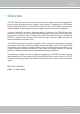
VIVOTEK Overview VIVOTEK FD8169 is an easy-to-use fixed dome network camera specifically designed for indoor security applications with a compact, stylish exterior. Equipped with a 2MP sensor enabling viewing resolution of 1920x1080 at a smooth 30 fps, the FD8169 is an all-in-one camera capable of capturing high quality and high resolution video up to 2 Megapixel.
VIVOTEK Read Before Use The use of surveillance devices may be prohibited by law in your country. The Network Camera is not only a high-performance web-ready camera but can also be part of a flexible surveillance system. It is the user’s responsibility to ensure that the operation of such devices is legal before installing this unit for its intended use. It is important to first verify that all contents received are complete according to the Package Contents listed below.
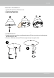
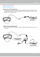
VIVOTEK Hardware Installation 1. Loosen the screw on the dome cover. 2. Press the release button. 3. Remove the dome cover. 1 3 2 4. Install the SD card. 5. Attach the alignment sticker to preferred location. Drill anchor holes and cabling holes into the ceiling or wall. 6. Route an Ethernet cable and DC wires (if preferred) through the hole.
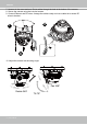
VIVOTEK 7. Hammer in the screw anchors. Route cables through the hole at the bottom of the camera. 8. Secure the camera using the included screws. 9. Connect Ethernet and DC wires. Arrange the cables neatly and use a cable tie to secure DC wires to bracket. 9 7 8 10. Adjust the camera lens shooting angle.
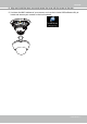
VIVOTEK 11. Align and install the dome cover and secure the cover with the screw on the side. 12. Jot down the MAC address of your camera, and use the included IW2 software utility to locate and access your camera on the local network.
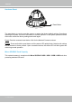
VIVOTEK Hardware Reset Reset Button The reset button is used to reset the system or restore the factory default settings. Sometimes resetting the system can return the camera to normal operation. If the system problems remain after reset, restore the factory settings and install again. Reset: Press the recessed reset button. Wait for the Network Camera to reboot. Restore: Press and hold the reset button until the status LED rapidly blinks. Note that all settings will be restored to factory default.
VIVOTEK Network Deployment General Connection (PoE) When using a PoE-enabled switch The Network Camera is PoE-compliant, allowing transmission of power and data via a single Ethernet cable. Follow the below illustration to connect the Network Camera to a PoEenabled switch via Ethernet cable. POWER COLLISION 1 2 3 4 LINK RECEIVE PARTITION 5 PoE Switch When using a non-PoE switch Use a PoE power injector (optional) to connect between the Network Camera and a nonPoE switch.
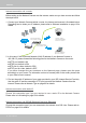
VIVOTEK Internet connection via a router Before setting up the Network Camera over the Internet, make sure you have a router and follow the steps below. 1. Connect your Network Camera behind a router, the Internet environment is illustrated below. Regarding how to obtain your IP address, please refer to Software Installation on page 12 for details. WAN (Wide Area Network ) Internet Router IP address : from ISP POWER COLLISION 1 2 3 4 5 IP address : 192.168.0.3 Subnet mask : 255.255.255.
VIVOTEK Configure the router, virtual server or firewall, so that the router can forward any data coming into a preconfigured port number to a network camera on the private network, and allow data from the camera to be transmitted to the outside of the network over the same path. From Forward to 122.146.57.120:8000 192.168.2.10:80 122.146.57.120:8001 192.168.2.11:80 ... ... When properly configured, you can access a camera behind the router using the HTTP request as follows: http://122.146.57.
VIVOTEK Software Installation Installation Wizard 2 (IW2), a software included in the product CD, helps you set up your Network Camera on the LAN. IW2 1. Install IW2 under the Software Utility directory from the software CD. Double-click the IW2 shortcut on your desktop to launch the program. Installation Wizard 2 2. The program will conduct an analysis of your network environment. After your network environment is analyzed, please click Next to continue the program. 3.
VIVOTEK Ready to Use 1. A browser session with the Network Camera should prompt as shown below. 2. You should be able to see live video from your camera. You may also install the 32-channel recording software from the software CD in a deployment consisting of multiple cameras. For its installation details, please refer to its related documents.
VIVOTEK Accessing the Network Camera This chapter explains how to access the Network Camera through web browsers, RTSP players, 3GPP-compatible mobile devices, and VIVOTEK recording software. Using Web Browsers Use Installation Wizard 2 (IW2) to access the Network Cameras on LAN. If your network environment is not a LAN, follow these steps to access the Netwotk Camera: 1. Launch your web browser (e.g., Microsoft® Internet Explorer or Mozilla Firefox). 2.
VIVOTEK ► By default, the Network Camera is not password-protected. To prevent unauthorized access, it is highly recommended to set a password for the Network Camera. For more information about how to enable password protection, please refer to Security on page 76. ► If you see a dialog box indicating that your security settings prohibit running ActiveX ® Controls, please enable the ActiveX ® Controls for your browser. 1. Choose Tools > Internet Options > Security > Custom Level. 2.
VIVOTEK IMPORTANT: • Currently the Network Camera utilizes 32-bit ActiveX plugin. You CAN NOT open a management/view session with the camera using a 64-bit IE browser. • If you encounter this problem, try execute the Iexplore.exe program from C:\Windows\ SysWOW64. A 32-bit version of IE browser will be installed. • On Windows 7, the 32-bit explorer browser can be accessed from here: C:\Program Files (x86)\Internet Explorer\iexplore.
VIVOTEK Using RTSP Players To view the streaming media using RTSP players, you can use one of the following players that support RTSP streaming. Quick Time Player VLC media player VLC media player 1. Launch the RTSP player. mpegable Player 2. Choose File > Open URL. A URL dialog box will pop up. 3.
VIVOTEK Using 3GPP-compatible Mobile Devices To view the streaming media through 3GPP-compatible mobile devices, make sure the Network Camera can be accessed over the Internet. For more information on how to set up the Network Camera over the Internet, please refer to Setup the Network Camera over the Internet on page 9. To utilize this feature, please check the following settings on your Network Camera: 1.
VIVOTEK Using VIVOTEK Recording Software The product software CD also contains an ST7501 recording software, allowing simultaneous monitoring and video recording for multiple Network Cameras. Please install the recording software; then launch the program to add the Network Camera to the Channel list. For detailed information about how to use the recording software, please refer to the user’s manual of the software or download it from http://www.vivotek.com.
VIVOTEK Main Page This chapter explains the layout of the main page. It is composed of the following sections: VIVOTEK INC. Logo, Host Name, Camera Control Area, Configuration Area, Menu, and Live Video Window. Resize Buttons VIVOTEK INC. Logo Host Name Configuration Area Camera Control Area Hide Button Live View Window VIVOTEK INC. Logo Click this logo to visit the VIVOTEK website. Host Name The host name can be customized to fit your needs.
VIVOTEK Configuration Area Client Settings: Click this button to access the client setting page. For more information, please refer to Client Settings on page 25. Configuration: Click this button to access the configuration page of the Network Camera. It is suggested that a password be applied to the Network Camera so that only the administrator can configure the Network Camera. For more information, please refer to Configuration on page 30.
VIVOTEK PTZ Panel: This Network Camera supports “digital“ (e-PTZ) pan/tilt/zoom control, which allows roaming a smaller view frame within a large view frame. Please refer to PTZ settiings on page 89 for detailed information. Global View: Click on this item to display the Global View window. The Global View window contains a full view image (the largest frame size of the captured video) and a floating frame (the viewing region of the current video stream).
VIVOTEK Video Control Buttons: Depending on the Network Camera model and Network Camera configuration, some buttons may not be available. Snapshot: Click this button to capture and save still images. The captured images will be displayed in a pop-up window. Right-click the image and choose Save Picture As to save it in JPEG (*.jpg) or BMP (*.bmp) format. Digital Zoom: Click and uncheck “Disable digital zoom” to enable the zoom operation.
VIVOTEK ■ The following window is displayed when the video mode is set to MJPEG: Video Title Title and Time Video (HTTP-V) 2014/07/25 17:08:56 Time Video 17:08:56 2014/07/25 Video Control Buttons Video Title: The video title can be configured. For more information, please refer to Media > Image on page 48. Time: Display the current time. For more information, please refer to Media > Image on page 48. Title and Time: Video title and time can be stamped on the streaming video.
VIVOTEK Client Settings This chapter explains how to select the stream transmission mode and saving options on the local computer. When completed with the settings on this page, click Save on the page bottom to enable the settings. H.264 Protocol Options H.264 Protocol Options Depending on your network environment, there are four transmission modes of H.264 streaming: UDP unicast: This protocol allows for more real-time audio and video streams.
VIVOTEK MP4 Saving Options Users can record live video as they are watching it by clicking page. Here, you can specify the storage destination and file name. Start MP4 Recording on the main Folder: Specify a storage destination on your PC for the recorded video files. The location can be changed. File name prefix: Enter the text that will be appended to the front of the video file name. A specified folder will be automatically created on your local hard disk.
VIVOTEK Joystick settings Enable Joystick Connect a joystick to a USB port on your management computer. Supported by the plug-in (Microsoft’s DirectX), once the plug-in for the web console is loaded, it will automatically detect if there is any joystick on the computer. The joystick should work properly without installing any other driver or software. Then you can begin to configure the joystick settings of connected devices. Please follow the instructions below to enable joystick settings. 1.
VIVOTEK Buttons Configuration In the Button Configuration window, the left column shows the actions you can assign, and the right column shows the functional buttons and assigned actions. The number of buttons may differ from different joysticks. Please follow the steps below to configure your joystick buttons: 1. Choosing one of the actions and click Assign will pop up a dialog. Then you can assign this action to a button by pressing the joystick button or select it from the drop-down list.
VIVOTEK Buttons Configuration Click the Configure Buttons button, a window will prompt as shown below. Please follow the steps below to configure your joystick buttons: 1. Select a button number from the Button # pull-down menu. Tips: If you are not sure of the locations of each button, use the Properties window in the Game Controllers utility. 2. Select a corresponding action, such as Patrol or Preset#. 3. Click the Assign button to assign an action to the button.
VIVOTEK Configuration Click Configuration on the main page to enter the camera setting pages. Note that only Administrators can access the configuration page. VIVOTEK provides an easy-to-use user interface that helps you set up your network camera with minimal effort. In order to simplify the user interface, detailed information will be hidden unless you click on the function item.
VIVOTEK System > General settings This section explains how to configure the basic settings for the Network Camera, such as the host name and system time. It is composed of the following two columns: System, and System Time. When finished with the settings on this page, click Save at the bottom of the page to enable the settings. System Host name: Enter a desired name for the Network Camera.
VIVOTEK System time Keep current date and time: Select this option to preserve the current date and time of the Network Camera. The Network Camera’s internal real-time clock maintains the date and time even when the power of the system is turned off. Synchronize with computer time: Select this option to synchronize the date and time of the Network Camera with the local computer. The read-only date and time of the PC is displayed as updated. Manual: The administrator can enter the date and time manually.
VIVOTEK System > Homepage layout This section explains how to set up your own customized homepage layout. General settings This column shows the settings of your hompage layout. You can manually select the background and font colors in Theme Options (the second tab on this page). The settings will be displayed automatically in this Preview field. The following shows the homepage using the default settings: ■ Hide Powered by VIVOTEK: If you check this item, it will be removed from the homepage.
VIVOTEK Theme Options Here you can change the color of your homepage layout. There are three types of preset patterns for you to choose from. The new layout will simultaneously appear in the Preview filed. Click Save to enable the settings.
VIVOTEK ■ Follow the steps below to set up the customed homepage: 1. Click Custom on the left column. 2. Click the field where you want to change the color on the right column. Color Selector Custom Pattern 3. The palette window will pop up as shown below. 2 3 1 4 4. Drag the slider bar and click on the left square to select a desired color. 5. The selected color will be displayed in the corresponding fields and in the Preview column. 6. Click Save to enable the settings.
VIVOTEK System > Logs This section explains how to configure the Network Camera to send the system log to a remote server as backup. Log server settings Follow the steps below to set up the remote log: 1. Select Enable remote log. 2. In the IP address text box, enter the IP address of the remote server. 2. In the port text box, enter the port number of the remote server. 3. When completed, click Save to enable the setting.
VIVOTEK You can install the included ST7501 recording software, which provides an Event Management function group for delivering event messages via emails, GSM short messages, onscreen event panel, or to trigger an alarm, etc. For more information, refer to the ST7501 User Manual.
VIVOTEK Access log Access log displays the access time and IP address of all viewers (including operators and administrators) in a chronological order. The access log is stored in the Network Camera’s buffer area and will be overwritten when reaching a certain limit. System > Parameters The View Parameters page lists the entire system’s parameters. If you need technical assistance, please provide the information listed on this page.
VIVOTEK System > Maintenance This chapter explains how to restore the Network Camera to factory default, upgrade firmware version, etc. General settings > Upgrade firmware This feature allows you to upgrade the firmware of your Network Camera. It takes a few minutes to complete the process. Note: Do not power off the Network Camera during the upgrade! Follow the steps below to upgrade the firmware: 1. Download the latest firmware file from the VIVOTEK website. The file is in .pkg file format. 2.
VIVOTEK General settings > Restore This feature allows you to restore the Network Camera to factory default settings. Network: Select this option to retain the Network Type settings (please refer to Network Type on page 60). Daylight Saving Time: Select this option to retain the Daylight Saving Time settings (please refer to Import/Export files below on this page). Custom Language: Select this option to retain the Custom Language settings.
VIVOTEK 3. Open the file with Microsoft® Notepad and locate your time zone; set the start and end time of DST. When completed, save the file. In the example below, DST begins each year at 2:00 a.m. on the second Sunday in March and ends at 2:00 a.m. on the first Sunday in November. Update daylight saving time rules: Click Browse… and specify the XML file to update. If the incorrect date and time are assigned, you will see the following warning message when uploading the file to the Network Camera.
VIVOTEK The following message is displayed when attempting to upload an incorrect file format. Export language file: Click to export language strings. VIVOTEK provides nine languages: English, Deutsch, Español, Français, Italiano, 日本語, Português, 簡体中文, and 繁體中文. Update custom language file: Click Browse… and specify your own custom language file to upload. Export configuration file: Click to export all parameters for the device and user-defined scripts.
VIVOTEK Media > Image This section explains how to configure the image settings of the Network Camera. It is composed of the following four columns: General settings, Picture settings, Exposure, and Privacy mask. General settings Video title Show_timestamp_and video_title_in_video_and_snapshots: Enter a name that will be displayed on the title bar of the live video as the picture shown below.
VIVOTEK Day/Night Settings Switch to B/W in night mode Select this to enable the Network Camera to automatically switch to Black/White during night mode. Turn on built-in IR illuminator in night mode Select this to turn on the camera’s onboard IR illuminator when the camera detects low light condition and enters the night mode.
VIVOTEK Smart IR When enabled, the camera automatically adjust the IR projection to adjacent objects in order to avoid over-exposure in the night mode. The Smart IR function is more beneficial when the spot of intrusions or an object of your interest is close to the lens and the IR lights. For example, if an intruder has a chance of getting near the range of 3 meters, Smart IR can effectively reduce the over-exposure. For a surveillance area at a greater distance, e.g.
VIVOTEK Tips: If there is an object in close proximity, the IR lights reflected back from it can mislead the Smart IR’s calculation of light level. To solve this issue, you can place an “Exposure Exclude” window on an unavoidable object in the Exposure setting window. See page 51 for how to do it. You can also configure the “Exposure Exclude” window in a night mode “Profile” setting so that your day time setting is not affected.
VIVOTEK ■ Schedule mode The Network Camera switches between day mode and night mode based on a specified schedule. Enter the start and end time for day mode. Note that the time format is [hh:mm] and is expressed in 24-hour clock time. By default, the start and end time of day mode are set to 07:00 and 18:00. Sensitivity Tune the responsiveness of the IR filter to lighting conditions as Low, Normal, or High. When completed with the settings on this page, click Save to enable the settings.
VIVOTEK Image settings On this page, you can tune the White balance and Image adjustment. Sensor Setting 1: For normal situations Sensor Setting 2: For special situations White balance: Adjust the value for the best color temperature. ■ You may follow the steps below to adjust the white balance to the best color temperature. 1.
VIVOTEK Noise reduction ■ Enable noise reduction: Check to enable noise reduction in order to reduce noises and flickers in image. This applies to the onboard 3D Noise Reduction feature. Use the pull-down menu to adjust the reduction strength. Note that applying this function to the video channel will consume system computing power. 3D Noise Reduction is mostly applied in low-light conditions. When enabled in a low-light condition with fast moving objects, trails of after-images may occur.
VIVOTEK Exposure On this page, you can set the Exposure measurement window, Exposure level, Exposure mode, Exposure time, Gain control, and Day/Night mode settings. You can configure two sets of Exposure settings: one for normal situations, the other for special situations, such as the day/night/schedule mode. Sensor Setting 1: For normal situations Sensor Setting 2: For special situations Measurement Window: This function allows users to set measurement window(s) for low light compensation.
VIVOTEK The inclusive window refers to the “weighed window“; the exclusive window refers to “ignored window“. It adopts the weighed averages method to calculate the value. The inclusive windows have a higher priority. You can overlap these windows, and, if you place an exclusive window within a larger inclusive window, the exclusive part of the overlapped windows will be deducted from the inclusive window. An exposure value will then be calculated out of the remaining of the inclusive window.
VIVOTEK You can click Restore to recall the original settings without incorporating the changes. When completed with the settings on this page, click Save to enable the settings. If you want to configure another sensor setting for day/night/schedule mode, please click Profile to open the Profile of exposure settings page as shown below. Activated period: Select the mode this profile to apply to: Day mode, Night mode, or Schedule mode. Please manually enter a range of time if you choose Schedule mode.
VIVOTEK Privacy mask Click Privacy Mask to open the settings page. On this page, you can block out sensitive zones to address privacy concerns. 2013/12/09 17:08:56 ■ To set the privacy mask windows, follow the steps below: 1. Click New to add a new window. 2. You can use the mouse cursor to size and drag-drop the window, which is recommended to be at least twice the size of the object (height and width) you want to cover. 3. Enter a Window Name and click Save to enable the setting. 4.
VIVOTEK Media > Video Stream settings This Network Camera supports multiple streams with frame sizes ranging from 176 x 144 to 1920 x 1080 pixels. The definition of multiple streams: ■ Stream 1: Users can define the "Region of Interest" (viewing region) and the "Output Frame Size" (size of the live view window). ■ Stream 2: The default frame size for Stream 2 is set to the 1920 x 1080.
VIVOTEK Please follow the steps below to set up those settings for a stream: 1. Select a stream for which you want to set up the viewing region. 2. Select a Region of Interest from the drop-down list. The floating frame, the same as the one in the Gloabl View window on the home page, will resize accordingly. If you want to set up a customized viewing region, you can also resize and drag the floating frame to a desired position with your mouse. 3.
VIVOTEK Click the stream item to display the detailed information. The maximum frame size will follow your settings in the above Viewing Window sections. This Network Camera offers real-time H.264 and MJPEG compression standards (Dual Codec) for real-time viewing. If the H.264 mode is selected, the video is streamed via RTSP protocol. There are several parameters through which you can adjust the video performance: ■ Frame size You can set up different video resolution for different viewing devices.
VIVOTEK The frame rate will decrease if you select a higher resolution. ■ Intra frame period Determine how often for firmware to plant an I frame. The shorter the duration, the more likely you will get better video quality, but at the cost of higher network bandwidth consumption. Select the intra frame period from the following durations: 1/4 second, 1/2 second, 1 second, 2 seconds, 3 seconds, and 4 seconds.
VIVOTEK If JPEG mode is selected, the Network Camera sends consecutive JPEG images to the client, producing a moving effect similar to a filmstrip. Every single JPEG image transmitted guarantees the same image quality, which in turn comes at the expense of variable bandwidth usage. Because the media contents are a combination of JPEG images, no audio data is transmitted to the client.
VIVOTEK Network > General settings This section explains how to configure a wired network connection for the Network Camera. Network Type LAN Select this option when the Network Camera is deployed on a local area network (LAN) and is intended to be accessed by local computers. The default setting for the Network Type is LAN. Please rememer to click on the Save button when you complete the Network setting.
VIVOTEK Primary DNS: The primary domain name server that translates hostnames into IP addresses. Secondary DNS: Secondary domain name server that backups the Primary DNS. Primary WINS server: The primary WINS server that maintains the database of computer names and IP addresses. Secondary WINS server: The secondary WINS server that maintains the database of computer names and IP addresses.
VIVOTEK NOTE: ► If the default ports are already used by other devices connected to the same router, the Network Camera will select other ports for the Network Camera. ► If UPnP TM is not supported by your router, you will see the following message: Error: Router does not support UPnP port forwarding. ► Steps to enable the UPnP TM user interface on your computer: Note that you must log on to the computer as a system administrator to install the UPnP TM components. 1.
VIVOTEK 4. In the Networking Services dialog box, select Universal Plug and Play and click OK. 5. Click Next in the following window. 6. Click Finish. UPnP TM is enabled. ► How does UPnP TM work? UPnP TM networking technology provides automatic IP configuration and dynamic discovery of devices added to a network. Services and capabilities offered by networked devices, such as printing and file sharing, are available among each other without the need for cumbersome network configuration.
VIVOTEK Enable IPv6 Select this option and click Save to enable IPv6 settings. Please note that this only works if your network environment and hardware equipment support IPv6. The browser should be Microsoft® Internet Explorer 6.5, Mozilla Firefox 3.0 or above. When IPv6 is enabled, by default, the network camera will listen to router advertisements and be assigned with a link-local IPv6 address accordingly. IPv6 Information: Click this button to obtain the IPv6 information as shown below.
VIVOTEK Please follow the steps below to link to an IPv6 address: 1. Open your web browser. 2. Enter the link-global or link-local IPv6 address in the address bar of your web browser. 3. The format should be: http://[2001:0c08:2500:0002:0202:d1ff:fe04:65f4]/ IPv6 address 4. Press Enter on the keyboard or click Refresh button to refresh the webpage.
VIVOTEK Port HTTPS port: By default, the HTTPS port is set to 443. It can also be assigned to another port number between 1025 and 65535. FTP port: The FTP server allows the user to save recorded video clips. You can utilize VIVOTEK's Installation Wizard 2 to upgrade the firmware via FTP server. By default, the FTP port is set to 21. It also can be assigned to another port number between 1025 and 65535.
VIVOTEK Network > Streaming protocols HTTP streaming To utilize HTTP authentication, make sure that your have set a password for the Network Camera first; please refer to Security > User account on page 76 for details. Authentication: Depending on your network security requirements, the Network Camera provides two types of security settings for an HTTP transaction: basic and digest.
VIVOTEK URL command -- http://:/ For example, when the Access name for stream 2 is set to video2.mjpg: 1. Launch Mozilla Firefox or Netscape. 2. Type the above URL command in the address bar. Press Enter. 3. The JPEG images will be displayed in your web browser. http://192.168.5.151/video2.
VIVOTEK Authentication: Depending on your network security requirements, the Network Camera provides three types of security settings for streaming via RTSP protocol: disable, basic, and digest. If basic authentication is selected, the password is sent in plain text format, but there can be potential risks of it being intercepted. If digest authentication is selected, user credentials are encrypted using MD5 algorithm, thus providing better protection against unauthorized access.
VIVOTEK Multicast settings for streams: Click the items to display the detailed configuration information. Select the Always multicast option to enable multicast for video streams. Unicast video transmission delivers a stream through point-to-point transmission; multicast, on the other hand, sends a stream to the multicast group address and allows multiple clients to acquire the stream at the same time by requesting a copy from the multicast group address.
VIVOTEK Network > DDNS This section explains how to configure the dynamic domain name service for the Network Camera. DDNS is a service that allows your Network Camera, especially when assigned with a dynamic IP address, to have a fixed host and domain name. Express link Express Link is a free service provided by VIVOTEK server, which allows users to register a domain name for a network device. One URL can only be mapped to one MAC address.
VIVOTEK Manual setup DDNS: Dynamic domain name service Enable DDNS: Select this option to enable the DDNS setting. Provider: Select a DDNS provider from the provider drop-down list. VIVOTEK offers Safe100.net, a free dynamic domain name service, to VIVOTEK customers. It is recommended that you register Safe100.net to access VIVOTEK’s Network Cameras from the Internet. Additionally, we offer other DDNS providers, such as Dyndns.org(Dynamic), Dyndns. org(Custom), TZO.com, DHS.
VIVOTEK [Register] Successfully Your account information has been mailed to registered e-mail address 4. Select Enable DDNS and click Save to enable the setting. ■ CustomSafe100 VIVOTEK offers documents to establish a CustomSafe100 DDNS server for distributors and system integrators. You can use CustomSafe100 to register a dynamic domain name if your distributor or system integrators offer such services. 1. In the DDNS column, select CustomSafe100 from the drop-down list. 2.
VIVOTEK Network > QoS (Quality of Service) Quality of Service refers to a resource reservation control mechanism, which guarantees a certain quality to different services on the network. Quality of service guarantees are important if the network capacity is insufficient, especially for real-time streaming multimedia applications. Quality can be defined as, for instance, a maintained level of bit rate, low latency, no packet dropping, etc.
VIVOTEK QoS/DSCP (the DiffServ model) DSCP-ECN defines QoS at Layer 3 (Network Layer). The Differentiated Services (DiffServ) model is based on packet marking and router queuing disciplines. The marking is done by adding a field to the IP header, called the DSCP (Differentiated Services Codepoint). This is a 6-bit field that provides 64 different class IDs. It gives an indication of how a given packet is to be forwarded, known as the Per Hop Behavior (PHB).
VIVOTEK Network > SNMP (Simple Network Management Protocol) This section explains how to use the SNMP on the network camera. The Simple Network Management Protocol is an application layer protocol that facilitates the exchange of management information between network devices. It helps network administrators to remotely manage network devices and find, solve network problems with ease.
VIVOTEK Security > User accounts This section explains how to enable password protection and create multiple accounts. Root Password The administrator account name is “root”, which is permanent and can not be deleted. If you want to add more accounts in the Manage User column, please apply the password for the “root” account first. 1. Type the password identically in both text boxes, then click Save to enable password protection. 2.
VIVOTEK Security > HTTPS (Hypertext Transfer Protocol over SSL) This section explains how to enable authentication and encrypted communication over SSL (Secure Socket Layer). It helps protect streaming data transmission over the Internet on higher security level. Create and Install Certificate Method Before using HTTPS for communication with the Network Camera, a Certificate must be created first.
VIVOTEK 5. Click Save to preserve your configuration, and your current session with the camera will change to the encrypted connection. 6. If your web session does not automatically change to an encrypted HTTPS session, click Home to return to the main page. Change the URL address from “http://” to “https://“ in the address bar and press Enter on your keyboard. Some Security Alert dialogs will pop up. Click OK or Yes to enable HTTPS. https:// https://192.168.5.151/index.
VIVOTEK Create certificate request and install 1. Select the option from the Method pull-down menu. 2. Click Create certificate to proceed. 3. The following information will show up in a pop-up window after clicking Create. Then click Save to generate the certificate request. 4. The Certificate request window will prompt. If you see the following Information bar, click OK and click on the Information bar at the top of the page to allow pop-ups.
VIVOTEK 5. Look for a trusted certificate authority, such as Symantec’s VeriSign Authentication Services, that issues digital certificates. Sign in and purchase the SSL certification service. Copy the certificate request from your request prompt and paste it in the CA’s signing request window. Proceed with the rest of the process as CA’s instructions on their webpage. 6. Once completed, your SSL certificate should be delivered to you via an email or other means.
VIVOTEK 7. Open a new edit, paste the certificate contents, and press ENTER at the end of the contents to add an empty line. 8. Convert file format from DOS to UNIX. Open File menu > Conversions > DOS to Unix.
VIVOTEK 9. Save the edit using the “.crt” extension, using a file name like “CAcert.crt.” 10. Return to the original firmware session, use the Browse button to locate the crt certificate file, and click Upload to enable the certification.
VIVOTEK 11. When the certifice file is successfully loaded, its status will be stated as Active. Note that a certificate must have been created and installed before you can click on the “Save" button for the configuration to take effect. 12.To begin an encrypted HTTPS session, click Home to return to the main page. Change the URL address from “http://” to “https://“ in the address bar and press Enter on your keyboard. Some Security Alert dialogs will pop up. Click OK or Yes to enable HTTPS.
VIVOTEK Security > Access List This section explains how to control access permission by verifying the client PC’s IP address. General Settings Maximum number of concurrent streaming connection(s) limited to: Simultaneous live viewing for 1~10 clients (including stream 1 to stream 3). The default value is 10. If you modify the value and click Save, all current connections will be disconnected and automatically attempt to re-link (IE Explorer or Quick Time Player).
VIVOTEK ■ Refresh: Click this button to refresh all current connections. ■ Add to deny list: You can select entries from the Connection Status list and add them to the Deny List to deny access. Please note that those checked connections will only be disconnected temporarily and will automatically try to re-link again (IE Explore or Quick Time Player). If you want to enable the denied list, please check Enable access list filtering and click Save in the first column.
VIVOTEK There are three types of rules: Single: This rule allows the user to add an IP address to the Allowed/Denied list. For example: 192.168.2.1 Network: This rule allows the user to assign a network address and corresponding subnet mask to the Allow/Deny List. The address and network mask are written in CIDR format. For example: IP address range 192.168.2.x will be bolcked. If IPv6 filter is preferred, you will be prompted by the following window.
VIVOTEK Security > IEEE 802.1X Enable this function if your network environment uses IEEE 802.1x, which is a port-based network access control. The network devices, intermediary switch/access point/hub, and RADIUS server must support and enable 802.1x settings. The 802.1x standard is designed to enhance the security of local area networks, which provides authentication to network devices (clients) attached to a network port (wired or wireless).
VIVOTEK 3. When all settings are complete, move the Network Camera to the protected LAN by connecting it to an 802.1x enabled switch. The devices will then start the authentication automatically. NOTE: ► The authentication process for 802.1x: 1. The Certificate Authority (CA) provides the required signed certificates to the Network Camera (the supplicant) and the RADIUS Server (the authentication server). 2. A Network Camera requests access to the protected LAN using 802.
VIVOTEK PTZ > PTZ settings This section explains how to control the Network Camera’s Pan/Tilt/Zoom operation. There are two ways to enable the camera control function: Digital: Control the e-PTZ operation. Within a field of view,it allows users to quickly move the focus to a target area for close-up viewing without physically moving the camera. Digital PTZ Operation (E-PTZ Operation) The e-PTZ control settings section will be displayed as shown below: 2014/08/20 09:57:30 x1.8 x1.
VIVOTEK Home page in the E-PTZ Mode x3.3 ■ The e-Preset Positions will also be displayed on the home page. Select one from the drop-down list, and the Network Camera will move to the selected position. ■ If you have set up different preset positions for different streams, you can select one of the video streams to display its separate preset positions.
VIVOTEK Patrol settings You can select some preset positions for the Network Camera to patrol. Please follow the steps below to set up a patrol schedule: 1. Select the preset locations on the list, and click . 2. The selected preset locations will be displayed on the Patrol locations list. 3. Set the Dwelling time for the preset location during an auto patrol. 4. If you want to delete a preset location from the Patrol locations list, select it and click Remove. 5.
VIVOTEK NOTE: ► The Preset Positions will also be displayed on the Home page. Select one from the Go to menu, and the Network Camera will move to the selected preset position. ► Click Patrol: The Network Camera will patrol along the selected positions repeatedly.
VIVOTEK Event > Event settings This section explains how to configure the Network Camera to respond to particular situations (event). A typical application is that when a motion is detected, the Network Camera sends buffered images to an FTP server or e-mail address as notifications. Click on Help, there is an illustration shown in the pop-up window explaining that an event can be triggered by many sources, such as motion detection or external digital input devices.
VIVOTEK ■ Event name: Enter a name for the event setting. ■ Enable this event: Select this option to enable the event setting. ■ Priority: Select the relative importance of this event (High, Normal, or Low). Events with a higher priority setting will be executed first. ■ Detect next event after seconds: Enter the duration in seconds to pause motion detection after a motion is detected. This can prevent event-related actions to take place too frequently. 1.
VIVOTEK ■ Camera tampering detection This option allows the Network Camera to trigger when the camera detects that is is being tampered with. To enable this function, you need to configure the Tampering Detection option first. Please refer to page 109 for detailed information. ■ Manual Trigger This option allows users to enable event triggers manually by clicking the on/off button on the homepage. Please configure 1 to 3 associated events before using this function. 3.
VIVOTEK Add server It is necessary to configure the server and media settings so that the Network Camera will know what action to take (such as which server to send the media files to) when a trigger is activated. Click Add server to open the server setting window. You can specify where the notification messages are sent to when a trigger is activated. A total of 5 server settings can be configured. There are four choices of server types available: Email, FTP, HTTP, and Network storage.
VIVOTEK To verify if the email settings are correctly configured, click Test. The result will be shown in a pop-up window. If successful, you will also receive an email indicating the result. Click Save server to enable the settings. Note that after you configure the first event server, the new event server will automatically display on the Server list. If you wish to add other server options, click Add server. Server type - FTP Select to send the media files to an FTP server when a trigger is activated.
VIVOTEK ■ Passive mode Most firewalls do not accept new connections initiated from external requests. If the FTP server supports passive mode, select this option to enable passive mode FTP and allow data transmission to pass through the firewall. The firmware default has the Passive mode checkbox selected. To verify if the FTP settings are correctly configured, click Test. The result will be shown in a pop-up window as shown below. If successful, you will also receive a test.txt file on the FTP server.
VIVOTEK Network storage: Select to send the media files to a networked storage when a trigger is activated. Please refer to NAS server on page 113 for details. Note that only one NAS server can be configured. Click Save server to enable the settings. ■ SD Test: Click to test your SD card. The system will display a message indicating the result as a success or a failure. If you want to use your SD card for local storage, please format it before use. Please refer to page 101 for detailed information.
VIVOTEK Click 20140120 to open the directory: The format is: HH (24r) Click to open the file list for that hour 2014/01/20 2014/01/20 Click to go back to the previous level of the directory Click to delete selected items Click to delete all recorded data 2014/01/20 2014/01/20 The format is: File name prefix + Minute (mm) You can set up the file name prefix on Add media page. Please refer to next page for detailed information.
VIVOTEK Add media Click Add media to open the media setting window. You can specify the type of media that will be sent when a trigger is activated. A total of 5 media settings can be configured. There are three choices of media types available: Snapshot, Video Clip, and System log. Select the item to display the detailed configuration options. You can configure either one or all of them. Media type - Snapshot Select to send snapshots when a trigger is activated.
VIVOTEK ■ Add date and time suffix to the file name Select this option to add a date/time suffix to the file name. For example: Snapshot_20101213_100341 File name prefix Date and time suffix The format is: YYYYMMDD_HHMMSS Click Save media to enable the settings. Note that after you set up the first media server, a new column for media server will automatically display on the Media list. If you wish to add more media options, click Add media.
VIVOTEK ■ Maximum file size Specify the maximum file size allowed. Some users may need to stitch the video clips together when searching and packing up forensic evidence. ■ File name prefix Enter the text that will be appended to the front of the file name. For example: Video_20101213_100341 File name prefix Date and time suffix The format is: YYYYMMDD_HHMMSS Click Save media to enable the settings. Media type - System log Select to send a system log when a trigger is activated.
VIVOTEK In the Event settings column, the Servers and Medias you configured will be listed; please make sure the Event -> Status is indicated as ON, in order to enable the event triggering action. When completed, click the Save event button to enable the settings and click Close to exit Event Settings page. The new Event / Server settings / Media will appear in the event drop-down list on the Event setting page.
VIVOTEK Customized Script This function allows you to upload a sample script (.xml file) to the webpage, which will save your time on configuring the settings. Please note that there is a limited number of customized scripts you can upload; if the current amount of customized scripts has reached the limit, an alert message will prompt. If you need more information, please contact VIVOTEK technical support.
VIVOTEK Applications > Motion detection This section explains how to configure the Network Camera to enable motion detection. A total of three motion detection windows can be configured. 2010/12/10 17:08:56 2014/07/20 Motion Detection Setting 1: For normal situations hallway Follow the steps below to enable motion detection: Follow the steps below to enable motion detection: Motion Detection Setting 2: For special situations 1. Click New to add a new motion detection window. 2.
VIVOTEK A green bar indicates that even though motions have been detected, the event has not been triggered because the image variations still fall under the preset threshold. Percentage = 30% If you want to configure other motion detection settings for day/night/schedule mode (e.g., for a different lighting condition), please click Profile to open the Motion Detection Profile Settings page as shown below. Another three motion detection windows can be configured on this page.
VIVOTEK NOTE NOTE: ► How does motion detection work? A C B D There are two motion detection parameters: Sensitivity and Percentage. In the illustration above, frame A and frame B are two sequential images. Pixel differences between the two frames are detected and highlighted in gray (frame C) and will be compared with the sensitivity setting. Sensitivity is a value that expresses the sensitivity to moving objects.
VIVOTEK Applications > Tampering detection This section explains how to set up camera tamper detection. With tamper detection, the camera is capable of detecting incidents such as redirection, blocking or defocusing, or even spray paint. Please follow the steps below to set up the camera tamper detection function: 1. Check Enable camera tampering detection. 2. Enter the tamper trigger duration. (10 sec. ~ 10 min.
VIVOTEK Recording > Recording settings This section explains how to configure the recording settings for the Network Camera. Recording Settings Insert your SD card and click here to test NOTE: ► Please remember to format your SD card via the camera’s web console (in the Local storage . SD card management page) when using it for the first time. Please refer to page 115 for detailed information. Recording Settings Click Add to open the recording setting window.
VIVOTEK If you enable adaptive recording on a camera, only when an event is triggered on Camera A will the server record the full frame rate streaming data; otherwise, it will only request the I frame data during normal monitoring, thus effectively saves bandwidths and storage space. NOTE: ► To enable adaptive recording, please make sure you’ve set up the trigger source such as Motion Detection, DI Device, or Manual Trigger.
VIVOTEK 2. Destination You can select the SD card or network storage (NAS) for the recorded video files. If you have not configured a NAS server, see details in the following. NAS server Click Add NAS server to open the server setting window and follow the steps below to set up: 1. Fill in the information for your server. For example: 3 Network storage path (\\server name or IP address\folder name) 1 2 4 User name and password for your server 2. Click Test to check the setting.
VIVOTEK If successful, you will receive a test.txt file on the networked storage device. 3. Enter a server name. 4. Click Save to complete the settings and click Close to exit the page. ■ Capacity: You can choose either the entire free space available or limit the reserved space. The recording size limit must be larger than the reserved amount for cyclic recording.
VIVOTEK If you want to enable recording notification, please click Event to configure event triggering settings. Please refer to Event > Event settings on page 93 for more details. When completed, select Enable this recording. Click Save to enable the setting and click Close to exit this page. When the system begins recording, it will send the recorded files to the network storage. The new recording name will appear in the drop-down list on the recording page as shown below.
VIVOTEK Local storage > SD card management This section explains how to manage the local storage on the Network Camera. Here you can view SD card status, and implement SD card control. SD card staus This column shows the status and reserved space of your SD card. Please remember to format the SD card when using for the first time. no SD card SD card control ■ Enable cyclic storage: Check this item if you want to enable cyclic recording.
VIVOTEK Local storage > Content management This section explains how to manage the content of recorded videos on the Network Camera. Here you can search and view the records and view the searched results. Searching and Viewing the Records This column allows the user to set up search criteria for recorded data. If you do not select any criteria and click Search button, all recorded data will be listed in the Search Results column. ■ File attributes: Select one or more items as your search criteria.
VIVOTEK Search Results The following is an example of search results. There are four columns: Trigger time, Media type, Trigger type, and Locked. Click to sort the search results in either direction. Numbers of entries displayed on one page Enter a key word to filter the search results Highlight an item ■ View: Click on a search result which will highlight the selected item in purple as shown above. Click the View button and a media window will pop up to play back the selected file.
VIVOTEK ■ Lock/Unlock: Select the desired search results, then click this button. The selected items will become Locked, which will not be deleted during cyclic recording. You can click again to unlock the selections. For example: Click to switch pages ■ Remove: Select the desired search results, then click this button to delete the files.
VIVOTEK Appendix URL Commands for the Network Camera 1. Overview For some customers who already have their own web site or web control application, the Network Camera/Video Server can be easily integrated through URL syntax. This section specifies the external HTTP-based application programming interface. The HTTP-based camera interface provides the functionality to request a single image, control camera functions (PTZ, output relay etc.), and get and set internal parameter values.
VIVOTEK 3. General CGI URL Syntax and Parameters When the CGI request includes internal camera parameters, these parameters must be written exactly as they are named in the camera or video server. The CGIs are organized in functionally-related directories under the cgi-bin directory. The file extension .cgi is required. Syntax: http:///cgi-bin/[/...]/. [?=[&=...
VIVOTEK 4. Security Level SECURITY LEVEL SUB-DIRECTORY DESCRIPTION 0 anonymous Unprotected. 1 [view] anonymous, viewer, dido, camctrl 1. Can view, listen, talk to camera. 2. Can control DI/DO, PTZ of the camera. 4 [operator] anonymous, viewer, dido, camctrl, operator Operator access rights can modify most of the camera’s parameters except some privileges and network options.
VIVOTEK 5. Get Server Parameter Values Note: The access right depends on the URL directory. Method: GET/POST Syntax: http:///cgi-bin/anonymous/getparam.cgi?[] [&…] http:///cgi-bin/viewer/getparam.cgi?[] [&…] http:///cgi-bin/operator/getparam.cgi?[] [&…] http:///cgi-bin/admin/getparam.cgi?[] [&…] Where the should be [_].
VIVOTEK Response: HTTP/1.0 200 OK\r\n Content-Type: text/html\r\n Context-Length: 33\r\n \r\n network_ipaddress=192.168.0.
VIVOTEK 6. Set Server Parameter Values Note: The access right depends on the URL directory. Method: GET/POST Syntax: http:///cgi-bin/anonymous/setparam.cgi? = [&=…][&return=] http:///cgi-bin/viewer/setparam.cgi? = [&=…][&return=] http:///cgi-bin/operator/setparam.
VIVOTEK Example: Set the IP address of server to 192.168.0.123: Request: http://myserver/cgi-bin/admin/setparam.cgi?network_ipaddress=192.168.0.123 Response: HTTP/1.0 200 OK\r\n Content-Type: text/html\r\n Context-Length: 33\r\n \r\n network_ipaddress=192.168.0.
VIVOTEK 7. Available parameters on the server This chapter defines all the parameters which can be configured or retrieved from VIVOTEK network camera or video server. The general format of description is listed in the table below Valid values: VALID VALUES DESCRIPTION string[] Text strings shorter than ‘n’ characters. The characters “,’, <,>,& are invalid. string[n~m] Text strings longer than `n’ characters and shorter than `m’ characters. The characters “,’, <,>,& are invalid.
VIVOTEK 7.1 system Group: system NAME VALUE DEFAULT SECURITY DESCRIPTION (get/set) hostname string[64] FD8169 1/6 Host name of server. ledoff 0 6/6 Turn on (0) or turn off (1) all led indicators. date time , date> 6/6 Current date of system. Set to ‘keep’ to keep date keep, unchanged. Set to ‘auto’ to auto use NTP to synchronize date. , 6/6 Current time of the system. Set to ‘keep’ to keep time unchanged.
VIVOTEK -200: GMT-05:00 Eastern Time, New York, Toronto -201: GMT-05:00 Bogota, Lima, Quito, Indiana -180: GMT-04:30 Caracas -160: GMT-04:00 Atlantic Time, Canada, La Paz, Santiago -140: GMT-03:30 Newfoundland -120: GMT-03:00 Brasilia, Buenos Aires, Georgetown, Greenland -80: GMT-02:00 Mid-Atlantic -40: GMT-01:00 Azores, Cape_Verde_IS.
VIVOTEK 200: GMT 05:00 Ekaterinburg, Islamabad, Karachi, Tashkent 220: GMT 05:30 Calcutta, Chennai, Mumbai, New Delhi 230: GMT 05:45 Kathmandu 240: GMT 06:00 Almaty, Novosibirsk, Astana, Dhaka, Sri Jayawardenepura 260: GMT 06:30 Rangoon 280: GMT 07:00 Bangkok, Hanoi, Jakarta, Krasnoyarsk 320: GMT 08:00 Beijing, Chongging, Hong Kong, Kuala Lumpur, Singapore, Taipei 360: GMT 09:00 Osaka, Sapporo, Tokyo, Seoul, Yakutsk 380: GMT 09:30 Adelaide, Darwin 400: GMT 10:00 Brisbane, Canberra, Melbourne, Sydney, Guam,
VIVOTEK updateinterval restore reset restoreexceptnet 0, 0 6/6 0 to Disable automatic time 3600, adjustment, otherwise, it 86400, indicates the seconds between 604800, NTP automatic update 2592000 intervals. 0, N/A 7/6 Restore the system after seconds. 0, N/A 7/6 Restart the server after seconds if is integer> non-negative.
VIVOTEK restoreexceptlang N/A 0, 7/6 Restore the system except the custom language file the user has uploaded. This command can cooperate with other “restoreexceptXYZ” commands. When cooperating with others, the system parameters will be restored to the default value except for a union of the combined results. 7.1.1 system.info Subgroup of system: info (The fields in this group are unchangeable.
VIVOTEK 简体中文 繁體中文 customlanguage_maxcount 1 0/6 Maximum number of custom languages supported on the server. customlanguage_count 0 0/6 Number of custom languages which have been uploaded to the server. customlanguage_i<0~(max string N/A 0/6 Custom language name. count-1)> 7.2 status Group: status NAME VALUE DEFAULT SECURITY DESCRIPTION (get/set) daynight day, night 0 7/7 Current status of day, night.
VIVOTEK user_i<1~20>_ view, privilege operator, 6/6 User privilege admin 7.4 network Group: network NAME VALUE DEFAULT SECURITY DESCRIPTION (get/set) preprocess follows: Bit 0 => HTTP service; Bit 1=> HTTPS service; Bit 2=> FTP service; Bit 3 => Two way audio and RTSP Streaming service; To stop service before changing its port settings.
VIVOTEK address> router 6/6 Default gateway. 6/6 Primary DNS server. 6/6 Secondary DNS server. 6/6 Primary WINS server. 6/6 Secondary WINS server. address> dns1 dns2 wins1 wins2 7.4.1 802.1x Subgroup of network: ieee8021x NAME VALUE DEFAULT SECURITY DESCRIPTION (get/set) enable 0 6/6 Enable/disable IEEE 802.
VIVOTEK 7.4.2 QOS Subgroup of network: qos_cos NAME VALUE DEFAULT SECURITY DESCRIPTION (get/set) enable 0 6/6 Enable/disable CoS (IEEE 802.
VIVOTEK 7.4.4 FTP Subgroup of network: ftp NAME VALUE DEFAULT SECURITY DESCRIPTION (get/set) port 21, 1025~65535 21 6/6 Local ftp server port. 7.4.5 HTTP Subgroup of network: http NAME VALUE DEFAULT SECURITY DESCRIPTION (get/set) port 80, 1025 ~ 80 1/6 HTTP port. 65535 alternateport 1025~65535 8080 6/6 Alternate HTTP port. authmode basic, basic 1/6 HTTP authentication mode. video.mjpg 1/6 HTTP server push access name for digest s0_accessname string[32] stream 1.
VIVOTEK 7.4.7 RTSP Subgroup of network: rtsp NAME VALUE DEFAULT SECURITY DESCRIPTION (get/set) port 554, 1025 ~ 554 1/6 RTSP port. 0 1/6 Enable anoymous streaming 65535 anonymousviewing viewing. authmode disable, disable 1/6 RTSP authentication mode. basic, digest s0_accessname string[32] live.sdp 1/6 RTSP access name for stream1. s1_accessname string[32] live2.sdp 1/6 RTSP access name for stream2. s2_accessname string[32] live3.
VIVOTEK 7.4.9 PPPoE Subgroup of network: pppoe NAME VALUE DEFAULT SECURITY DESCRIPTION (get/set) user string[128] 6/6 PPPoE account user name. pass password[64] 6/6 PPPoE account password. 7.5 IP Filter 7.5.1 ipfilter for ONVIF Group: ipfilter NAME VALUE DEFAULT SECURITY DESCRIPTION (get/set) enable 0 6/6 Enable access list filtering. admin_enable 0 6/6 Enable administrator IP address.
VIVOTEK 7.6 video input Group: videoin NAME VALUE DEFAULT SECURITY DESCRIPTION (get/set) cmosfreq 50, 60 60 4/4 CMOS frequency. whitebalance auto, auto 4/4 “auto” indicates auto white manual, balance. rbgain “manual” indicates keep current value. “rbgain” indicates using rgain and gbain. exposurelevel 0~12 6 4/4 Exposure level color 0, 1 1 4/4 0 =>monochrome 1 => color flip 0 4/4 Flip the image. mirror 0 4/4 Mirror the image.
VIVOTEK mode 0~ 0 "capability_vi deoin_c_n mode"-1 4/99 Indicate the video mode on use. maxgain 0~100 100 4/4 Manual set maximum gain value. mingain 0~100 0 4/4 Manual set minimum gain value. color 0, 1 1 4/4 0 =>monochrome 1 => color flip 0 4/4 Flip the image. mirror 0 4/4 Mirror the image.
VIVOTEK maxexposure 5~32000 30 4/4 Maximum exposure time. s<0~(m-1)>_codectype mjpeg, h264 h264 1/4 Video codec type. svc is only supported with stream 0. s<0~(m-1)>_resolution Reference 1920x1080 1/4 Video resolution in pixels. capability_vide oin_resolution s<0~(m-1)>_h264_intraper iod 250, 500, 1000, 2000, 3000, 4000 1000 4/4 Intra frame period in milliseconds.
VIVOTEK 0 choosing cbr in “ratecontrolmode”. s<0~(m-1)>_h264_maxframe 1~30 30 1/4 Set maximum frame rate in fps (for h264). s<0~(m-1)>_h264_profile 0~2 1 1/4 Indicate H264 profiles 0: baseline 1: main profile 2: high profile s<0~(m-1)>_mjpeg_priorit ypolicy framerate, imagequality framerate 4/4 The policy to apply when the target bit rate is not sufficient to satisfy current encoded conditions. “framerate” indicates frame rate first. “imagequality” indicates image quality first.
VIVOTEK 7.6.1.1 Alternative video input profiles per channel In addition to the primary setting of video input, there can be alternative profile video input setting for each channel which might be for different scene of light (daytime or nighttime). Group: videoin_profile_i<0~(m-1)> NAME VALUE DEFAULT SECURITY DESCRIPTION (get/set) enable 0 4/4 Enable/disable this profile setting policy day, night 4/4 The mode which the profile is applied to.
VIVOTEK 7.
VIVOTEK sharpness -3 ~ 3, 100 100 4/4 Adjust sharpness of image according to mode settings. sharpnesspercent 0~100 50 4/4 Adjust sharpness of image by percentage. Softer 0 <-> 100 Sharper gammacurve 0~100 0 4/4 Gamma curve. dnr_mode 0~1 1 4/4 3D noise reduction. 0: off 1: on dnr_strength 1~100 50 4/4 3D noise reduction strength. lowlightmode 1 4/4 Enable/disable low light mode.
VIVOTEK according to mode settings. profile_i0_sharpness -3~3,100 100 4/4 Adjust sharpness of image according to mode settings. profile_i0_sharpnessperce nt 0~100 50 4/4 Adjust sharpness value of percentage when sharpness=100 profile_i0_gammacurve 0~100 0 4/4 Gamma curve profile_i0_dnr_mode 0~1 1 4/4 3D noise reduction. 0: off 1: on profile_i0_dnr_strength 1~100 50 4/4 3D noise reduction strength. profile_i0_lowlightmode 1 4/4 Enable/disable low light mode. 7.
VIVOTEK win_i<0~2>_width 0 ~ 320 0 4/4 Width of motion detection window. win_i<0~2>_height 0 ~ 240 0 4/4 Height of motion detection window. win_i<0~2>_objsize 0 ~ 100 0 4/4 Percent of motion detection window. win_i<0~2>_sensitivity 0 ~ 100 0 4/4 Sensitivity of motion detection window. Group: motion_c<0~(n-1)> profile for m profile and n channel product (capability.
VIVOTEK 7.11 Tampering detection settings Group: tampering_c<0~(n-1)> for n channel product NAME VALUE DEFAULT SECURITY DESCRIPTION (get/set) enable 0 4/4 Enable or disable tamper detection. duration 10 ~ 600 10 4/4 If tampering value exceeds the ‘threshold’ for more than ‘duration’ second(s), then tamper detection is triggered. 7.12 DDNS Group: ddns NAME VALUE DEFAULT SECURITY DESCRIPTION (get/set) enable 0 6/6 Enable or disable the dynamic DNS.
VIVOTEK 7.12.1 Express link Group:expresslink NAME VALUE DEFAULT SECURITY DESCRIPTION (get/set) enable 0 6/6 Enable or disable express link. state onlycheck, badnetwork 6/6 “onlycheck” : You have to input the onlyoffline, host name of your camera and press checkonline, "Register" button to register it. badnetwork “onlyoffline” : Express link is active, you can now connect to this camera at expresslink_url. “checkonline” : Express link is not active.
VIVOTEK 7.15 System log Group: syslog NAME VALUE DEFAULT SECURITY DESCRIPTION (get/set) enableremotelog 0 6/6 Enable remote log. serverip 6/6 Log server IP address. serverport 514, 1025~65535 514 6/6 Server port used for log.
VIVOTEK authpwrw string[8~128] 6/6 Read/write authentication password authpwro string[8~128] 6/6 Read only authentication password authtyperw MD5,SHA MD5 6/6 Read/write authentication type authtypero MD5,SHA MD5 6/6 Read only authentication type encryptpwrw string[8~128] 6/6 Read/write passwrd encryptpwro string[8~128] 6/6 Read only password encrypttyperw DES DES 6/6 Read/write encryption type encrypttypero DES DES 6/6 Read only encrypt
VIVOTEK theme_color_videobackground string[7] #565656 1/6 Background color of video area. theme_color_case string[7] #323232 1/6 Frame color custombutton_manualtrigger_s 1 1/6 Show or hide manual trigger how (VI) button in homepage 0 -> Hidden 1 -> Visible 7.18 Privacy mask Group: privacymask_c<0~(n-1)> for n channel product NAME VALUE DEFAULT SECURITY DESCRIPTION (get/set) enable 0 4/4 Enable privacy mask.
VIVOTEK npir 0, 0 0/99 Number of PIRs. 0 0/99 Number of digital inputs. 3 0/99 Number of virtual inputs ndi 0, nvi 0, (manual trigger) ndo 0, 0/99 0 naudioin 0, 0 0/99 Number of audio inputs. 0 0/99 Number of audio naudioout 0, outputs. nvideoin
VIVOTEK 0(not support), 1(support) Bit 1 => Built-in or external video source; 0(external), 1(built-in) Bit 2 => Support pan operation, 0(not support), 1(support) Bit 3 => Support tilt operation; 0(not support), 1(support) Bit 4 => Support zoom operation; 0(not support), 1(support) Bit 5 => Support focus operation; 0(not support), 1(support) Bit 6 => Support iris operation; 0(not support), 1(support) Bit 7 => External or built-in PT; 0(built-in), 1(external) Bit 8 => Invalidate bit 1 ~ 7; 0(bit 1 ~ 7 are v
VIVOTEK windowless 0/99 1 Indicate whether to support windowless plug-in. eptz 0, follows: Bit 0 => stream 1 supports ePTZ or not. Bit 1 => stream 2 supports ePTZ or not. The rest may be deduced by analogy remotefocus 0/99 0 Indicate whether to support remote focus function. npreset 0,
VIVOTEK protocol_rtp_http 0/99 1 Indicate whether to support RTP over HTTP. protocol_spush_mjpeg 0/99 1 Indicate whether to support server push MJPEG. protocol_snmp 0/99 1 Indicate whether to support SNMP. protocol_ipv6 0/99 1 Indicate whether to support IPv6. protocol_pppoe 0/99 1 Indicate whether to support PPPoE. protocol_ieee8021x 0/99 1 Indicate whether to support IEEE802.1x.
VIVOTEK available resolution list> options (listed in "resolution") in current video mode. videoin_maxframerate 30, 30, 30, 30, 30, 30, 30 0/99 Available maximum frame list. videoin_mjpeg_maxframera te 30, 30, 30, 30, 30, 30, 30 0/99 Available maximum codec frame list.
VIVOTEK audio_linein 0/99 0 Indicate whether to support external line input. (It will be replaced by audio_mic and audio_extmic.) audio_lineout 0/99 0 Indicate whether to support line output. audio_headphoneout 0/99 0 Indicate whether to support headphone output. audioin_codec 0/99 - Available codec list for audio input. audioout_codec g711 0/99 Available codec list for SIP.
VIVOTEK Both TX = server, Rx = receiver box, Both = DVR. network_wire 0/99 1 Indicate whether to support Ethernet. network_wireless 0/99 0 Indicate whether to support wireless. derivative_brand 0/99 1 Indicate whether to support the upgrade function for the derivative brand. For example, if the value is true, the VVTK product can be upgraded to VVXX.
VIVOTEK detection. temperature 0/99 0 Indicate whether to support temperature detection. version_onvifdaemon 1.8.0.5 0/99 Indicate ONVIF daemon version version_onvifevent 1.3.0.6 0/99 Indicate ONVIF event version media_totalspace media_snapshot_sizepersecond media_snapshot_maxpreevent
VIVOTEK adaptiverecording 1 0/99 Indicate whether to support adaptive recording. adaptivestreaming 1 0/99 Indicate whether to support adaptive streaming. remotecamctrl_master 0, 0 0/99 Indicate whether to support remote auxiliary camera (master side), this value means supporting max number of auxiliary camera. remotecamctrl_slave 0 0/99 Indicate whether to support remote camera control (slave side).
VIVOTEK smartstream_mode_hybrid 0 0/99 Indicate whether hybrid(autotracking+ manual) smart stream is supported smartstream_nwindow_auto tracking tracking window of autotracking integer> 0 0/99 Maximum number of tracking window of manual integer> 0 0/99 Maximum number
VIVOTEK dnr 0, 1 0/99 1 0: Non-support 3D noise reduction 1: Support 3D noise reduction iristype piris, dciris, - 0/99 - Indicate iris type. "piris": P-Iris "dciris": DC-Iris "-": No Iris control support * Note: For some cameras, this value may be varied depending on mounted lens. focusassist 0, 1 0/99 0 0: Non-support focus assistance 1: Support focus assistance remotefocus 0, 1 0/99 0 0: Non-support remote focus 1: Support remote focus 7.
VIVOTEK resolution A list of 176x144, 0/99 384x216, 640x360, 1280x720, 1360x768, 1600x904, 1920x1080 Resolution options in current video mode. These options are the possible options for "videoin_c_s_resolution". The last one is the maximum resolution in current mode. maxframerate A list of 30, 30, 30, 30, 30, 30, 30 0/99 Indicate how many frame rate image sensor outputs in current video mode. One to one mapping to the resolution in "resolution".
VIVOTEK streamcodec 6,6,6 0/99 Represent supported codec types of each stream. This contains a list of positive integers, split by comma. Each one stands for a stream, and the definition is as following: Bit 0: Support MPEG4. Bit 1: Support MJPEG Bit 2: Support H.264 7.
VIVOTEK maxframerate A list of 30, 30, 30, 0/99 30, 30, 30, 30 Indicate how many frame rate image sensor outputs in this video mode. maxfps_mjpeg A list of 0/99 30, 30, 30, and 30 "-" Maximum fps which the device can encoded with MJPEG on resolutions in this video mode. "-" means not support. maxfps_h264 A list of and "-" Maximum fps which the device can encoded with H.264 on resolutions in this video mode. "-" means not support.
VIVOTEK 7.23 Event setting Group: event_i<0~2> PARAMETER VALUE Default SECURITY DESCRIPTION (get/set) name string[40] NULL 6/6 Identification of this entry. enable 0, 1 0 6/6 Enable or disable this event. priority 0, 1, 2 1 6/6 Indicate the priority of this event: “0” = low priority “1” = normal priority “2” = high priority delay 1~999 10 6/6 Delay in seconds before detecting the next event.
VIVOTEK inter 1~999 1 6/6 Interval of snapshots in minutes. This field is used when trigger condition is “seq”. weekday 0~127 127 6/6 Indicate which weekday is scheduled. One bit represents one weekday. bit0 (LSB) = Saturday bit1 = Friday bit2 = Thursday bit3 = Wednesday bit4 = Tuesday bit5 = Monday bit6 = Sunday For example, to detect events on Friday and Sunday, set weekday as 66. begintime hh:mm 00:00 6/6 Begin time of the weekly schedule.
VIVOTEK action_server_i<0~4>_fo string[40] %Y%M%D% 6/6 The template of the folder name to be ldername H created. Slashes can be used in the template, and following placeholders can also be used: %Y: Year (e.g. 2010) %M: Month %D: Date %H: Hour 7.
VIVOTEK email_senderemail string[128] NULL 6/6 Email address of the sender. email_recipientemail string[640] NULL 6/6 Email address of the recipient. ns_location string[128] NULL 6/6 Location to upload or store the media. ns_username string[64] NULL 6/6 Username to log in to the server. ns_passwd string[64] NULL 6/6 Password of the user. ns_workgroup string[64] NULL 6/6 Workgroup for network storage. 7.
VIVOTEK videoclip_preevent 0~9 0 6/6 Indicates the time for pre-event recording in seconds. videoclip_maxduration 1 ~ 20 5 6/6 Maximum duration of one video clip in seconds. videoclip_maxsize 50 ~ 4096 500 6/6 Maximum size of one video clip file in Kbytes. 7.26 Recording Group: recording_i<0~1> PARAMETER VALUE DEFAULT SECURITY DESCRIPTION (get/set) name string[40] NULL 6/6 Identification of this entry. enable 0, 1 0 6/6 Enable or disable this recording.
VIVOTEK notifyserver 0~31 0 6/6 Indicate which notification server is scheduled. One bit represents one application server (server_i0~i4). bit0 (LSB) = server_i0. bit1 = server_i1. bit2 = server_i2. bit3 = server_i3. bit4 = server_i4. For example, enable server_i0, server_i2, and server_i4 as notification servers; the notifyserver value is 21. weekday 0~127 127 6/6 Indicate which weekday is scheduled. One bit represents one weekday.
VIVOTEK dest cf, cf 6/6 0~4 The destination to store the recorded data. “cf” means local storage (SD card). “0~4” means the index of the network storage. cffolder string[128] NULL 6/6 Folder name. trigger schedule, schedule 6/6 The event trigger type networkfail schedule: The event is triggered by schedule networkfail: The event is triggered by the failure of network connection.
VIVOTEK certificate manually. install => Create certificate request and install. status -3 ~ 1 0 6/6 Specify the https status. -3 = Certificate not installed -2 = Invalid public key -1 = Waiting for certificate 0 = Not installed 1 = Active countryname string[2] TW 6/6 Country name in the certificate information. stateorprovincename string[128] Asia 6/6 State or province name in the certificate information.
VIVOTEK 7.29 Region of interest Group: roi_c<0~(n-1)> for n channel product, and m is the number of streams which support ROI. PARAMETER VALUE Default SECURITY DESCRIPTION (get/set) s<0~(m-1)>_home 0,0 s<0~(m-1)>_size 1920x1080 1/6 ROI left-top corner coordinate. 1/6 ROI width and height. The width value must be multiples of 16 and the height value must be multiples of 8 7.30 ePTZ setting Group: eptz_c<0~(n-1)> for n channel product.
VIVOTEK patrolseq string[120] 1/4 The patrol sequence of ePTZ. All the patrol position indexes will be separated by "," patroldwelling string[160] 1/4 The dwelling time (unit: second) of each patrol point, separated by “,”. preset_i<0~19>_name string[40] 1/7 Name of ePTZ preset. (It should be set by ePreset.cgi rather than by setparam.cgi.) preset_i<0~19>_pos 1/7 Left-top corner coordinate of the preset. (It should be set by ePreset.
VIVOTEK win_i<0~9>_size 100x75 4/4 Width and height of the window. Group: exposurewin_c<0~(n-1)>_profile for m profile and n channel product NAME VALUE DEFAULT SECURITY (get/set) DESCRIPTION i<0~(m-1)>_mode auto, custom, blc auto 4/4 The mode indicates how to decide the exposure. auto: Use full view as the only one exposure window. custom: Use inclusive and exclusive window. blc: Use BLC. i<0~(m-1)>_win_i<0~9 >_enable 0 4/4 Enable or disable the window.
VIVOTEK 8. Useful Functions 8.1 Capture Single Snapshot Note: This request requires Normal User privileges. Method: GET/POST Syntax: http:///cgi-bin/viewer/video.jpg?[channel=][&resolution=] [&quality=][&streamid=] If the user requests a size larger than all stream settings on the server, this request will fail. PARAMETER VALUE DEFAULT DESCRIPTION channel 0~(n-1) 0 The channel number of the video source.
VIVOTEK [&privilege=][…][&return=] PARAMETER VALUE DESCRIPTION method Add Add an account to the server. When using this method, the “username” field is necessary. It will use the default value of other fields if not specified. Delete Remove an account from the server. When using this method, the “username” field is necessary, and others are ignored. edit Modify the account password and privilege.
VIVOTEK Content-Length: \r\n \r\n \r\n 8.4 Upgrade Firmware Note: This request requires Administrator privileges. Method: POST Syntax: http:///cgi-bin/admin/upgrade.cgi Post data: fimage=[&return=]\r\n \r\n Server will accept the file named to upgrade the firmware and return with if indicated. 8.5 ePTZ Camera Control Note: This request requires camctrl privileges.
VIVOTEK http://myserver/cgi-bin/camctrl/eCamCtrl.cgi?channel=0&stream=0&move=right http://myserver/cgi-bin/camctrl/eCamCtrl.cgi?channel=0&stream=1&vx=2&vy=2&vz=2 http://myserver/cgi-bin/camctrl/eCamCtrl.cgi?channel=0&stream=1&x=100&y=100& videosize=640x480&resolution=640x480&stretch=0 PARAMETER VALUE DESCRIPTION channel <0~(n-1)> Channel of video source. stream <0~(m-1)> Stream. move home Move to home ROI. up Move up. down Move down. left Move left. right Move right. pan Auto pan.
VIVOTEK speedpan -5 ~ 5 Set the pan speed. speedtilt -5 ~ 5 Set the tilt speed. speedzoom -5 ~ 5 Set the zoom speed. speedapp 1~5 Set the auto pan/patrol speed. return Redirect to the page after the parameter is assigned. The can be a full URL path or relative path according to the current path. 8.6 ePTZ Recall Note: This request requires camctrl privileges. Method: GET/POST Syntax: http:///cgi-bin/camctrl/eRecall.
VIVOTEK channel <0~(n-1)> Channel of the video source. stream <0~(m-1)> Stream. addpos delpos return Redirect to the page after the parameter is assigned. The can be a full URL path or relative path according to the current path. 8.
VIVOTEK end The ending IP address to add or to delete. index The start position to add or to delete. return Redirect to the page after the parameter is assigned. The can be a full URL path or relative path according to the current path. If you omit this parameter, it will redirect to an empty page. 8.8.1 IP Filtering for ONVIF Syntax: http:///cgi-bin/admin/ipfilter.
VIVOTEK 8.9 Event/Control HTTP Tunnel Channel Note: This request requires Administrator privileges. Method: GET and POST Syntax: http:///cgi-bin/admin/ctrlevent.cgi ------------------------------------------------------------------------GET /cgi-bin/admin/ctrlevent.cgi x-sessioncookie: string[22] accept: application/x-vvtk-tunnelled pragma: no-cache cache-control: no-cache ------------------------------------------------------------------------POST /cgi-bin/admin/ ctrlevent.
VIVOTEK 8.10 Get SDP of Streams Note: This request requires Viewer access privileges. Method: GET Syntax: http:///_accessname> “m” is the stream number. “network_accessname_<0~(m-1)>” is the accessname for stream “1” to stream “m”. Please refer to the “subgroup of network: rtsp” for setting the accessname of SDP. You can get the SDP by HTTP GET. When using scalable multicast, Get SDP file which contains the multicast information via HTTP. 8.
VIVOTEK 8.12 Storage managements Note: This request requires administrator privileges. Method: GET and POST Syntax: http:///cgi-bin/admin/lsctrl.cgi?cmd=[&=…] The commands usage and their input arguments are as follows. PARAMETER VALUE DESCRIPTION cmd_type Required. Command to be executed, including search, insert, delete, update, and queryStatus. PARAMETER VALUE DESCRIPTION label Optional.
VIVOTEK Indicate if the file is locked or not. 0: file is not locked. 1: file is locked. A locked file would not be removed from UI or cyclic storage. triggerTime Optional. Indicate the event trigger time. (not the file created time) Format is “YYYY-MM-DD HH:MM:SS” Please embrace your input value with single quotes. Ex. triggerTime=’2008-01-01 00:00:00’ If you want to search for a time period, please apply “TO” operation. Ex.
VIVOTEK PARAMETER VALUE DESCRIPTION label Required. Identify the designated record. Ex. label=1 isLocked Required. Indicate if the file is locked or not. Ex. Update records whose key numbers are 1 and 5 to be locked status. http:///cgi-bin/admin/lsctrl.cgi?cmd=update&isLocked=1&label=1&label=5 Ex. Update records whose key numbers are 2 and 3 to be unlocked status. http:///cgi-bin/admin/lsctrl.cgi?cmd=update&isLocked=0&label=2&label=3 8.12.
VIVOTEK Element name Type Description label A unique integer. triggerType Indicate the event trigger type. mediaType Indicate the file media type. destPath Indicate the file location in camera. resolution Indicate the media file resolution. isLocked Indicate if the file is locked or not. triggerTime Indicate the event trigger time.
VIVOTEK di snapshot /mnt/auto/NCMF/123/123.jpg 800x600 0 2009-01-24 12:01:00 0 Ex. Local storage status in XML format. PAGE 192VIVOTEK Ex. Query local storage status and call for javascript format return message. http:///cgi-bin/admin/lsctrl.cgi?cmd=queryStatus&retType=javascript There are two cgi commands for download and composing jpegs to avi format. For download single selected file, you can use “/cgi-bin/admin/downloadMedias.cgi”. Just assign the request file path to this cgi. Syntax: http:///cgi-bin/admin/downloadMedias.cgi? The is in queryststus return message. Ex.
VIVOTEK 8.13 Virtual input Note: Change virtual input (manual trigger) status. Method: GET/POST Syntax: http:///cgi-bin/admin/setvi.cgi?vi0=[&vi1=][&vi2=] [&return=] PARAMETER VALUE DESCRIPTION vi state[(duration)nstate] Ex: vi0=1 Setting virtual input 0 to trigger state Where "state" is 0, 1. “0” means inactive or normal state while “1” means active or triggered state. Where "nstate" is next state after duration.
VIVOTEK Examples: 1. setvi.cgi?vi0=0(15000)1 2. setvi.cgi?vi0=1 Request 2 will not be accepted during the execution time(15 seconds). 8.14 Open Timeshift Stream (timeshift_enable=1, timeshift_c_s_allow=1) Note: This request requires Viewer access privileges.
VIVOTEK forcechk N/A N/A Check if the requested stream enables timeshift, feature and if minsft is achievable. If false, return “415 Unsupported Media Type”. minsft 0 How many seconds of cached stream client can accept at least. (Used by forcechk) Return Code Description 400 Bad Request Request is rejected because some parameter values are illegal.
VIVOTEK 8.16 Upload Files Note: This request requires Administrator privileges. Method: POST Syntax: For daylight saving time configuration file: http:///cgi-bin/admin/upload_dst.cgi Post data: filename =\r\n \r\n For language file: http:///cgi-bin/admin/upload_lan.cgi Post data: filename =\r\n \r\n For setting backup file: http:///cgi-bin/admin/upload_backup.
VIVOTEK Technical Specifications Technical Specifications Model Intelligent Video FD8169 System Information Triple-window video motion detection Video Motion Detection CPU Multimedia SoC (System-on-Chip) Flash 128MB RAM 256MB Alarm and Event Camera Features Alarm Triggers Video motion detection, manual trigger, periodical trigger, system boot, recording notification, camera tampering detection Alarm Events Event notification using digital output, HTTP, SMTP, FTP and NAS server File upload
VIVOTEK Technology License Notice AMR-NB Standard THIS PRODUCT IS LICENSED UNDER THE AMR-NB STANDARD PATENT LICENSE AGREEMENT. WITH RESPECT TO THE USE OF THIS PRODUCT, THE FOLLOWING LICENSORS’ PATENTS MAY APPLY: TELEFONAKIEBOLAGET ERICSSON AB: US PAT. 6192335; 6275798; 6029125; 6424938; 6058359. NOKIA CORPORATION: US PAT. 5946651; 6199035. VOICEAGE CORPORATION: AT PAT. 0516621; BE PAT. 0516621; CA PAT. 2010830; CH PAT. 0516621; DE PAT. 0516621; DK PAT. 0516621; ES PAT. 0516621; FR PAT. 0516621; GB PAT.
VIVOTEK Electromagnetic Compatibility (EMC) FCC Statement This device compiles with FCC Rules Part 15. Operation is subject to the following two conditions. ■ This device may not cause harmful interference, and ■ This device must accept any interference received, including interference that may cause undesired operation. This equipment has been tested and found to comply with the limits for a Class B digital device, pursuant to Part 15 of the FCC Rules.